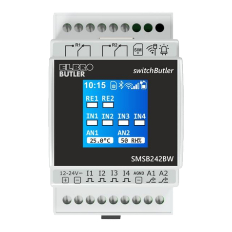
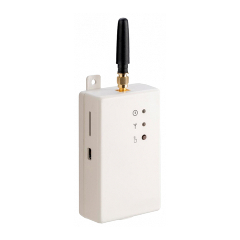
ELBRO SMSB482-V3 User manual

V102 20/10/2020
User's manual
SMSB242/
SMSB482
SMS Switch Butler

2
Table of contents
Qualified personnel............................................................................................................................................................................................4
Liability Disclaimer...........................................................................................................................................................................................4
Comments........................................................................................................................................................................................................5
Safety instructions .............................................................................................................................................................................................6
Installation..........................................................................................................................................................................................................6
Environmental conditions................................................................................................................................................................................6
Protection class ...............................................................................................................................................................................................6
Supply .............................................................................................................................................................................................................6
Digital and analogue inputs ............................................................................................................................................................................6
Relay outputs ..................................................................................................................................................................................................6
Dimensions .........................................................................................................................................................................................................8
Interfaces............................................................................................................................................................................................................8
Wiring diagram..................................................................................................................................................................................................9
Infeed, relay outputs and digital inputs ...........................................................................................................................................................9
Analogue inputs...............................................................................................................................................................................................9
GSM antenna connection...............................................................................................................................................................................10
Digital alarm input connection......................................................................................................................................................................10
Relay output connection.................................................................................................................................................................................10
What is the SMSB242/SMSB482?..................................................................................................................................................................10
SMSB242/SMSB482 interface.........................................................................................................................................................................11
Installing the SIM card..................................................................................................................................................................................11
Installation software......................................................................................................................................................................................11
Software description........................................................................................................................................................................................12
System status..................................................................................................................................................................................................12
Synoptic:....................................................................................................................................................................................................12
Date/time: ..................................................................................................................................................................................................12
Switch:.......................................................................................................................................................................................................12
The relays are switched yy pressing the relay-buttons...............................................................................................................................12
System log: ................................................................................................................................................................................................12
SIM settings ...................................................................................................................................................................................................13
PIN Code:..................................................................................................................................................................................................13
GPRS settings:...........................................................................................................................................................................................13
SIM Credit (only for prepaid cards):..........................................................................................................................................................13
Users list........................................................................................................................................................................................................14
System password: ......................................................................................................................................................................................14
In order to ensure the system safety, the device prompts the operator to enter a four-digit password to be able to send SMS commands.
The default password is made up of four zeroes (0000). Please refer to the SMS commands section to get an overview of all available
commands..................................................................................................................................................................................................14
Enabled users:............................................................................................................................................................................................14
This list contains the phone numbers of users (up to eight) authorized to receive alarm messages and SMS notifications.......................14
Digital inputs allow the user to know specific events regarding the system or the equipment to which the device is connected, such as a
possible boiler block or current drop, as well as a valve opening, etc........................................................................................................15
SMSB242/SMSB482 has eight alarm inputs (four for SMSB242), each of which allows sending to specific users an SMS when the
contact is either opened or closed. The text is customizable for each event; the event can also be delayed in order to avoid false alarms
(anti-bounce) and text messages can be sent sequentially..........................................................................................................................15
Contact type:..............................................................................................................................................................................................15
Trigger:......................................................................................................................................................................................................15
Sequenzial alarm:.......................................................................................................................................................................................15
Link: ..........................................................................................................................................................................................................15
Analog Inputs.................................................................................................................................................................................................16
Type of sensor: ..........................................................................................................................................................................................16
Conversion table:.......................................................................................................................................................................................16
Link: ..........................................................................................................................................................................................................16
Log:............................................................................................................................................................................................................16
Relays ............................................................................................................................................................................................................17
The relays can be manually switched by call function or via SMS. When sending an SMS command for switching on or off, the
SMSB242/SMSB482 responds with a (customizable) text message. On this mask the message text for each relay can be individually
configured..................................................................................................................................................................................................17
Response message: ....................................................................................................................................................................................17
Customized commands:.............................................................................................................................................................................17
Call function..................................................................................................................................................................................................18
Notifications ..................................................................................................................................................................................................19

3
Power failure notification: .........................................................................................................................................................................19
Periodic status message: ............................................................................................................................................................................19
SMS commands................................................................................................................................................................................................20
Special commands............................................................................................................................................................................................20
Stop sequential mode.....................................................................................................................................................................................20
Activation without reply.................................................................................................................................................................................20
Preventing the sending of the signal strength................................................................................................................................................20
Software requirements....................................................................................................................................................................................21
Technical data..................................................................................................................................................................................................21
Declaration of conformity...............................................................................................................................................................................21

4
Warning notices
This manual contains notices which you must observe for your personal safety and for the avoidance of property damage. The
notices for your personal safety are emphasized with a warning triangle; warnings of general property damage do not have a
warning triangle. Depending on the hazard level, warning notices are designated as follows in descending in order of severity.
DANGER
means that death or severe bodily injury will occur if the corresponding precautionary measures
are not taken.
WARNING
means that death or severe bodily injury can occur if the corresponding precautionary measures
are not taken.
CAUTION
with a warning triangle means that minor bodily injury can occur if the corresponding precaution-
ary measures are not taken.
CAUTION
without a warning triangle means that property damage can occur if the corresponding precau-
tionary measures are not taken.
ATTENTION
means that an undesired result or status can occur if the corresponding notice is not observed.
If multiple hazard levels are present at the same time, the warning notice with the highest level is always used. If a warning no-
tice against personal injury has a warning triangle, the same warning notice can also include a warning against property dam-
age.
Qualified personnel
The product/system corresponding to this documentation may only be handled by personnel qualified for the respective task in
observance of the documentation corresponding to the respective task, particularly the safety instructions and warning notices
contained therein. Qualified personnel are capable of recognizing risks and avoid potential dangers when working wit these sys-
tems and products due to their training and experience.
Liability Disclaimer
Elbro AG/Elbro Italia s.r.l. reserves the right to modify the product specifications and/or to cease production of products without
advance warning and with no obligation to supply new functionality or new instructions for products already sold. The manufac-
turer cannot be held liable for loss or damage, direct or indirect, which may result from use of the product. The product is not
suitable for use or application on systems/devices for life support, or in applications where possible malfunction of the same
product could cause damage and/or injury or be a source of hazard to the life or physical safety of people, animals and living
beings. In addition, the product cannot be installed in applications where loss or malfunction could be caused by flooding and/or
fire, and should not be installed in military applications. The device must be used within the climatic limits described in the user
and maintenance manual. It is up to the client to verify that the product is actually compatible with the final installation from a
regulatory perspective. The User should note that handling via the remote control is a free choice, for which they are fully and
exclusively responsible. Use of the product is not permitted for other purposes, for example, to activate external devices and/or
put apparatus into service with fraudulent functions or illegal unlawful intent. We accept no liability arising from failed operations
of the device due to potential faults, signal losses, disconnection of GSM/GPRS network operations or due to external causes
such as incorrect installation or poor maintenance. The product has been tested on operating systems such as Windows 7, 8
and 10. Before installing the software, the User should take care to check the data tariff with their mobile service provider. Elbro
will not accept liability under any circumstances for the costs charged by mobile telephone operators in cases of repeated sms
transmissions or repeated GPRS data connections by the device. Elbro AG has taken the utmost care and attention when draft-
ing this manual; however, it is possible that it could contain errors or omissions. Elbro AG reserves the right to modify and/or
vary parts of this manual in respect of errors, or to modify product features without any advance notification.

5
Comments
•All information contained in this document can be changed without prior notification.
•The duplication of this manual is, depending on the respective technology and means used for this purpose, both electroni-
cally and physically, including photocopies or saving, are only permitted to the user for personal use and prohibited in all
other cases without special written authorization.
•The use, copying, modification, dismantling or transfer of the software are only permitted for the purposes expressly author-
ised by this license; otherwise they are prohibited.
•All other brands or products relate to the respective owners.

6
Safety instructions
•The SMSB242/SMSB482 contains the latest generation of GSM quad-band module. The instructions contained in this
manual must be precisely observed for correct installation and proper use.
•Do not install the SMSB242/SMSB482 in the vicinity of pacemakers, hearing aids or medical devices in general. The
SMSB242/SMSB482 can interfere with the correct operation of these devices.
•The SMSB242/SMSB482 may not be installed in aircraft.
•The SMSB242/SMSB482 may not be operated in atmospheres with gas or flammable gases.
•The SMSB242/SMSB482 operates using a wireless signal. No wireless operator can guarantee a connection at all times.
For this reason the SMSB242/SMSB482 cannot be used with emergency call systems.
Installation
For the safety of the user and in order to ensure the fault-free operation of the SMSB242/SMSB482, the device may only be in-
stalled by qualified experts. The specifications listed below must also be observed.
Environmental conditions
The SMSB242/SMSB482 (the device and all connected cables) must be installed in locations which satisfy the following condi-
tions:
•No dust, no moisture, no high temperatures
•No direct solar radiation
•No devices which radiate heat
•No objects which generate a strong electromagnetic field
•No corrosive liquids or chemical substances
•The SMSB242/SMSB482 was designed for operation at temperatures between and 45 °C (standard operating tempera-
ture).
•Sudden changes in temperature and/or humidity must be avoided.
Protection class
The following protection class must be ensured with the installation of theSMSB242/SMSB482:
•IP40: Minimum protection class which must always be ensured
•IP54: Protection class which only has to be ensured for use outdoors
Supply
The following specifications must be observed:
•Do not use any cables with a length greater than 2m
•The external power supply unit must conform to European standard EN60950 (Electrical safety)
•Ensure the correct polarity (+/-)
Digital and analogue inputs
The following specifications must be observed:
•Only zero-potential contacts may be connected. If analogue sensors are connected, they must be suitable for this purpose
and certified.
•Do not use any cables with a length greater than 2m.
•Do not connect analogue inputs to sources of voltage.
•Do not install cables near electromagnetic fields; otherwise use shielded cable.
•Ensure the correct polarity for the analogue inputs.
Relay outputs
•Observe the technical data in the corresponding chapter.
•Do not use any cables with a length greater than 2m.

7
•Use the same voltage level for all relays: With high-voltage circuits, only the phase conductor may be connected via the re-
lay contacts.

8
Dimensions
Interfaces
1. Relay outputs
2. SMA antenna connection (female)
3. Mini-USB B port
4. Micro SD card slot
5. SIM card slot
6. Infeed
7. Digital inputs (common earth)
8. Analogue inputs (common earth)
9. Code switch for analogue inputs
30°
4,59 mm
61,70 mm
45,40 mm
35,42 mm
Mo Tu We Th Fr Sa Su
IN8IN4
GSM
GPRS
IN1 IN2 IN3 IN5 IN6 IN7
RE1 RE2 RE3 RE4
AN1 AN2
SMSB482
I
O
21
76 8
5 4
3
RS232/
RS485
ANALOG
INPUTS
DIGITAL
INPUTS
12÷ 24V
AN1 AN2 RX/
BTX/
A
IN2 IN5
IN1 IN3 IN4 IN6 IN7 IN8
1000mA
SMSB482
ONLY
SMSB482
ONLY
AN2AN1
ON
1 2 3 4 5
ON
1 2 3 4 5
9

9
Wiring diagram
Infeed, relay outputs and digital inputs
Maximum switching capacity per relay:
5A 250V~ ; 2A 30V=
Maximum switching capacity over all relays: 10A
This value may not be exceeded.
Do not connect any different voltages to the relay:
With 250V~ circuit: Only connect the phase conductor: Do not connect phase and neutral conductors at the relay con-
tact. With low-voltage circuit (DC): Only connect the plus pole.
Analogue inputs
SMSB482
1 2 3 4 5 6 7 8 --+
DIGITALINPUTS
12÷24V
1000mA
NC COM NONC COM NO NC COM NO NC COM NO
RELAY1 RELAY 2 RELAY 3 RELAY4
SW1
SW2
SW3
SW4
SW5
SW6
SW7
SW8
LOAD1 LOAD2 LOAD3 LOAD4
For each relay, the output maximum current is 5A.
Total sum must not exceed 10Aat 250V~
AN1AN2B/RX A/TX
ANALOG
INPUTS RS RS232/ 485
85÷265V~
12÷24V
1000mA
-
+
N
EARTH
L
SAMPLE ELECTRICAL CONNECTION
DRYWET
SMSB482
SMSB482
0..10V +24V GND S1 S2
AN AN1/ 2
probe
ANALOG INPUTS
transmitter
0..10V
LOOP S1 S2
AN AN1/ 2
ANALOG INPUTS
transmitter
0..20mA
LOOP
-+
ON
1 2 3 4 5
probe
AN AN1/ 2
ANALOG INPUTS
PT1000
ON
123 45
AN2AN1
ON
1 2 3 4 5
ON
1 2 3 4 5
ON
1 2 3 4 5
AN AN1/ 2
ANALOG INPUTS
PT100
ON
1234 5
probe
probe

10
GSM antenna connection
Connect a GSM antenna (optional) with a gain of 0 dBm to the male SMS connection.
Digital alarm input connection
Connect the digital inputs to contactors, stepping switches and/or electromechanical switches with zero potential contacts (as
shown in the wiring diagram) in observance of local regulations.
Relay output connection
The installation specifications must be strictly observed in consideration of the rated data (see corresponding chapter).
What is the SMSB242/SMSB482?
Elbro AG developed the SMSB242/SMSB482 to meet the widest range of customer requirements. It is an innovative tool for the
remote control of private and industrial applications via the GSM network. This new system enables remote activation of up to
four devices (up to two for SMSB242) and the monitoring of up to eight alarms (up to four for SMSB242) by means of simple
SMS commands. The SMSB482 has four 5A relay outputs and eight zero-potential alarm inputs which you notify the stored ad-
ministrators via SMS about the status of the installation, such as faults within an installation. The SMS text is freely configurable
for each alarm input for both normally open and normally closed contacts. The device is password-protected and can store and
manage up to eight users.
In order to simplify installation and operation of the device, the SMSB242/SMSB482 is equipped with a large, intuitive LCD dis-
play, which shows information about the GSM signal strength, status of the inputs and outputs, date and time, any errors, etc.
The SMSB242/SMSB482 is very versatile: With the two built-in PT100 and PT1000 analogue inputs which are freely configura-
ble to 0-10V, 0-20mA with code switches, it is possible to set up to two thresholds per analogue input, which trigger an SMS
alarm when the values are undercut or exceeded. The measured values are shown directly on the display and via SMS by
means of a status query. They can also be recorded electronically in the integrated Micro SD card (datalogger function).
The SMSB242/SMSB482 operates with subscription or prepaid mini SIM cards from mobile telephone operators, the DIN hous-
ing enables easy installation into the switch cabinet, the operating voltage is 12-24VDC, the configuration can be transmitted via
PC software and mini USB connection. The installation software is saved on the integrated Micro SD card and is thus safe-
guarded against loss and can be used after several years for reprogramming.
Thanks to the built-in backup super capacitors, the stored users can notified of any potential power failures via SMS.

11
SMSB242/SMSB482 interface
Installing the SIM card
The SIM PIN code, automatic telephone answerer and the services made available by
the provider must be deactivated before installing the SIM card. Ensure that there is
credit available on the SIM card and that its functions are assured by calling and sending
an SMS with a standard mobile phone.
The SMSB242/SMSB482 works with subscription or prepaid SIM, telephone or data
cards. Due to the large number of inputs, the available credit on the SIM card can be
used up immediately when sending multiple SMS alarms, whereby the function of the
device is impaired. We recommend using a subscription SIM card, because it uses its
own wireless channel for data transmission and is not subject to any governmental re-
quirements.
If a prepaid SIM card is used, the SMSB242/SMSB482 has a credit query function. We
recommend activating this function in order to always remain informed of the current
available credit.
Installation software
The installation software of the SMSB242/SMSB482 is stored in the Micro SD mass storage.
In order to start the butler in MSD mode and install the software, you must proceed as follows:
1. Switch off the device (disconnect the supply cable and USB connection)
2. Connect the USB connection cable to the PC;
3. After a few seconds the mass storage is automatically recognized and the folder is opened.
4. Click on setup.exe to install the software;
5. After successful installation, disconnect the USB cable and the device can then be switched on again.
SIM:
visibile quando
la sim è inserita
SMS:
indica l'invio o
ricezionde di SMS
ERR:
indica uno stato
di errore
RTC:
indica data e ora
per datalogger
USB:
connettore
mini-usb
BTN:
pulsanti per la
commutazione
manuale dei relè
INx:
stato degli ingressi
pieno: in allarme
vuoto: cessato allarme
REx:
stato dei relè
com-no: pieno
com-nc: vuoto
GSM:
indica il livello
del segnale ed
i servizi
gsm e gprs
ANx:
ingressi analogici
con unità di misura
MSD:
indica scrittura
su micro SD
MoTuWe ThFrSa Su
IN8IN4
GSM
GPRS
IN1 IN2 IN3 IN5 IN6 IN7
RE1 RE2 RE3 RE4
AN1 AN2
SMSB482
MoTuWe ThFrSa Su
IN8IN4
GSM
GPRS
IN1 IN2 IN3 IN5 IN6 IN7
RE1 RE2 RE3 RE4
AN1 AN2
SIM

12
Software description
System status
Figure 1: System status
Synoptic:
This panel displays the SMSB242/SMSB482 system status on the PC. Every device information is gathered here, such as the
input status, output status, GSM signal level, etc..
Date/time:
The system date can be updated in this screen; the system date is synchronized with the operating system (Windows).
Date and time are only used for the datalogger function.
Switch:
The relays are switched yy pressing the relay-buttons.
System log:
In the LOG table all status messages of the Butler are saved such as receiving/sending SMS or change the status of the inputs.
The LOG table is reset in case of restarting the software.

13
SIM settings
PIN Code:
In this window all SIM settings including the PIN code, definition of the APN settings for GPRS connection and credit interroga-
tion method are defined.
GPRS settings:
The GPRS function allows sending emails from the SMSB242/SMSB482-V2 via a free service provided by the Elbro. This ser-
vice forwards the emails from the Butler to pre-defined e-mail users. However Elbro cannot guarantee the delivery of e-mails
and is not responsible in case of disruptions. Elbro reserves the right cancel this free service to unilaterally at any time and with-
out notice.
WARNING: The use of GPRS data transfer can lead to high telephone costs. Therefore it is advisable to verify with your tele-
phone service provider your subscription. Elbro or its suppliers / partners are not responsible for the loss of revenue, data or
profits, consequential or incidental damages caused (including negligence) arising out of / or in connection with "the use or the
inability to use the product”. The user has been advised by Elbro of the possibility of such damages.
Neither Elbro AG, nor affiliates, wholesalers and retailers can guarantee that the functions of SMSB242/SMSB482-V2 meet the
expectations and that its firmware and software are error-free.
SIM Credit (only for prepaid cards):
it is a very innovative feature for prepaid SIM cards, it allows communicating to the remote user the credit balance of the SIM
card to which the device is connected. Since every phone carrier has a different method to query the credit, this feature can be
configured in the three typical modes foreseen by current phone operators:
•Quick command –for querying the credit.
•Call –for querying the credit.
•Free SMS –for querying the credit.
Please consult your phone carrier for the specific credit query parameters.
This feature is not 100% guaranteed as every phone carrier has a different method to check the credit balance; in addition, they
are always evolving.

14
Users list
Figure 2: List of users
System password:
In order to ensure the system safety, the device prompts the operator to enter a four-digit password to be able to send SMS
commands. The default password is made up of four zeroes (0000). Please refer to the SMS commands section to get an
overview of all available commands.
Enabled users:
This list contains the phone numbers of users (up to eight) authorized to receive alarm messages and SMS notifications.

15
Digital inputs
Figure 3: Digital inputs
Digital inputs allow the user to know specific events regarding the system or the equipment to which the device is connected,
such as a possible boiler block or current drop, as well as a valve opening, etc.
SMSB242/SMSB482 has eight alarm inputs (four for SMSB242), each of which allows sending to specific users an SMS when
the contact is either opened or closed. The text is customizable for each event; the event can also be delayed in order to avoid
false alarms (anti-bounce) and text messages can be sent sequentially.
Contact type:
The following contact types can be set up:
• Dry contact (potential-free dry contact) - in order to trigger an alarm when a potential-free contact is closed.
• Wet contact - in order to trigger an alarm when a voltage between 3V and 24V is connected..
Trigger:
If circuit is closed (with grounding) triggers the alarm.
Sequenzial alarm:
The sequential mode is useful for plant supervisors that have several operators who can work in case of failure.
It allows sending sequentially the digital input alarming messages observing the order found on the list of users with a time in-
terval (default 5 minutes) that can be configured on the system clock screen. The message will however be different compared
to the customized standard, since the user must accept and lock the sequence by sending the command "QUIT" to the device
before working. At this point the SMSB242/SMSB482 will send an SMS message exclusively to those users that were previous-
ly noticed, indicating the user that has accepted and therefore blocked the sequence. If no user blocks the sequence, the
SMSB242/SMSB482 will repeat the entire operation.
In case there is another alarm following the device will automatically block the sequence and will send a message (custom) ex-
clusively to those users that had been previously notified.
Link:
This feature switches a relay output when an event occurs on an associated digital input. The device has four relay outputs,
which can be connected to the digital inputs 1, 2, 3 and 4.
Note: A switching process takes place only after a change of an input status at the related digital input..

16
Analog Inputs
Figure 4: Analogue inputs
The SMSB242/SMSB482 has two analogue alarm inputs that can be configured in 0-10V, 0-20mA, PT100 and PT1000 with
which text messages can be sent to a maximum of eight users when a threshold is exceeded. Two different thresholds can be
set for each input. Refer to the installation diagram to correctly set the dip-switch considering the chosen sensor.
Type of sensor:
Selection of the type of the sensor/probe (for example PT100 or PT1000).
Conversion table:
In this table all desired values can be adjusted.
Link:
This feature allows the connection of one of the four relays to one of the digital inputs.
N.B. La commutazione avviene solamente durante un cambiamento di stato dell’ingresso (fronte evento).
Log:
If enabled, it collects the values of the analogue sensors in the micro-SD card in a CSV file. The sampling time can be set.

17
Relays
Figure 5: Relays
The relays can be manually switched by call function or via SMS.
When sending an SMS command for switching on or off, the SMSB242/SMSB482 responds with a (customizable)
text message. On this mask the message text for each relay can be individually configured.
Response message:
The relay can only be controlled by SMS commands. If you send a command to switch on or off the SMSB242/SMSB482 replies
with an SMS message.
Customized commands:
SMS messages can be programmed individually for each of the four relays in the software mask.

18
Call function
Figure 6: Call function
The device is able to store a list of phone numbers with their relevant names (max 300) that are authorized to activate and/or
deactivate the relay output 1 with a simple phone ring at no cost. The device detects the incoming call and immediately hangs
up, activating at the same time the system it is connected to.
This function can be set through the following modes:
•Exchange: simple relay exchange is done (ON/OFF)
•Pulse: a programmable pulse of 1 up to 65535 seconds (ca. 18 hours) is performed
The user can also activate the SMS feedback option (replying SMS) allowing the reception of an SMS confirming the system
status on the mobile phone from which the phone ring was made.
The PULSE mode also allows customizing the SMS that confirms the command execution.

19
Notifications
Figure 7: Notification SMS
Power failure notification:
This feature allows selected users to receive a notification message when there is a power failure (power drop) and/or when
power is restored. To perform this function, the device is equipped with two super-capacitors; they require at least 30 minutes
charging before any SMS can be sent. The charge status can be viewed as a percentage in the 'System Status' screen.
Periodic status message:
This function periodically sends a system status SMS to the enabled users (daily, weekly or monthly). This mode is useful to
keep a system monitored or to avoid SIM Card’s expiration.

20
SMS commands
The SMSB242/SMSB482 can be configured and controlled through a command set that can be sent by sms. The command
message is password protected (see chapter system password). The following is the command message format:
[PASSWORD]#[COMMAND] for example: 0000#R1#1 (relay n.1 switch-on)
The password is always 4 character long plus #; the hash tag is a mandatory separator.
Commands can be linked and include spaces. ex. 0000#R1#1 R2#1 -> turns relays 1 and 2 on
The following table includes a list of SMS commands with their relevant description and example:
Command
Description
Example
[PW]#R[1-4]#0
deactivates relay outputs from 1 to 4
0000#R1#0
[PW]#R[1-4]#1
activates relay outputs from 1 to 4
0000#R1#1
[PW]#?
query on current status
0000#?
[PW]R[1-4]#T#[1-255]
generates a pulse from 1 to 255 seconds of the se-
lected relay
0000#R1#T#5
Special commands
Stop sequential mode
Send the QUIT[1-8] command when requested by the device through alarm SMS.
Ex. QUIT1
Activation without reply
To stop receiving the replying message from the device, add the following code: -NR (meaning: no reply)
Ex. pulse without reply: 0000#R1#T#5-NR (activates relay 1 for 5 seconds and does not send any confirmation)
Preventing the sending of the signal strength
To prevent the butler from printing the signal strength for outgoing messages, the code {-S} must be added at the end of each
text field. This function is used especially for the communication between remote switchgears of the company ELBRO AG, in
combination with remote switchgears of third-party suppliers.
This manual suits for next models
3
Table of contents
Other ELBRO Switch manuals
