ELBRO switchButler SMSB242BW User manual

switchButler
SMSB242BW
Instruction manual English V1.0
ELBRO BUTLER - full control from everywhere and at all times!
▪Remote switching: Switching devices on or off throughout the world
▪Remote control: Monitoring of devices and systems
▪Alerting: Alerting different persons simultaneously via SMS or email
▪Remote access: 24/7 access to the switching state, temperature and air humidity via SMS
▪Activation: Very easy, thanks to the intuitive app for Android and iOS

2
1Table of contents
2Warning notice concept.................................................................................................................................................................................................................... 3
3Qualified personnel............................................................................................................................................................................................................................ 3
4Disclaimer ............................................................................................................................................................................................................................................ 3
5Email service (COMING SOON) ...................................................................................................................................................................................................... 3
6Notes..................................................................................................................................................................................................................................................... 3
7Warranty.............................................................................................................................................................................................................................................. 3
8Returns................................................................................................................................................................................................................................................. 4
9Installation............................................................................................................................................................................................................................................ 4
9.1 Safety instructions .................................................................................................................................................................................................................................. 4
9.2 Ambient conditions................................................................................................................................................................................................................................. 4
9.3 Supply......................................................................................................................................................................................................................................................... 5
9.4 Digital and analog inputs......................................................................................................................................................................................................................5
9.5 Relay output.............................................................................................................................................................................................................................................. 5
10 SIM card........................................................................................................................................................................................................................................... 5
10.1 Activation.............................................................................................................................................................................................................................................. 5
10.1.1 Inserting the SIM card..................................................................................................................................................................................................................5
11 Scope of supply ............................................................................................................................................................................................................................. 6
12 Product images.............................................................................................................................................................................................................................. 6
13 Application examples ................................................................................................................................................................................................................... 6
14 Accessories..................................................................................................................................................................................................................................... 7
15 Dimensions ..................................................................................................................................................................................................................................... 8
16 Interfaces......................................................................................................................................................................................................................................... 9
17 Installation diagram....................................................................................................................................................................................................................... 10
17.1 Analog inputs ......................................................................................................................................................................................................................................11
17.2 Digital inputs........................................................................................................................................................................................................................................11
17.3 Relays ....................................................................................................................................................................................................................................................11
18 Programming.................................................................................................................................................................................................................................. 11
18.1 Getting started.................................................................................................................................................................................................................................... 11
18.2 Registration..........................................................................................................................................................................................................................................12
18.3 Settings .................................................................................................................................................................................................................................................12
18.4 Coupling the device via Bluetooth ................................................................................................................................................................................................12
18.5 System status......................................................................................................................................................................................................................................13
18.5.1 I/O- status........................................................................................................................................................................................................................................13
18.5.2 LTE module status ........................................................................................................................................................................................................................13
18.6 System settings ..................................................................................................................................................................................................................................13
18.6.1 Interface options............................................................................................................................................................................................................................13
18.6.2 User list............................................................................................................................................................................................................................................. 14
18.7 Alarms and functions........................................................................................................................................................................................................................ 15
18.7.1 Relay..................................................................................................................................................................................................................................................15
18.7.2 Digital and analog inputs............................................................................................................................................................................................................15
18.7.3 Power failure message................................................................................................................................................................................................................15
18.8 Periodic status message..................................................................................................................................................................................................................16
18.9 Wi-Fi settings...................................................................................................................................................................................................................................... 16
18.10 Wireless accessories......................................................................................................................................................................................................................... 17
18.11 Save........................................................................................................................................................................................................................................................17
18.12 System...................................................................................................................................................................................................................................................18
18.12.1 System information..................................................................................................................................................................................................................18
18.12.2 System update..........................................................................................................................................................................................................................18
19 SMS commands............................................................................................................................................................................................................................. 19
19.1 Relay.......................................................................................................................................................................................................................................................19
19.2 Status query.........................................................................................................................................................................................................................................20
19.3 Digital inputs........................................................................................................................................................................................................................................20
19.4 Analog inputs ......................................................................................................................................................................................................................................21
19.5 Voltage supply ....................................................................................................................................................................................................................................21
19.6 User input (COMING SOON).......................................................................................................................................................................................................... 22
19.6.1 Authorisations................................................................................................................................................................................................................................22
19.7 Reset to factory settings..................................................................................................................................................................................................................22
19.8 Automatic function ............................................................................................................................................................................................................................ 23
19.9 Call function .........................................................................................................................................................................................................................................24
20 Manual operation........................................................................................................................................................................................................................... 25
21 Technical data ................................................................................................................................................................................................................................ 25
21.1 Revision history................................................................................................................................................................................................................................... 27

3
2Warning notice concept
This manual contains instructions which you must observe for the purpose of your personal safety as well as for the prevention of material damage.
Instructions with regard to your personal safety are indicated by a hazard triangle, instructions exclusively concerning material damage are shown
without a hazard triangle. Depending on the hazard level, the warning information is represented in descending order as follows.
DANGER
Means that non-compliance with the corresponding precautionary measures may result in death or severe physical
injury.
WARNING
Means that non-compliance with the corresponding precautionary measures may result in death or severe physical
injury.
If several hazard levels apply, the warning notice for the highest level is always used. If the information in a warning notice with the hazard triangle
warns against personal injuries, the same warning notice may include an additional warning against material damage.
3Qualified personnel
The product/system which this documentation applies to must only be handled by personnel qualified for the respective task who take the corre-
sponding documentation for the task in question into account, in particular the safety and warning instructions included. On the basis of their profes-
sional training and experience, qualified personnel must be capable of detecting risks when handling these products/systems and of avoiding poten-
tial hazards.
4Disclaimer
ELBRO AG reserves the right to alter the technical data of the products and/or discontinue their production and provide or remove new functions or
new instructions for products already sold without the need for any prior notification and without any obligation. ELBRO AG can neither be held re-
sponsible for losses nor for direct or indirect damage resulting from the use of the products. The product is not suitable for the use of or in applica-
tions related to parts of life support devices/systems or in applications which, if the product is not working properly, may cause material damage
and/or physical injuries or may pose a danger to life or impair the physical integrity of persons, animals and living beings. Furthermore, the product
must not be used in military applications or for applications in which incorrect functioning or malfunction may cause flooding and/or fires. The device
may only be operated under the climatic conditions specified in the instruction manual and maintenance book.
It is the responsibility of the customer to ensure that the product is compatible with the guidelines for its final installation. The user is aware of the fact
that they shall bear the full and sole responsibility for the optional remote control operation. The product is not suitable for use for other purposes
such as the activation of external devices and/or devices with fraudulent functions or that are used for unlawful purposes.
ELBRO AG assumes no liability for the incorrect functioning of the device due to potential faults, missing signals, interruption of the
LTE/UMTS/GSM/GPRS network or external reasons such as improper installation or maintenance. ELBRO AG shall on no account be liable for the
costs additionally charged by the mobile network operator for the repeated transmission of SMS or repeated GPRS data connection by the device.
Despite diligent preparation of this manual by ELBRO AG, errors or omissions cannot be entirely ruled out. ELBRO AG reserves the right to alter sec-
tions of this manual in the event of errors or changes to the product characteristics without giving any further notice.
5Email service (COMING SOON)
ELBRO AG neither guarantees the successful dispatch of emails nor interruption-free operation of the email service. ELBRO AG reserves the right to
discontinue the service without prior notification. The use of LTE/GPRS/UMTS data can result in high connection costs. We therefore recommend
contacting your telephone provider to find the best subscription option. ELBRO AG and its suppliers will in no event assume liability for lost sales or
lost profits, or for indirect consequential or incidental damage, whether for reasons (including negligence) arising from or in connection with the use or
the impossibility of use of the product, even if the possibility of such damage has been pointed out to ELBRO AG. ELBRO AG, its subsidiaries, affili-
ated companies or group companies, and the distributors and resellers of ELBRO AG do not guarantee that the device will reliably function in accord-
ance with your expectations and that the corresponding firmware and software are free from defects and will work continuously.
6Notes
All information included in this document can be changed without prior notification.. Users may duplicate this manual for personal purposes only,
irrespective of the technique used in each case and the means employed for this purpose both electronically and materially, including photocopies or
storage; duplication is prohibited in all other cases without express written approval. The utilisation, copying, modification, disassembly or transmis-
sion of the software are only permitted for the purposes expressly approved by this license and are otherwise prohibited. All other brands or products
cited are the property of the owner in question.
7Warranty
All ELBRO products are subject to a strict quality control. If an ELBRO Butler should nevertheless not work perfectly,we can only apologise and kindly
ask you to contact your dealer.

4
•The warranty is two years starting from the purchase date. During this period, the warranty will be limited to defects that can be verifiably
traced back to material, execution or design flaws on the part of ELBRO AG.
•The warranty will be exclusively limited to the products delivered by ELBRO. There is no further warranty or entitlement to payment of compen-
sation.. In particular, costs relating to transport, disassembly, assembly and costs due to consequential losses shall not be borne.
•In the case of non-authorised changes or repairs, or if the assembly or operating instructions have not been complied with, the warranty claim
shall be void.
•A warranty service requires that the defective product is delivered in packaged condition, with carriage paid to ELBRO AG.
8Returns
For commercial returns, the requirements defined in our terms of business (AGB) shall apply. Please consult our website to view our detailed return
policy. Repairs to the device must only be performed by ELBRO. Return defective devices to your dealer. Returns for repair by ELBRO will only be
taken into consideration if a comprehensive report on the fault and a receipt proving the purchase of the device within the warranty period are pro-
vided to us. We reserve the right to return devices without a comprehensive report and proof of purchase without comment and to invoice the cost of
the return consignment. Package the device for a return shipment, if possible using the original packaging, so that it can be transported safely.
9Installation
For reasons of safety for the user and to ensure flawless operation of the SMSB242BW, the device must only be installed by qualified personnel.
Furthermore, the provisions listed in the following must be complied with.
9.1 Safety instructions
•The SMSB242BW is provided with a low-power radio transceiver. During operation, it transmits and receives high-frequency energy. Operation
near radios, TVs, telephones or electronic devices in general can cause faults. The SMSB242BW can also be exposed interference factors that
impair its performance.
•Do not install the SMSB242BW near cardiac pacemakers, hearing aids or medical devices in general, since this may affect the proper operation
of these devices.
•The SMSB242BW must not be installed on board of aeroplanes.
•Do not install the SMSB242BW in places where flammable gases or vapours may occur.
•The SMSB242BW works with a radio signal; no mobile operator can guarantee 100% availability of a connection. Therefore, the SMSB131BW
must not be used in life support systems.
9.2 Ambient conditions
The SMSB242BW (the device and all cables connected to it) is to be installed in sites that meet the following conditions:
•No dust, no humidity, no high temperatures
•No direct sunlight
•No devices emitting heat
•No objects that generate a strong electromagnetic field
•No corrosive liquids or chemical substances
•The SMSB242BW has been designed for operation at an ambient temperature between of - 10C and + 70C (operating temperature without
load).
•Sudden temperature and/or humidity changes are to be avoided.
5
9.3 Supply
The following provisions must be complied with:
•Do not use any cables with a length of more than 2.9 m
•The external power supply unit must be a switching power supply certified in compliance with class 2 (LPS).
•Observe the correct polarity of the power supply cables
9.4 Digital and analog inputs
The following provisions must be complied with:
•Only potential-free contacts may be used. If analog sensors are connected, they have to be suitable and certified for this purpose.
•Do not use any cables with a length of more than 2.9 m
•Do not connect analog inputs to voltage sources
•Do not install cables near electromagnetic fields, otherwise use shielded cables
•Observe the correct polarity for analog inputs
9.5 Relay output
•Comply with the technical data in the corresponding chapter
•Do not use any cables with a length of more than 2.9 m
•Use the same voltage level for all relays: In the case of high voltage switching circuits, only the phase conductor may be switched via the
relay contact.
10 SIM card
10.1 Activation
First obtain a Nano SIM card (4FF) from any network provider. The user must activate the
caller ID of the SIM card. It is absolutely essential that you deactivate the PIN code of the SIM
card in advance. If necessary, please contact your network provider for assistance. Keep the
SIM card number and the password secret. Only share this information with the authorised us-
ers, in order to ensure security. We also recommend deactivating the answering machine and
all additional features such as advertising SMS by the telephone operator. Furthermore, make
sure that your SIM card is always provided with sufficient credit and check the correct activa-
tion by sending SMS test messages.
The SMSB242BW works with commercially available SIM cards allowing for the transmission
and reception of SMS. If data only SIM cards are used, the Butler cannot be utilised to its full
extent. In case of doubt, please contact your network provider. If you decide on using a prepaid
SIM card, the SMSB242BW is provided with a credit query. We recommend activating this
features, so as to ensure that you are always in control of your remaining credit.
Does not work with the following SIM cards:
•Data SIM
•Multi SIM
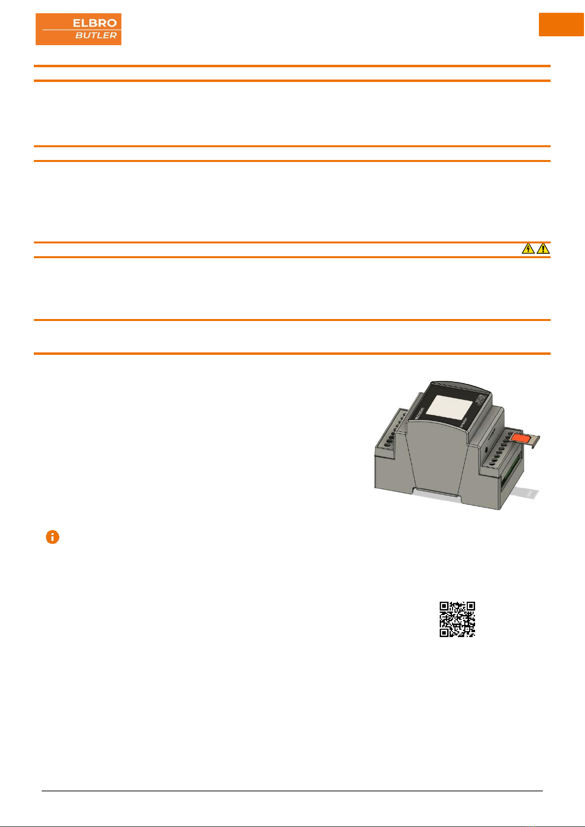
10.1.1 Inserting the SIM card
Please use the ejector pin to remove the tray holder from the SIM slot. The tray holder is es-
sential for inserting the SIM card. Place the SIM card in the tray holder and re-insert it into the
slot. Please note that the SIM card can only be inserted in one direction as shown in the illus-
tration.
Video tutorial:

6
11 Scope of supply
12 Product images
13 Application examples
ELBRO No.
SMSB242BW
E-No.
539 110 260
EAN No.
7611664192753
Description
switchButler Wi-Fi & Bluetooth 2/4/2 channels, GSM/UMTS/LTE.
Scope of supply
•SMSB242BW remote control unit
•Ejector pin
•Tray holder for nano SIM card (4FF)
•Quick guide
•Antenna (integrated)
7
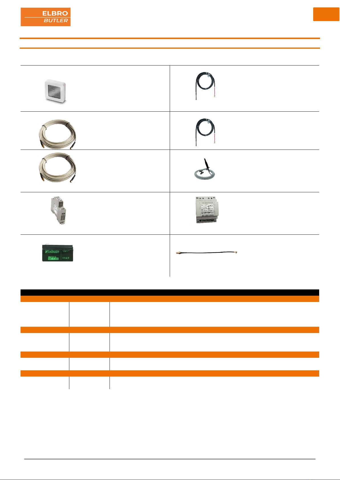
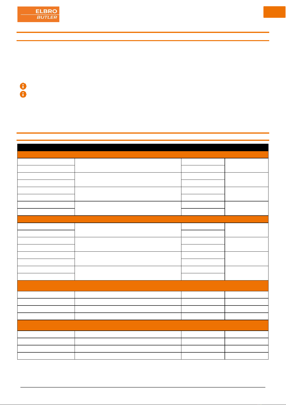
14 Accessories
BTH1
E-No. 536 100 500
SMSB-PT100
E-No. 539 199 010
SMSBV5-01
E-No. 539 190 050
SMSB-PT1000
E-No. 539 199 020
SMSBV10-01
E-No. 539 190 100
SMSBAI-3MLTE
E-No. 539 191 040
SMSBNE12-01
E-No. 960 900 339
SMSBNL121
E-No. 960 900 139
SMSBA1,3E
E-No. 954 876 156
SMSBAI-020M
E-No. 539 191 060
ELBRO No.
E-No.
Description
Power supply units & batteries
SMSBNE12-01
960 900 339
Power supply unit DIN rail mounting 230 VAC /12 VDC / 1 A
SMSBNL121
960 900 139
Power supply unit DIN rail mounting 230 VAC /12 VDC / 1 A connection for battery charging
SMSBA1,3E
SMSBA1,3E
954 876 156
Maintenance-free lead-acid battery 1.3 Ah for use with SMSBNL121
Sensors
BTH1
536 100 500
Bluetooth temperature and humidity sensor
SMSB-PT100
539 199 010
Temperature sensor PT100, PVC cable, 1.5 m, grey
SMSB-PT1000
539 199 020
Temperature sensor PT1000, PVC cable, 1.5 m, grey
Extensions
SMSBV5-01
539 190 050
SMA antenna extension with 5 m cable M/F
SMSBV10-01
539 190 100
SMA antenna extension with 10 m cable M/F
Antennas
SMSBAI-3M-LTE
539 191 040
Multiband antenna with wall mounting bracket, 3 m cable SMA-M plug LTE, GSM, UMTS
SMSBAI-020M
539 191 060
Cable adapter MMCX-SMA 0.2 m, black
8
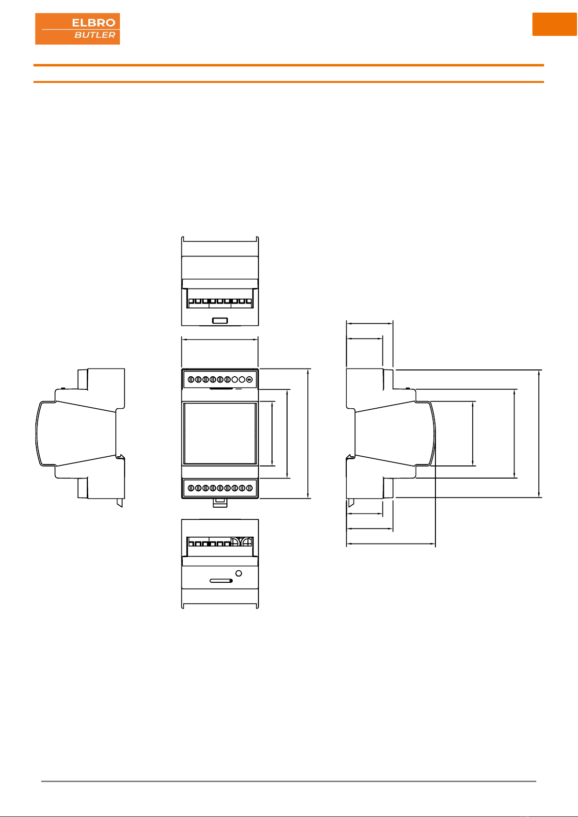
15 Dimensions

9
16 Interfaces
1. Screen
Symbols
Meaning
Only appears when it is con-
nected to another device. Disa-
bled for other devices.
SIM card status
1. Ok
2. SIM-card error
3. SIM-card missing
4. Enter SIM-PIN
5. Enter SIM-puck
WLAN connection
Outgoing messages
4G
Indicates the signal strength and
technology.
Indicates the battery charging
level and whether or not the bat-
tery is connected to the voltage
supply.
LED green - voltage supply o.k.
2. Clamps
Symbol
Contact
LED
Status
R1
Relay 1
On (COM-NC)
Off (COM-NO)
R2
Relay 2
On (COM-NC
Off (COM-NO)
+-
Voltage supply
Digital input 1
Alarm off
Alarm on
Digital input 2
Alarm off
Alarm on
Digital input 3
Alarm off
Alarm on
Digital input 4
Alarm off
Alarm on
AN1
Analog input 1
Real value after application
AN2
Analog input 1
Real value after application
3. Interfaces
1)
SIM
SIM slot for nano SIM card (4FF) with tray holder, insertion as
specified in chapter 10.1.2
2) MMCX antenna connection for extending the antenna using an
SMSBAI-020M adapter
4. Clamps
15 x 12 to 24 (AWG) 0.2 to 3.3 mm²

10
17 Installation diagram
Zero-potential, mechanical contact, e.g. pressure switch, temperature
switch, limit switch, push button, relay output
Voltage output contact, e.g. PLC.

11
17.1 Analog inputs
The SMSB242BW is provided with two analog inputs that can be adjusted to 0-10V, 0-20mA, PT100 and PT1000 and that allow for the transmis-
sion of text messages to several users if threshold values being exceeded or not reached. For each input, two different threshold values can be de-
fined.
17.2 Digital inputs
The digital inputs serve to monitor systems and devices. Via a potential-free contact in the periphery, which can be programmed as NO contact, NC
contact or as voltage dependent contact, the users stored can be alerted via SMS or email.
Wire the inputs as shown in the installation diagram.
17.3 Relays
The relays can be switched manually, via call function, via automatic function and via SMS. If you send an SMS command for switching on or switch-
ing off, the SMSB242BW responds with a message which can be configured individually.
The installation instructions must be strictly observed with regard to the nameplate data (see corresponding chapter).
18 Programming
18.1 Getting started
In general, the SMSB242BW is ready for operation without having to be programmed. Basic commands such as switching on and off can also be
carried out without prior programming. However, if you wish to program these functions, please download the app for your Android or iOS
smartphone. Please connect your SMSB242BW to the power supply unit/the power supply as specified in the instructions.
iOS devices require at least an iPhone 7 for programming!
0..10V
0..1 0V +2 4V G N D S1 S2
probe
transmitter
AN1
1 2 3 4 5
ONON
0..20mA
LO O P S1 S2
transmitter
LO O P
-+
probe
AN1
S1 S2
probe
1 2 3 4 5
ONON
AN1
probe
Pt100
1 2 3 4 5
ONON
Pt1000
AN1
probe
1 2 3 4 5
ONON
5

12
18.2 Registration
You need register once only using the app.
18.3 Settings
In the settings you can select the language for the app; you can also delete your ac-
count here.
18.4 Coupling the device via Bluetooth
After you have registered and logged in successfully, you can view the devices avail-
able via Bluetooth in your proximity. To make the SMSB242BW visible and allow for
successful coupling, it has to be connected to the power supply as specified in the in-
structions. Please select the device to which you wish to couple. The RSSI value
stands for “Received Signal Strength Indicator” (indicator for the received signal
strength) - the lower the value, the better the connection.
To view the demo version, click on the top orange bar 10x

13
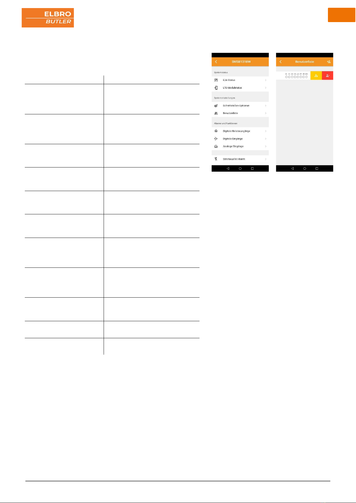
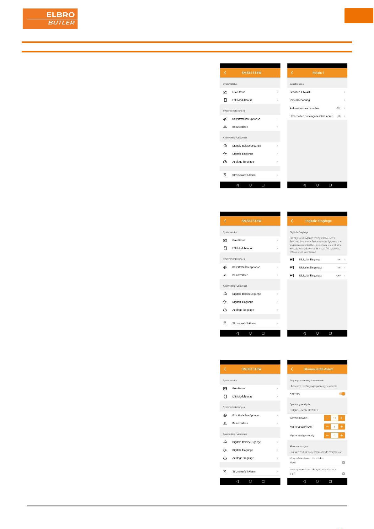
18.5 System status
18.5.1 I/O- status
Overall display of the status of the inputs and outputs of the SMSB242BW.
18.5.2 LTE module status
Details regarding the network of the mobile provider and the telephone status. Here,
important information such as the signal strength, provider, remaining credit and the
technology used is displayed.
18.6 System settings
18.6.1 Interface options
Here you can select relevant safety and comfort settings. Name your device individu-
ally and define an alphanumerical password for incoming text messages.
If you use a prepaid SIM, you can activate the credit query function to continuously
monitor your current costs.
Query code prepaid credit
Swisscom
*130#
Sunrise
*121#
Yallo
*123#
Salt
Service is not supported
14
18.6.2 User list
This list contains the personal data of the users that are authorised to receive alarm
messages. Every user’s profile can be created individually and changed or deleted at
any time. Registered users are enabled to send SMS commands without a password.
In order to edit or delete an existing profile, just swipe to the right.
Functions
Notification/connection
Relay 1
•In/off
•Pulse switching
•Automatic function (logic)
•On an incoming call
Relay 2
•In/off
•Pulse switching
•Automatic function (logic)
•On an incoming call
Digital input 1
•Potential-free contact as NO or NC
contact
•Voltage-dependent contact
Digital input 2
•Potential-free contact as NO or NC
contact
•Voltage-dependent contact
Digital input 3
•Potential-free contact as NO or NC
contact
•Voltage-dependent contact
Digital input 4
•Potential-free contact as NO or NC
contact
•Voltage-dependent contact
Analog input 1
•0-10 V
•0-20 mA; 4-20 mA
•PT100
•PT1000
Analog input 2
•0-10 V
•0-20 mA; 4-20 mA
•PT100
•PT1000
Power failure message
•In the event of a power failure of the
voltage supply
•In the case of voltage-related events
Periodic status message
•Notification on the status at regular
time intervals
Wireless sensors
•In the case of a temperature or hu-
midity alarm
15
18.7 Alarms and functions
18.7.1 Relay
Configure your relays here. Here you can choose between on/off, pulse switching,
automatic switching or switching on an incoming call. In order to be able to use these
functions, please activate the relay permission for the desired user. The text for the
reply messages to an authorised user can be adapted individually.
18.7.2 Digital and analog inputs
18.7.2.1 Digital inputs
The digital inputs can be programmed individually and independently of each other.
Select the type of contact and define the alarm text and any delay for an alarm event.
• Potential-free contact as NO or NC contact
• Voltage-dependent contact
18.7.2.2 Analog inputs
The SMSB242BW is provided with two analog inputs that can be configured with
probes 0-10 V, 0-20 mA, 4-20 mA, PT100 or PT1000.
18.7.3 Power failure message
18.7.3.1 Input voltage
This function makes it possible to send a notification to users defined in advance
when a power failure occurs and/or ends. Any potential power failure is offset in the
device by means of a capacitor.
18.7.3.2 Voltage-related event
Additionally, the voltage supply can be monitored. This function is useful in particular
for systems separated from the network such as self-sufficient traffic surveillance
systems. In this way, for example, a 12 V battery supplied by a photovoltaic system
can be monitored.

16
18.8 Periodic status message
You can use this function to have a message sent to activated users at regular inter-
vals (daily, weekly or monthly). This mode is helpful to permanently monitor an instal-
lation or to avoid the expiry of SIM cards when they are not used for a longer time.
18.9 Wi-Fi settings
Activate Wi-Fi and enter the SSID and the password for the network. It is mandatory
to fill in the password field. The Wi-Fi settings are only required for Internet services
like for example a firmware update.

17
18.10 Wireless accessories
Connection of wireless sensors via Bluetooth. Take the device near the telephone (~5
cm) and press the “Add” button at the top right. After successful coupling, you can
personalise the wireless sensors. Define your own temperature and humidity alarm.
The sensor is mandatory for automatic functioning.
18.11 Save
At the end of each change, the changed parameters must be transferred to the de-
vice through the app. To do so, please click on the moving symbol at the top right of
the screen. Confirm the message shown with OK. After the save process has been
completed, the symbol disappears.
18
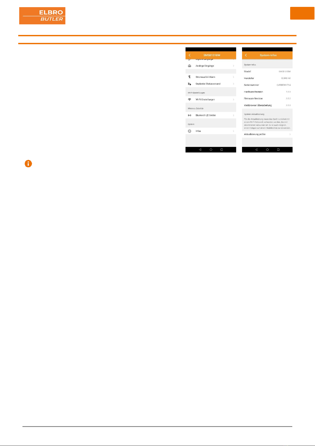
18.12 System
18.12.1 System information
Display of relevant system information.
Model
Manufacturer
Serial number
Hardware revision
Firmware revision
Web browser revision
18.12.2 System update
If new firmware is available, this will be shown when the device is connected. To
carry out the update, the device first must be logged in to a Wi-Fi network that is
connected to the Internet. A mobile phone hotspot can also be used for this purpose .
Then select "Check update" and your device will check automatically whether new
firmware is available.
The system update is also possible manually via the input on the control
panel
19
19 SMS commands
The SMSB242BW is provided with various configuration and control commands that can be sent via SMS. Command messages are protected by a
password.
The format of the command message is as follows:
[PASSWORD]#[COMMAND] Example: 0000#1
The default password for a command message is →0000
Registered users in the user list are enabled to send commands without a password
A password must always have a length of 4 characters plus # hash mark as an obligatory separator. You can replace it by the 'point’ character. To
learn how ton change a password, please refer to chapter 16.6.1.
The following tables show a list of SMS commands with descriptions and examples:
19.1 Relay
Command
Description
Example
Notes
Switch-on
[PASSWORD]#R1#1
Switch on relay 1 (COM-NO)
0000#R1#1
[PASSWORD]#R1#ON
0000#R1#ON
[PASSWORD]#R2#1
Switch on relay 2 (COM-NO)
0000#R2#1
[PASSWORD]#R2#ON
0000#R2# ON
[PASSWORD]#R3#1
Switch on relay 3 (COM-NO)
0000#R3#1
[PASSWORD]#R3#ON
0000#R3# ON
[PASSWORD]#R4#1
Switch on relay 4 (COM-NO)
0000#R4#1
[PASSWORD]#R4#ON
0000#R4#ON
Switch-off
[PASSWORD]#R1#0
Switch off relay 1 (COM-NC)
0000#R1#0
[PASSWORD]#R1#OFF
0000#R1#OFF
[PASSWORD]#R2#0
Switch off relay 2 (COM-NC)
0000#R2#0
[PASSWORD]#R2#OFF
0000#R2#OFF
[PASSWORD]#R3#0
Switch off relay 3 (COM-NC)
0000#R3#0
[PASSWORD]#R3#OFF
0000#R3#OFF
[PASSWORD]#R4#0
Switch off relay 4 (COM-NC)
0000#R4#0
[PASSWORD]#R4#OFF
0000#R4#OFF
Execute pulse function
Saves the pulse value between 1 and 300 seconds.
[PASSWORD]#R1#P#[1-300]
Relay 1 pulse function 5s saved
0000#R1#P#5
[PASSWORD]#R2#P#[1-300]
Relay 2 pulse function 5s saved
0000#R2#P#5
[PASSWORD]#R3#P#[1-300]
Relay 3 pulse function 5s saved
0000#R3#P#5
[PASSWORD]#R4#P#[1-300]
Relay 4 pulse function 5s saved
0000#R4#P#5
Execute pulse function
Switches the relay to pulse operation with the value saved.
[PASSWORD]#R1#P
Pulse function relay 1 execute 5s
0000#R1#P
[PASSWORD]#R2#P
Pulse function relay 2 execute 5s
0000#R2#P
[PASSWORD]#R3#P
Pulse function relay 3 execute 5s
0000#R3#P
[PASSWORD]#R4#P
Pulse function relay 4 execute 5s
0000#R4#P

20
19.2 Status query
Command
Description
Example
Notes
General
[PASSWORD]#?
Query status relay, credit, signal strength, sensors
0000#?
[PASSWORD]#STATUS
0000#STATUS
Relay
[PASSWORD]#R1#?
Query status relay 1
0000#R1#?
[PASSWORD]#R1#STATUS
0000#R1#STATUS
[PASSWORD]#R2#?
Query status relay 2
0000#R2#?
[PASSWORD]#R2#STATUS
0000#R2#STATUS
[PASSWORD]#R3#?
Query status relay 3
0000#R3#?
[PASSWORD]#R3#STATUS
0000#R3#STATUS
[PASSWORD]#R4#?
Query status relay 4
0000#R4#?
[PASSWORD]#R4#STATUS
0000#R4#STATUS
Firmware
[PASSWORD]#VER
Query firmware version
0000#VER
19.3 Digital inputs
Command
Description
Example
Notes
Activation
[PASSWORD]#D1#1
Activate digital input 1
0000#D1#1
[PASSWORD]#D1#ON
0000#D1#ON
[PASSWORD]#D2#1
Activate digital input 2
0000#D2#1
[PASSWORD]#D2#ON
0000#D2#ON
[PASSWORD]#D3#1
Activate digital input 3
0000#D3#1
[PASSWORD]#D3#ON
0000#D3#ON
[PASSWORD]#D4#1
Activate digital input 4
0000#D4#1
[PASSWORD]#D4#ON
0000#D4#ON
Deactivation
[PASSWORD]#D1#0
Deactivate digital input 1
0000#D1#0
[PASSWORD]#D1#OFF
0000#D1#OFF
[PASSWORD]#D2#0
Deactivate digital input 2
0000#D2#0
[PASSWORD]#D2#OFF
0000#D2#OFF
[PASSWORD]#D3#0
Deactivate digital input 3
0000#D3#0
[PASSWORD]#D3#OFF
0000#D3#OFF
[PASSWORD]#D4#0
Deactivate digital input 4
0000#D4#0
[PASSWORD]#D4#OFF
0000#D4#OFF
Status query
[PASSWORD]#D1#?
Query status digital input 1
0000#D1#?
[PASSWORD]#D1#STATUS
0000#D1#STATUS
[PASSWORD]#D2#?
Query status digital input 2
0000#D2#?
[PASSWORD]#D2#STATUS
0000#D2#STATUS
[PASSWORD]#D3#?
Query status digital input 3
0000#D3#?
[PASSWORD]#D3#STATUS
0000#D3#STATUS
[PASSWORD]#D4#?
Query status digital input 4
0000#D4#?
[PASSWORD]#D4#STATUS
0000#D4#STATUS
Table of contents
Other ELBRO Switch manuals


