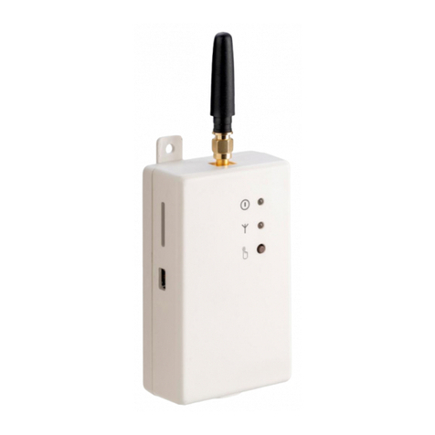
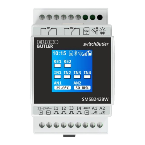
ELBRO SMSB221T User manual

Bedienungsanleitung
User's manual
Manuel de l'utilisateur
Istruzioni per l’uso
SMSB221T
de
en
fr
it
de
en
fr
it
SMS Switch Butler

RELEASE V202_22/01/13

de
en
fr
it
de
en
fr
it
1
SMSB221T - SMS Switch Butler
Inhalt
de
de
Sicherheitshinweise . . . . . . . . . . . . . . . . . . . . . . . . 2
Anmerkungen. . . . . . . . . . . . . . . . . . . . . . . . . . . . . . . . . . . . . . . . . . . . . . . . . 2
Installation . . . . . . . . . . . . . . . . . . . . . . . . . . . . 2
Umgebungsbedingungen . . . . . . . . . . . . . . . . . . . . . . . . . . . . . . . . . . . . . . . . . . . 2
Schutzart . . . . . . . . . . . . . . . . . . . . . . . . . . . . . . . . . . . . . . . . . . . . . . . . . . . 2
Versorgung. . . . . . . . . . . . . . . . . . . . . . . . . . . . . . . . . . . . . . . . . . . . . . . . . . 2
Signaleingänge . . . . . . . . . . . . . . . . . . . . . . . . . . . . . . . . . . . . . . . . . . . . . . . . 2
Relaisausgänge . . . . . . . . . . . . . . . . . . . . . . . . . . . . . . . . . . . . . . . . . . . . . . . . 2
Anschlussschema. . . . . . . . . . . . . . . . . . . . . . . . . . . . . . . . . . . . . . . . . . . . . . . 3
Einsetzen der SIM-Karte . . . . . . . . . . . . . . . . . . . . . . . . . . . . . . . . . . . . . . . . . . . 4
Anschluss der digitalen Alarmeingänge . . . . . . . . . . . . . . . . . . . . . . . . . . . . . . . . . . . . 4
Anschluss des externen Fühlers (im Lieferumfang nicht enthalten) . . . . . . . . . . . . . . . . . . . . . . 4
Anschluss der GSM-Antenne . . . . . . . . . . . . . . . . . . . . . . . . . . . . . . . . . . . . . . . . . 4
Anschluss der Relaisausgänge . . . . . . . . . . . . . . . . . . . . . . . . . . . . . . . . . . . . . . . . 4
Programmierung . . . . . . . . . . . . . . . . . . . . . . . . . 4
Installation der Programmiersoftware. . . . . . . . . . . . . . . . . . . . . . . . . . . . . . . . . . . . . 4
Programmierung über USB-Kabel . . . . . . . . . . . . . . . . . . . . . . . . . . . . . . . . . . . . . . 5
Funktionen . . . . . . . . . . . . . . . . . . . . . . . . . . . . 5
Systempasswort . . . . . . . . . . . . . . . . . . . . . . . . . . . . . . . . . . . . . . . . . . . . . . . 5
Liste der Administrator-Benutzer . . . . . . . . . . . . . . . . . . . . . . . . . . . . . . . . . . . . . . . 5
Temperaturfühler . . . . . . . . . . . . . . . . . . . . . . . . . . . . . . . . . . . . . . . . . . . . . . . 5
Kalibrieren . . . . . . . . . . . . . . . . . . . . . . . . . . . . . . . . . . . . . . . . . . . . . . . . . . 5
Raumthermostatfunktion . . . . . . . . . . . . . . . . . . . . . . . . . . . . . . . . . . . . . . . . . . . 5
Analog-Eingang. . . . . . . . . . . . . . . . . . . . . . . . . . . . . . . . . . . . . . . . . . . . . . . . 5
Alarmeingänge . . . . . . . . . . . . . . . . . . . . . . . . . . . . . . . . . . . . . . . . . . . . . . . . 5
Telefonanruffunktion . . . . . . . . . . . . . . . . . . . . . . . . . . . . . . . . . . . . . . . . . . . . . 5
Guthabenfunktion. . . . . . . . . . . . . . . . . . . . . . . . . . . . . . . . . . . . . . . . . . . . . . . 6
Schnittstellen . . . . . . . . . . . . . . . . . . . . . . . . . . . 6
LED1: Relais-Status des Relais-Ausgangs Nr. 1 und GSM-Signalstärke . . . . . . . . . . . . . . . . . . . . 6
LED2: Relais-Status des Relais-Ausgangs Nr. 2 . . . . . . . . . . . . . . . . . . . . . . . . . . . . . . . . 6
Taste zum manuellen Umschalten. . . . . . . . . . . . . . . . . . . . . . . . . . . . . . . . . . . . . . . 6
SMS-Befehle . . . . . . . . . . . . . . . . . . . . . . . . . . . 7
Fehlerbehebung . . . . . . . . . . . . . . . . . . . . . . . . . 7
Softwareanforderungen . . . . . . . . . . . . . . . . . . . . . . . 8
Kenndaten . . . . . . . . . . . . . . . . . . . . . . . . . . . . 8
CE Konformitätserklärung . . . . . . . . . . . . . . . . . . . . . . 8

2
Sicherheitshinweise
Der SMSB221T enthält ein GSM-Dualband-Modul der letzten Generation. Für den korrekten Einbau und sachgemässe Anwendung
sind die in diesem Handbuch enthaltenen Hinweise genauestens zu beachten.
Beim SMSB221T handelt es sich um einen Low Power Funksender/Empfänger. Wenn das Gerät in Betrieb ist, sendet und empfängt es
Funkfrequenzenergie. Der Betrieb des SMSB221T in der Nähe von Radioapparaten, Fernsehgeräten, Telefonen oder elektronischen
Geräten im Allgemeinen kann Interferenzen hervorrufen. Der SMSB221T kann von Interferenzen betroffen sein, die möglicherweise auf
die Leistungen des Geräts Einfluss nehmen.
Den SMSB221T nicht in der Nähe von Herzschrittmachern, Hörgeräten oder medizinischen Apparaten im Allgemeinen installieren. Der
SMSB221T kann den einwandfreien Betrieb dieser Geräte beeinträchtigen.
An Bord von Flugzeugen muss der SMSB221T ausgeschaltet werden. Sicherstellen, dass das Gerät nicht aus Versehen wieder
eingeschaltet werden kann.
In Atmosphären mit Gas oder brennbaren Gasen darf der SMSB221T nicht verwendet werden. Das Gerät in der Nähe von Tankstellen,
Treibstoffdepots und chemischen Anlagen ausschalten.
Der SMSB221T arbeitet unter Verwendung eines Funksignals. Kein Mobilfunkbetreiber kann die Verbindung jederzeit gewährleisten.
Aus diesen Gründen kann der SMSB221T nicht mit Hausnotrufsystemen eingesetzt werden.
Anmerkungen
Alle in diesem Handbuch enthaltenen Informationen können ohne Vorankündigung geändert werden.
Die Vervielfältigung dieses Handbuchs ist, unabhängig von der jeweiligen Technik und dem dafür eingesetzten Mittel sowohl
elektronisch als auch materiell einschliesslich Fotokopien oder Speicherung nur dem Benutzer zu persönlichen Zwecken gestattet und
ohne besondere schriftliche Genehmigung in allen anderen Fällen verboten.
Verwendung, Kopie, Änderung, auseinander legen oder Übertragung der Software sind nur zu den ausdrücklich mit dieser Lizenz
genehmigten Zwecken gestattet und ansonsten verboten.
Alle anderen genannten Marken oder Produkte beziehen sich auf den jeweiligen Eigentümer.
Installation
Aus Sicherheitsgründen für den Benutzer und um den einwandfreien Betrieb des SMSB221T zu gewährleisten, darf das Gerät
ausschliesslich von Fachpersonal installiert werden. Einzuhalten sind ausserdem die nachfolgend aufgeführten Vorschriften:
Umgebungsbedingungen
Der SMSB221T (das Gerät und alle daran angeschlossenen Kabel) ist an Orten zu installieren, die folgende Bedingungen erfüllen:
Kein Staub, keine Feuchtigkeit, keine hohen Temperaturen
Keine direkte Sonnenbestrahlung
Keine Geräte, die Wärme abgeben
Keine Gegenstände, die ein starkes elektromagnetisches Feld erzeugen
Keine korrosiven Flüssigkeiten oder chemische Substanzen
Der SMSB221T wurde für den Betrieb bei einer Temperatur zwischen - 5 °C und + 45 °C ausgelegt (Standardbetriebstemperatur).
Plötzliche Änderungen von Temperatur und/oder Feuchtigkeitsgehalt sind zu vermeiden.
Schutzart
Bei der Installation des SMSB221T ist die nachfolgende Schutzart zu gewährleisten:
IP40: Mindestschutzart, muss immer gewährleistet sein
IP54: Nur beim Einsatz für Anwendung im Freien zu gewährleistende Schutzart
Versorgung
Folgende Vorschriften sind einzuhalten:
Keine Kabel mit einer Länge über 2m verwenden
Das externe Netzteil (zum Beispiel Steckernetzteil) muss der Europäischen Norm EN 60950 (elektrische Sicherheit) entsprechen.
Auf die korrekte Polarität achten (+/-)
Signaleingänge
Folgende Vorschriften sind einzuhalten:
keine Kabel mit einer Länge über 2m verwenden
keine Kabel in der Nähe von elektromagnetischen Feldern verlegen, ansonsten abgeschirmte Kabel verwenden.
Relaisausgänge
Bei der Installation des SMSB221T sind die im Handbuch enthaltenen Hinweise genauestens zu beachten. Die externen Geräte
sachgemäss installieren und die in diesem Handbuch enthaltenen Kenndaten beachten. Die Werte der Kenndaten dürfen auf keinen
Fall überschritten werden.

de
en
fr
it
de
en
fr
it
3
SMSB221T - SMS Switch Butler
Beschreibung
Anschlussspannung: 12-24VDC - 1000mA
Antenne: GSM SMA Quad-band 850/900 - 1800/1900MHz
USB-Abschluss für die Programmierung am PC
Taste zum manuellen Umschalten der Relaisausgänge
Kontrollleuchte Relais Nr. 1 (ROT - EIN, GRÜN - AUS) und GSM-Signalstärke
Kontrollleuchte Relais Nr. 2 (ROT - EIN, GRÜN - AUS)
Potentialfreie Digital-Eingänge (2 Stk.)
Einstellbarer Analog-Eingang via Dip-Switch (0-5V;0-10V;(0)4-20mA;PT100;PT1000)
Relais-Ausgänge (2 Stk.) 5A - 250V AC, 2A - 30VDC
Nr.
1
2
3
4
5
6
7
8
9
Anschlussschema
de
de
12V-24V DC
SMSB221T
12
C
NC
NO
C
NC
NO
RELAY 2RELAY 1
I1 I2
PROBE

4
Anschluss der digitalen Alarmeingänge
Das Gerät verfügt über zwei Alarm-Eingänge, sowohl beim Schliessen als auch beim Öffnen des Kontakts wird ein SMS-Alarm an bis zu
sechs Administratoren gesendet. Die digitale Eingänge sind (gem. Installationsschema) im spannungslosen Zustand an potentialfreien
Kontakten von Maschinen oder Schaltern anzuschliessen. Dabei sind die örtlichen Vorschriften einzuhalten. Dank dieser Funktion wird der
Benutzer über bestimmte Ereignisse der Systeme oder Anlagen, an die das Gerät angeschlossen ist, informiert. Dabei kann es sich
beispielsweise um eine eventuelle Störung des Heizkessels, einen Spannungsabfall oder das Öffnen eines Ventils usw. handeln.
Anschluss des externen Fühlers (im Lieferumfang nicht enthalten)
Den Fühler bei AUSGESCHALTETEM Gerät anschließen (im Lieferumfang nicht enthalten).
Der externe Fühler ist an den Klemmen des Digital-Eingangs anzuschliessen, wie auf Seite 3 abgebildet.
Anschluss der GSM-Antenne
Die GSM-Antenne an den SMA-Stecker schrauben (siehe Darstellung im Installationsdiagramm).
Anschluss der Relais-Ausgänge
Das Gerät ist mit zwei Relais-Ausgänge ausgestattet, die Belastungen bis maximal 5A (ohmsche Last) schalten können.
Die Installationsvorschriften unter Berücksichtigung der Nenndaten (siehe entsprechendes Kapitel) sind strikte zu beachten.
HINWEIS: Relais-Ausgang Nr. 1 kann per SMS und/oder Anruf aktiviert oder deaktiviert, oder automatisch mit Temperaturfunktionen
angesteuert werden; Relais-Ausgang Nr. 2 kann nur per SMS angesteuert werden.
Programmierung
Installation der Programmiersoftware
Schritte zur Installation der Software:
• Die CD in das CD-ROM-Laufwerk des PC›s einlegen
• den automatischen Start der CD-ROM abwarten. Ist die automatische Startfunktion deaktiviert, das Symbol der CD-ROM unter
Arbeitsplatz mit einem Doppelklick der rechten Maustaste auswählen und AutoPlay anklicken
• das Setup-Symbol „Installieren“ anklicken
Achtung: Während der Softwareinstallation muss ggf. Microsoft.NET Framework 4 installiert werden. Eventuell ist eine
Internetverbindung erforderlich.
Einsetzen der SIM-Karte
Vor dem Einsetzen der SIM-Karte
Die SIM-Karte darf PIN geschützt sein.
Der Anrufbeantworter muss deaktiviert werden.
Zum Einsetzen der SIM-Karte die Frontabdeckung des Geräts abnehmen. Hierzu ein geeignetes Werkzeug in den entsprechenden Schlitz
einführen und eine Hebelwirkung ausüben, sodass die Abdeckung abgenommen werden kann.
Die Klappe nach oben drücken, durch Einrasten entriegeln und dann anheben
die SIM-Karte einlegen. Der Chip muss in Richtung der Kontakte zeigen, die Diagonale muss nach oben rechts gerichtet sein
die Klappe leicht nach unten drücken und schließen
Die Frontabdeckung wieder einsetzen und das Gerät schließen.
Die SIM-Karte darf nur bei AUSGESCHALTETEM Gerät eingesetzt und entfernt werden.
Das Gerät funktioniert sowohl mit SIM-Karten mit aufladbarem Guthaben und mit Abonnement als auch mit Daten-SIM-Karten. Mit
Letztgenannten können jedoch nur SMS gesendet und empfangen werden. Die „Anruffunktion“ steht damit nicht zur Verfügung.

de
en
fr
it
de
en
fr
it
5
SMSB221T - SMS Switch Butler
Programmierung über USB-Kabel
Zur Programmierung muss das Gerät selbst nicht an die Stromversorgung angeschlossen sein, da diese direkt über den USB-Anschluss
erfolgt. Das Gerät kann daher vor dem Einbau im Schaltkasten programmiert werden.
HINWEIS: Die Relais können Ihren Status nur ändern, wenn der SMSB221T an die Hauptstromversorgung angeschlossen ist.
• Die Programmiersoftware starten
• Das Gerät per USB-Kabel mit dem PC verbinden
Das Gerät benötigt keinen Installationstreiber, da es von Windows automatisch erkannt wird. Dies vereinfacht eine zukünftige
Neuprogrammierung des Geräts.
Wird das Gerät nicht erkannt und blinkt die Netz-LED weiter rot, im Kapitel über Fehlerbehebung weiterlesen.
Die Programmiersoftware Butlers ist einfach, leicht verständlich und intuitiv. In den nächsten Kapiteln wird jede Funktion der
Programmiersoftware detailliert erläutert.
Funktionen
Systempasswort
Um die Systemsicherheit zu garantieren, muss ein vierstelliges Passwort (Ziffern und/oder Buchstaben) eingegeben werden. Dies ist für
das senden der SMS-Befehle unbedingt erforderlich. Die Werkseinstellung ist viermal null (0000). Für das senden der SMS-Befehle im
entsprechenden Kapitel weiterlesen.
Liste der Administrator-Benutzer
Diese Liste enthält die Telefonnummern der Benutzer, die zum Empfangen von SMS-Alarmen sowie zur Bedienung des Geräts mithilfe der
Schnellbefehle (siehe entsprechendes Kapitel) berechtigt sind.
Temperaturfühler
Das Gerät verfügt über einen internen Temperaturfühler, der die Temperatur im Schaltkasten misst.
HINWEIS: Die gemessene Innentemperatur ist nur ein Richtwert, da sie von der Gerätetemperatur sowie der Temperatur des
Schaltkastens, in dem das Gerät eingebaut ist, beeinflusst wird.
Kalibrieren
Die Messung jedes Fühlers kann kalibriert werden. Dabei ist zu berücksichtigen, dass die Temperatur des externen Fühlers im Vergleich zu
der des internen Fühlers äußerst präzise ist. Empfohlen wird das Kalibrieren des internen Fühlers am externen Fühler.
Raumthermostatfunktion
Mithilfe dieser Funktion kann der Relais-Ausgang Nr. 1 in Abhängigkeit der von einer der beiden Temperatursonden gemessenen
Tenmperatur geschaltet werden. Beim Anschluss an ein Heizungs- oder Klimagerät wird die Raumtemperatur über die AUTOMATIK-
Funktion angesteuert. Die Temperaturgrenzwerte können sowohl über die Software als auch per SMS-Befehle (siehe Kapitel über die
Befehle) festgelegt werden.
Analog-Eingang
Der SMSB221T ist mit einem Multifunktions-Analog-Eingang ausgerüstet, an welchen Sonden vom Typ 0-10V, 0-5V, (0)4-20mA, PT100
und PT1000 angeschlossen werden können. Für die Einstellung der Sonde muss die richtige Codierung über den unten rechts montierten
DIP-Switch vorgenommen werden, wie folgt:
Alarmeingänge
Das Gerät verfügt über zwei Alarm-Eingänge. Sowohl beim Schliessen wie auch beim Öffnen des Kontakts wird ein SMS-Alarm an bis zu
sechs Administratoren gesendet. Der Text jedes Ereignisses kann sowohl mittels Software als auch per SMS-Befehl benutzerdefiniert
werden. Dank dieser Funktion wird der Benutzer über bestimmte Ereignisse der Systeme oder Anlagen, an die das Gerät angeschlossen
ist, informiert. Dabei kann es sich beispielsweise um eine eventuelle Störung des Heizkessels, einen Spannungsabfall oder das Öffnen
eines Ventils usw. handeln.
Telefonanruffunktion
Das Gerät kann eine Liste von Telefonnummern mit den zugehörigen Namen (maximal 300) speichern, die berechtigt sind, den Relais-
Ausgang Nr. 1 durch einen einfachen kostenlosen Telefonanruf zu aktivieren/deaktivieren. Das Gerät erkennt den eingehenden Anruf,
quittiert ihn nach Kontrolle der Rufnummer unverzüglich und aktiviert gleichzeitig die vorgängig in der Software definierte Funktion. Es ist
wichtig den Anrufbeantworter zu deaktivieren, ansonsten dieser das Gespräch übernimmt und diese Funktion mit Telefonkosten belastet
wird.
de
de
0-10V
(0)4-20mA
0-5V
PT100 PT1000

6
Diese Funktion (RMODE) kann wie folgt eingerichtet werden:
• Funktion deaktiviert
• Wechsel-Modus (Umschalten): das Relais wird umgeschaltet (EIN/AUS), in diesem Modus wird die Thermostatfunktion deaktiviert
• Puls-Modus (Impuls): ausgeführt wird ein Impuls (programmierbar von 1 bis 20 Sekunden), in diesem Modus wird die Thermostatfunktion
deaktiviert
• A utomatik-Modus: Wechseln zwischen vordefinierter Komforttemperatur und Frostschutztemperatur des Raumthermostats (nur wenn die
Thermostatfunktion zuvor aktiviert wurde)
Der Benutzer kann zudem die Option SMS-Bestätigung aktivieren: An das Mobiltelefon, von dem der Anruf einging, wird eine SMS zur Bestätigung
des Anlagenzustands gesendet.
Im Puls-Modus kann der Text der SMS-Bestätigung des gesendeten Befehls zudem benutzerdefiniert werden.
Guthabenfunktion
Mit dieser Funktion für Prepaid SIM-Karten kann der Benutzer über das Restguthaben auf der SIM-Karte, welche im Gerät eingesetzt ist, informiert
werden. Da jeder Telefonanbieter unterschiedliche Methoden zum Abfragen des Guthabens verwendet, kann diese Funktion auf drei verschiedene
Arten eingerichtet werden, die den bei Telefonanbietern gängigen Verfahren entsprechen:
über Schnellbefehl
über das Anrufen einer Nummer, um eine SMS-Nachricht mit Angabe des Guthabens zu empfangen
über den kostenlosen SMS-Vesand mit einem Befehl zum Empfangen des Guthabens
Setzen Sie sich mit Ihrem Telefonanbieter in Verbindung, um zu erfahren, welche Parameter Sie eingeben müssen. Diese Funktion wird nicht
garantiert, denn jeder Telefonanbieter benutzt ein anderes Verfahren, um Informationen über das Restguthaben abfragen zu lassen. Diese werden
außerdem ständig weiterentwickelt.
Schnittstellen
LED1: Relais-Status des Relais-Ausgangs Nr. 1 und GSM-Signalstärke
Im Stand-by-Modus wird die GSM-Signalstärke angezeigt. In der nachfolgenden Tabelle wird die Funktionsweise beschrieben:
LED2: Relais-Status des Relais-Ausgangs Nr. 2
Siehe nächsten Paragraph.
Taste zum manuellen Umschalten
Durch kurzen Betätigen der Taste wird vom Stand-by-Modus zum Anzeige-Modus der Relais-Ausgänge umgeschaltet. Wird die Taste
länger als 2 Sekunden gedrückt, so kann zwischen den Relais-Ausgängen umgeschaltet werden, deren Status wiederum per kurzen
Tastendruck geändert wird (ON - OFF und umgekehrt). Nach 5 Sekunden kehrt die Anzeige in den Stand-by-Modus zurück (Anzeige der
GSM-Signalstärke).
Beschreibung
Das Gerät empfängt kein Signal und/oder ist nicht im Netzwerk registriert
Fehler: Verwiesen wird auf das Kapitel Fehlerbehebung.
Die Zahl der Blinksignale entspricht der GSM-Signalstärke: 1 bis 5.
Das Gerät sendet oder empfängt SMS.
Farbe der LED
DAUERLICHT ROT
BLINKLICHT ROT
BLINKLICHT GRÜN
DAUERLICHT GRÜN

de
en
fr
it
de
en
fr
it
7
SMSB221T - SMS Switch Butler
Fehlerbehebung
Bei Störungen blinkt die Status-LED (LED1) rot. Die gezählten Blinksignale haben folgende Bedeutungen:
Beschreibung
GSM-Signal wird nicht empfangen
Die SIM-Karte ist durch eine PIN-Zahl geschützt
Keine SIM-Karte eingesetzt
Die SIM-Karte funktioniert nicht/defekt
Systemfehler: Das Gerät neu starten
Die SIM-Karte ist durch eine PUK-Zahl geschützt
Blinksignale
1
2
3
4
5
6
de
de
SMS-Befehle
Das Gerät verfügt über eine Reihe von Konfigurations- und Steuerungs-/Schaltbefehlen, die über SMS gesendet werden können.
Der SMS-Befehl ist passwortgeschützt (siehe Systempasswort). SMS-Befehle haben folgendes Format:
[PASSWORT]#[BEFEHL]#[BEFEHL] Beispiel: 0000#R1#1 (Relais Nr. 1 ein)
Wobei Folgendes gilt:
das Passwort ist stets vierstellig
das Rautezeichen (#) ist ein obligatorisches Trennzeichen (alternativ kann auch nur das Punktzeichen verwendet werden).
Nachfolgend ist eine Liste der verfügbaren Standardbefehle mit entsprechender Beschreibung und einem Beispiel aufgeführt.
Comando
P
S[1-4]?
S1:
S2:
S3:
S4:
U?
U[1-6]-
U[1-6]:[num]
Esempio
0000#P1234
0000#S1?
0000#S1:input 1 opened
0000#S2:input 1 closed
0000#S3:input 2 opened
0000#S4:input 2 closed
0000#U?
0000#U2-
0000#U1:+0012345678
Risposta
new Password 1234
Befehl
R1#0
R1#1
R2#0
R2#1
?
A[1-30]
Beschreibung
Relaisausgang R1 deaktivieren (AUTO-Funktion wird deaktiviert)
Relaisausgang R1 aktivieren (AUTO-Funktion wird deaktiviert)
Relaisausgang R2 deaktivieren (AUTO-Funktion wird deaktiviert)
Relaisausgang R2 aktivieren (AUTO-Funktion wird deaktiviert)
Abfrage des aktuellen Zustands
Aktiviert die AUTOMATIC-Funktion, Bsp. 20°C (nur Relais Nr. 1)
Systempasswort ändern
Text der aktuellen Meldung anzeigen
Text des Eingangs Nr. 1 Ereignis Kontakt offen ändern
Text des Eingangs Nr. 1 Ereignis Kontakt geschlossen ändern
Text des Eingangs Nr. 2 Ereignis Kontakt offen ändern
Text des Eingangs Nr. 2 Ereignis Kontakt geschlossen ändern
Liste der vorherigen Benutzer anzeigen
Einen Benutzer aus der Liste löschen
Bestimmten Benutzer hinzufügen oder ändern
Beispiel
0000#R1#0
0000#R1#1
0000#R2#0
0000#R2#1
0000#?
0000#A20
Antwort
R1:OFF
R1:ON
R2:OFF
R2:ON
Aktueller Zustand
Th: 20C

8
Kenndaten
CE Konformitätserklärung
Elbro AG erklärt, dass das Produkt SMSB221T den wesentlichen Anforderungen und den einschlägigen Bestimmungen der Richtlinie
199/5/EG entspricht und insbesondere:
EN 301 489-7 V1.1.1 (2000-09)
EN 301 511 V7.0.1 (2000-12)
EN 60950 (2000)
Diese Bedienungsanleitung wurde mit grosser Sorgfalt erstellt. Für die Richtigkeit und Vollständigkeit der Daten, Abbildungen und
Zeichnungen wird keine Gewähr übernommen.
GSM
Versorgung
Relaisausgänge
Eingänge
Haupteigenschaften
Geprüft nach
Verbrauch
(Standardwerte)
Quad-band mode 850-900Mhz ,1800-1900MHz
Anschlussspannung: 12V÷24VDC; (9V÷24V DC)
Stromstärke: Imax = 1000mA
Versorgungsklemmen maximal 2,5mm2
Versorgung durch interne Sicherung kurzschlussgeschützt
Versorgung gegen Polaritätsumkehrung abgesichert
2 Relais SPDT
Jedes Relais 5A, 250V AC (Ohmsche Last) - 2A, 30V DC
- Maximale Schaltleistung beider Ausgänge: 10A
2 Digital-Eingänge, potentialfrei
1 Analog-Eingang 0-5V ; 0-10V ; 0-20mA ; 4-20mA ; PT100 ; PT1000
Gehäuse für Schiene EN-50022, 4 Module
Entflammbarkeit: UL94V-0
Schutzart: IP40
Standardbetriebstemperatur: von -5°C bis +45°C
Gewicht (etwa): 200g
maximaler Leiterquerschnitt an den Anschlussklemmen: 2,5mm2
Programmierport USB
EN 301 489-7 V1. 1.1 (2000-09)
EN 301 511 V7. 0.1 (2000-12)
EN 60950 (2000)
Verbrauch: 12V 30V
Standby: 40mA 18mA
Senden von SMS: 200mA 35mA
Softwareanforderungen
Operating system
Windows XP SP3
Windows Vista SP2
Windows 7
Windows 8
Notes
Diese Software wird auf IA-64-basierten Systemen (Itanium) nicht unterstützt.
Um die bestmögliche Kompatibilität und höchste Sicherheit zu gewährleisten, wird für alle Plattformen
empfohlen ein Upgrade auf das neueste Windows Service Pack durchzuführen und wichtige Updates zu
installieren, die auf der Windows Update-Website verfügbar sind.

de
en
fr
it
de
en
fr
it
1
SMSB221T - SMS Switch Butler
Safety Information . . . . . . . . . . . . . . . . . . . . . . . . . . . . . . . . . . . . . 2
Notes. . . . . . . . . . . . . . . . . . . . . . . . . . . . . . . . . . . . . . . . . . . . . . . . . . . . . 2
Installation . . . . . . . . . . . . . . . . . . . . . . . . . . . . 2
Environmental conditions. . . . . . . . . . . . . . . . . . . . . . . . . . . . . . . . . . . . . . . . . . . 2
Degree of protection . . . . . . . . . . . . . . . . . . . . . . . . . . . . . . . . . . . . . . . . . . . . . 2
Power supply . . . . . . . . . . . . . . . . . . . . . . . . . . . . . . . . . . . . . . . . . . . . . . . . . 2
Signalling Inputs . . . . . . . . . . . . . . . . . . . . . . . . . . . . . . . . . . . . . . . . . . . . . . . 2
Relay Outputs. . . . . . . . . . . . . . . . . . . . . . . . . . . . . . . . . . . . . . . . . . . . . . . . . 2
Schematics. . . . . . . . . . . . . . . . . . . . . . . . . . . . . . . . . . . . . . . . . . . . . . . . . . 3
Inserting the SIM card . . . . . . . . . . . . . . . . . . . . . . . . . . . . . . . . . . . . . . . . . . . . 4
Connecting the digital Alarm Iiputs . . . . . . . . . . . . . . . . . . . . . . . . . . . . . . . . . . . . . . 4
Connecting the external sensor (not included) . . . . . . . . . . . . . . . . . . . . . . . . . . . . . . . . 4
Connecting the GSM Antenna. . . . . . . . . . . . . . . . . . . . . . . . . . . . . . . . . . . . . . . . . 4
Connecting the Relay Outputs. . . . . . . . . . . . . . . . . . . . . . . . . . . . . . . . . . . . . . . . . 4
Programming . . . . . . . . . . . . . . . . . . . . . . . . . . . 4
Installing the Programming Software . . . . . . . . . . . . . . . . . . . . . . . . . . . . . . . . . . . . . 4
Programming the Device using a USB Cable . . . . . . . . . . . . . . . . . . . . . . . . . . . . . . . . . 5
Functions . . . . . . . . . . . . . . . . . . . . . . . . . . . . 5
System Password. . . . . . . . . . . . . . . . . . . . . . . . . . . . . . . . . . . . . . . . . . . . . . . 5
List of Administrator Users . . . . . . . . . . . . . . . . . . . . . . . . . . . . . . . . . . . . . . . . . . 5
Temperature sensor . . . . . . . . . . . . . . . . . . . . . . . . . . . . . . . . . . . . . . . . . . . . . 5
Calibration . . . . . . . . . . . . . . . . . . . . . . . . . . . . . . . . . . . . . . . . . . . . . . . . . . 5
Room Thermostat Function . . . . . . . . . . . . . . . . . . . . . . . . . . . . . . . . . . . . . . . . . . 5
Analogous input . . . . . . . . . . . . . . . . . . . . . . . . . . . . . . . . . . . . . . . . . . . . . . . 5
Alarm Inputs . . . . . . . . . . . . . . . . . . . . . . . . . . . . . . . . . . . . . . . . . . . . . . . . . 5
Phone Ring Function . . . . . . . . . . . . . . . . . . . . . . . . . . . . . . . . . . . . . . . . . . . . . 5
Credit Function . . . . . . . . . . . . . . . . . . . . . . . . . . . . . . . . . . . . . . . . . . . . . . . . 6
Interfaces . . . . . . . . . . . . . . . . . . . . . . . . . . . . 6
LED1: Status of relay 1 and GSM signal strength . . . . . . . . . . . . . . . . . . . . . . . . . . . . . . . 6
LED2: Status of relay 2 . . . . . . . . . . . . . . . . . . . . . . . . . . . . . . . . . . . . . . . . . . . . 6
Manual Switch Button . . . . . . . . . . . . . . . . . . . . . . . . . . . . . . . . . . . . . . . . . . . . 6
Command SMS . . . . . . . . . . . . . . . . . . . . . . . . . . 7
Troubleshooting. . . . . . . . . . . . . . . . . . . . . . . . . . 7
Software Requirements . . . . . . . . . . . . . . . . . . . . . . . 8
Technical data . . . . . . . . . . . . . . . . . . . . . . . . . . 8
Declaration of Conformity . . . . . . . . . . . . . . . . . . . . . . 8
Index
de
en

2
Safety Information
• The SMSB221T device incorporates a latest generation Quad-band GSM module. To install and use it correctly, the indications given in this manual
are to be strictly respected.
• The SMSB221T device is a low-power radio transceiving device. When it is operating, it sends and receives radio frequency energy. Operating the
SMSB221T device close to radios, televisions, telephones or electronic devices in general may cause interference. The SMSB221T device may be
subject to interference that affects its performance.
• Do not install the SMSB221T device close to pacemakers, auditory prostheses or medical devices in general as the SMSB221T device may
interfere with the operation of these devices.
• The SMSB221T device must be turned off on airplanes. Make sure that the device cannot be turned on accidentally.
• Do not use the SMSB221T device in the presence of inflammable gases or fumes. Turn off the device when close to petrol stations, fuel deposits
and chemical plants.
• The SMSB221T device operates by means of a radio signal, no mobile telephone operator is capable of ensuring a connection at all times. For this
reason, the SMSB221T device cannot be used in life support systems.
Notes
• All information contained in this manual is subject to change without prior notice.
• No part of this manual may be reproduced, in any form or by any means, electronic or physical, or otherwise, including photocopying or storage, for
needs other than the personal use of the user, without the prior written permission by Elbro AG.
• The use, copying, modification, disassembly or transmission of the software is forbidden.
• All other trademarks and products are referring to their respective owners.
Installation
In order to ensure the operator's safety and the correct operation of the SMSB221T device, the device should be installed exclusively by qualified staff.
The rules listed below should also be strictly ob-served.
Environmental conditions
The SMSB221T (the device and its wiring) should be installed in places which fit the following requirements:
• No dust, humidity or high temperatures
• No direct exposure to sunlight
• Keep away from objects radiating heat
• No objects generating a strong electromagnetic field
• No corrosive liquids or chemical substances
• The SMSB221T device has been designed to operate at a temperature of between -5°C and +45°C (standard working temperature)
• Avoid quick changes in temperature or humidity
Degree of Protection
Make sure to match the following protection degrees:
• IP40: minimum degree of protection, must be guaranteed at all times
• IP54: protection to be guaranteed when using the device outdoors
Power supply
Observe the following rules:
• Do not use cables longer than 2m
• The external power supply unit (e.g. mains charger), must comply with the EN 60950 Directive (electrical safety)
• Observe the correct polarity (+/-)
Digital Inputs
Observe the following rules:
• do not use cables longer than 2m
• do not install the cables in proximity of possible electromagnetic fields or use shielded cables
Relay Outputs
During the installation of the device, strictly observe the indications given in this manual.
Install the external equipment correctly and observe the technical data in this manual. Never exceed any of the values to be found in the technical data.

de
en
fr
it
de
en
fr
it
3
SMSB221T - SMS Switch Butler
Description
Power supply: 12-24V DC – 1000mA
Antenna: GSM SMA Quad-band 850/900 - 1800/1900MHz
USB port for programming with a PC
Manual relay output switching button
Relay 1 status LED: RED = ON, GREEN = OFF, also GSM signal strength
Relay 2 status LED: RED = ON, GREEN = OFF
Potential free digital inputs (2 pcs.)
Analogous input, configurable by DIP-Switch (0-5V; 0-10V; (0)4-20mA; PT100; PT1000)
Relay outputs (2 pcs.) 5A - 230VAC, 2A - 30VDC
Nr.
1
2
3
4
5
6
7
8
9
Schematics
de
en
12V-24V DC
SMSB221T
12
C
NC
NO
C
NC
NO
RELAY 2RELAY 1
I1 I2
PROBE

4
Connecting the Digital Alarm Inputs
The device has two alarm inputs, which send a predefined message to a maximum of six administrators after being activated or deactivated.
Connect the inputs (as illustrated in the installation diagram) to contactors, remote switches and/or electromechanical switches you want to
have monitored. The monitored contact must be free of any potential.
Connecting the external sensor (not included)
Connect the sensor only when the device is turned OFF.
The temperature sensor is to be connected to the analogous input.
Connecting the GSM Antenna
Screw the GSM antenna into the SMA connector as illustrated on the installation diagram.
Connecting the Relay Outputs
The device has two relay outputs which handle power loads of up to 5A (resistive). Follow the installation instructions carefully according to the
data plate indications (see corresponding section).
NOTE: Relay output 1 can be activated via SMS or telephone call or used with automatic temperature functions, relay output 2 can be switched
via SMS only.
Programming
Installing the Programming Software
To install the software, proceed as follows:
• Insert the CD in the CD-ROM drive of the PC
• Wait for the CD-ROM to run automatically. If this feature is disabled, open Explorer, right click on the CD-ROM icon and then click on
AutoPlay
• Click on the “Install” setup icon
Warning: during the software installation procedure it may be necessary to install Microsoft .NET Framework 4. An internet connection may also
be necessary.
Inserting the SIM card
Please obey the following:
• It is allowed to leave the PIN code on
• Disable the answering machine
To insert the SIM card in the device, remove the front panel by using a screwdriver. Gently lift the front panel to access the SIM card slot.
• Open the SIM-door by pushing it gently upwards and lifting it
• Insert the SIM card in the door with its chip facing the contacts and its diagonal corner in the top-right position
• Lower the door and slide it gently downwards until you hear a «click» and the door ist locked.
Reassemble the front panel to close the device.
The SIM card is always to be inserted and removed with the device TURNED OFF.
The device works with prepaid, subscription and data SIM cards. Data SIM cards however are only enabled for sending and receiving SMS
messages, meaning that the “Phone ring” function cannot be used.

de
en
fr
it
de
en
fr
it
5
SMSB221T - SMS Switch Butler
Programming using a USB cable
The device needs no power supply connection during the programming procedure as the power is supplied directly by the USB connection.
The device may therefore be programmed before installing it in the control panel.
NOTE: the relay cannot change status if the main power supply is not present.
• Start the programming software
• Connect the device with an USB cable to your computer
The device needs no installation driver as it is recognized automatically by Windows. This feature makes it easier to reprogram the device in
the future.
If the device is not recognized and the network LED continues to flash red, note the troubleshooting section.
The programming software Butlers is simple and self-explanatory. The following sections provide a detailed description of each of the
functions.
Functions
System Password
In order to ensure the security of the system, the device prompts the operator to enter a password of four alphanumeric digits to be able to
send SMS commands. The default password is four zeros (0000). Please refer to the SMS commands section to have an overview of all
available commands.
List of Administrator Users
This list contains the telephone numbers of the users authorized to receive alarm and notification SMS messages and to control the device
using quick commands (see corresponding section).
Temperature Sensor
The device contains an internal temperature probe, which measures the temperature inside the control panel.
NOTE: The measured internal temperature is to be considered only as an indication, since the internal sensor is influenced by the heat
generated by the device inside the control panel.
Calibration
The measurement of each sensor may be calibrated, keep in mind that the temperature measured by the external sensor is more accurate
than the temperature measured by the internal one. We recommend the internal sensor be calibrated in relation to the external sensor.
Room Thermostat Function
This function controls relay output 1 in dependence of the temperature measured by the temperature probe. When the device is
connected to a heating or A/C system, the feature AUTOMATIC function controls the desired temperature automatically. The
temperature threshold may be set either by using the software or from a remote location by SMS (see the command SMS section).
Analogous input
The SMSB221T has one analogous input, which can be used in combination with a temperature probe type 0-10V, 0-5V, (0)4-20mA,
PT100 and Pt1000. To make the input match the probe, it is necessary to configure the DIP switch on the lower right side:
Alarm Inputs
The device has two alarm inputs, which send a predefined message to a maximum of six administrators after being activated or
deactivated. The alarm text can be set individually for each event: closing and opening the alarm contact. This function informs the
administrator users about a specific event on the alarm input, for example the breakdown of a machine or a heating system, a voltage drop,
opening of a valve etc.
Phone Ring Function
The device can store a list of telephone numbers and names (up to 300) authorized to activate and deactivate the relay output 1 simply by a
free telephone call. The device recognizes the incoming call, cuts if off immediately after making sure that the incoming call is authorized
and activates one of the predefined functions. It is important to turn off the answering machine, as this may cause the user to get onto the
answering machine, since it cuts off the phone call immediately.
de
en
0-10V
(0)4-20mA
0-5V
PT100 PT1000

6
This function (RMODE) offers the following modes:
• function disabled
• SWITCH mode: the relay is simply toggled (ON and OFF), this mode disables the thermostat function
• PULSE mode: a pulse (definable from 1 – 20 seconds) is emitted, this mode disables the thermostat function
• AUTOMATIC mode: Toggle between the automatic room thermostat function and the antifreeze temperature (the temperature sensor
has to be activated in advance)
The user may also choose to activate the SMS feedback option, which sends an SMS confirming the status of the relay back to the cell
phone from which the telephone call was received. The SMS feedback in PULSE-Mode is fully customizable
Credit Function
This function, when enabled, allows the user to request the remaining credit on the used prepaid SIM card. This way, the user always has an
overview about the remaining credit and to make sure the SIM card does not run empty, making it impossible to send status messages and
alarms.
As each telephone company uses a different method of indicating the remaining credit to users, this function may be set in one of the
following three modes most commonly used by telephone operators:
• Using a quick command
• By calling a number to receive an SMS indicating the credit
• By sending a free SMS with a command to receive the credit indication
Please consult your telephone company to find out which parameters have to be entered to receive credit information.
This function is not fully guaranteed as the telephone companies use different methods to indicate the remaining credit.
Interfaces
LED1: Status of relay 1 and GSM signal strength
In stand-by mode, this LED indicates the level of GSM signal. Its operation is described in the table below:
LED2: Status of relay 2
See the section below.
Manual Switch Button
By pressing the button quickly (less than 2 seconds), the LEDs leave the standby mode and start to indicate the relay statuses. To switch
between the two relays, the button has to be held down for longer than two seconds. To change the state of the relays itself, push the button
quickly (less than 2 seconds). After 5 seconds, the device will return to standby.
Description
The device is receiving no signal or is not registered in the network
Error situation: see the troubleshooting section
The number of blinks identifies the GSM signal strength: Range from 1 to 5
The device is currently receiving or sending an SMS
LED colour
RED
FLASHING RED
FLASHING GREEN
GREEN

de
en
fr
it
de
en
fr
it
7
SMSB221T - SMS Switch Butler
Troubleshooting
If a fault occurs, the Status-LED will flash red. Count the number of flashes to identify the error code as indicated in the table below:
Description
GSM signal is not detected
The SIM card is protected by a PIN code
No SIM card present
The SIM card does not work/is defect
System error: Restart the device
The SIM card is protected by a PUK code
Flashing Code
1
2
3
4
5
6
de
en
Comando
P
S[1-4]?
S1:
S2:
S3:
S4:
U?
U[1-6]-
U[1-6]:[num]
Esempio
0000#P1234
0000#S1?
0000#S1:input 1 opened
0000#S2:input 1 closed
0000#S3:input 2 opened
0000#S4:input 2 closed
0000#U?
0000#U2-
0000#U1:+0012345678
Risposta
new Password 1234
Command
R1#0
R1#1
R2#0
R2#1
?
A[1-30]
Description
Turns off the relay output 1 (disables AUTO)
Turn on the relay output 1 (disables AUTO)
Turns off the relay output 2 (disables AUTO)
Turn on the relay output 2 (disables AUTO)
Finds out the current status
Enables the AUTO function and sets the threshold (ex. 20°C)
Changes the system password
Shows the text of the current message
Modifies the text of input no.1 contact opening
Modifies the text of input no. 1 contact closure
Modifies the text of input no. 2 contact opening
Modifies the text of input no. 2 contact closure
Shows the list of previous users
Removes a user from the list
Adds or modifies the specified user
Example
0000#R1#0
0000#R1#1
0000#R2#0
0000#R2#1
0000#?
0000#A20
Answer
R1:OFF
R1:ON
R2:OFF
R2:ON
Current status
Th: 20C
Command SMS
The device has a series of setup and control commands that are going to be sent by SMS. The command message is protected by a
password (see the system password section). The command message has the following format:
[PASSWORD]#[COMMAND]#[COMMAND] for example: 0000#R1#1 (turn relay 1 on)
The following counts for every SMS command:
• The password always has 4 characters
• The hash (#) is obligatory to separate the password from the command itself (only the dot character may be used as an alternative)

8
Technical data
Declaration of Conformity
Elbro AG declares that the device SMSB221T is in compliance with the essential requirements and other relevant provision of Directive
199/5/EC; as having been designed in conformity with the requirements of following Reference Standards:
EN 301 489-7 V1.1.1 (2000-09)
EN 301 511 V7.0.1 (2000-12)
EN 60950 (2000)
These Operating Instructions have been prepared with great care. No liability will be accepted with respect to the correctness or
completeness of the data, illustrations and drawings.
GSM
Power supply
Outputs
Inputs
Main
characteristics
Certifications
Current drawn
(typical values)
Quad-band Mode 850/900Mhz ,1800/1900MHz
Supply voltage: 12V-24VDC (9-24V DC extended)
Current: Imax = 1000mA
Max. wire size 2,5mm2
Power supply protected against short circuit through internal fuse
Power supply protected against reversed polarity
2 relay SPDT
Each relay 5A, 250V AC (Resistive) 2A, 30V DC
- maximum total load applied to the device: 10A
2 digital inputs (potential free)
1 analogous input: 0-5V ; 0-10V ; 0-20mA ; 4-20mA ; PT100 ; PT1000
Enclosure for DIN Rail EN-50022, 4 Module
Degree of inflammability: UL94V-0
Degree of protection: IP40
Standard operating temperature: -5°C to +45°C
Weight (approx.): 200g
Max wire size: 2,5mm2
USB programming port
EN 301 489-7 V1. 1.1 (2000-09)
EN 301 511 V7. 0.1 (2000-12)
EN 60950 (2000)
Power: 12V 24V
Standby: 70mA 30mA
Send/Receive SMS: 250mA 150mA
Software Requirements
Operating system
Windows XP SP3
Windows Vista SP2
Windows 7
Windows 8
Notes
The .NET Framework Client Profile is not supported on IA-64-based (Itanium) systems.
For all platforms, we recommend that you upgrade to the latest Windows Service Pack and critical
updates available from the Windows Update Web site to ensure the best compatibility and security.

de
en
fr
it
de
en
fr
it
1
SMSB221T - SMS Switch Butler
Index
de
fr
Consignes de sécurité . . . . . . . . . . . . . . . . . . . . . . . . . . . . . . . . . . . 2
Remarques . . . . . . . . . . . . . . . . . . . . . . . . . . . . . . . . . . . . . . . . . . . . . . . . . . 2
Installation . . . . . . . . . . . . . . . . . . . . . . . . . . . . 2
Conditions ambiantes. . . . . . . . . . . . . . . . . . . . . . . . . . . . . . . . . . . . . . . . . . . . . 2
Degree of Protection . . . . . . . . . . . . . . . . . . . . . . . . . . . . . . . . . . . . . . . . . . . . . 2
Alimentation . . . . . . . . . . . . . . . . . . . . . . . . . . . . . . . . . . . . . . . . . . . . . . . . . 2
Entrées de signalisation. . . . . . . . . . . . . . . . . . . . . . . . . . . . . . . . . . . . . . . . . . . . 2
Sorties relais . . . . . . . . . . . . . . . . . . . . . . . . . . . . . . . . . . . . . . . . . . . . . . . . . 2
Schéma de installation . . . . . . . . . . . . . . . . . . . . . . . . . . . . . . . . . . . . . . . . . . . . 3
Insertion de la carte SIM . . . . . . . . . . . . . . . . . . . . . . . . . . . . . . . . . . . . . . . . . . . 4
Branchement des entrées numériques de signalisation d’alarme . . . . . . . . . . . . . . . . . . . . . . . 4
Branchement du capteur extérieur (non inclus) . . . . . . . . . . . . . . . . . . . . . . . . . . . . . . . . 4
Branchement de l’antenne GSM . . . . . . . . . . . . . . . . . . . . . . . . . . . . . . . . . . . . . . . 4
Branchement des sorties relais . . . . . . . . . . . . . . . . . . . . . . . . . . . . . . . . . . . . . . . . 4
Programmation . . . . . . . . . . . . . . . . . . . . . . . . . . 4
Installation du logiciel de programmation . . . . . . . . . . . . . . . . . . . . . . . . . . . . . . . . . . . 4
Programmation par l’intermédiaire d’un câble USB . . . . . . . . . . . . . . . . . . . . . . . . . . . . . . 5
Fonctions . . . . . . . . . . . . . . . . . . . . . . . . . . . . 5
Mot de passé système . . . . . . . . . . . . . . . . . . . . . . . . . . . . . . . . . . . . . . . . . . . . 5
Listes des utilisateurs et administrateurs . . . . . . . . . . . . . . . . . . . . . . . . . . . . . . . . . . . 5
Capteur de température . . . . . . . . . . . . . . . . . . . . . . . . . . . . . . . . . . . . . . . . . . . 5
Étalonnage . . . . . . . . . . . . . . . . . . . . . . . . . . . . . . . . . . . . . . . . . . . . . . . . . . 5
Fonction Thermostat . . . . . . . . . . . . . . . . . . . . . . . . . . . . . . . . . . . . . . . . . . . . . 5
Entrée analogiqze . . . . . . . . . . . . . . . . . . . . . . . . . . . . . . . . . . . . . . . . . . . . . . . 5
Entrées de signalisation. . . . . . . . . . . . . . . . . . . . . . . . . . . . . . . . . . . . . . . . . . . . 5
Fonction « appel sans réponse » . . . . . . . . . . . . . . . . . . . . . . . . . . . . . . . . . . . . . . . 5
Fonction Unités de crédit . . . . . . . . . . . . . . . . . . . . . . . . . . . . . . . . . . . . . . . . . . . 6
Interfaces . . . . . . . . . . . . . . . . . . . . . . . . . . . . 6
LED1: État de la sortie relais 1 et niveau du signal GSM. . . . . . . . . . . . . . . . . . . . . . . . . . . . 6
LED2: État de la sortie relais 2 . . . . . . . . . . . . . . . . . . . . . . . . . . . . . . . . . . . . . . . . 6
Bouton de commutation manuelle . . . . . . . . . . . . . . . . . . . . . . . . . . . . . . . . . . . . . . 6
SMS de commande . . . . . . . . . . . . . . . . . . . . . . . . 6
Résolution des pannes . . . . . . . . . . . . . . . . . . . . . . . 7
Caractéristiques du logiciel . . . . . . . . . . . . . . . . . . . . . 8
Plaque signalétique . . . . . . . . . . . . . . . . . . . . . . . . 8
Déclaration de conformité CE . . . . . . . . . . . . . . . . . . . . 8

2
Consignes de sécurité
• Le SMSB221T intègre un module de transmission GSM Quad-band de dernière génération. Pour une installation et une utilisation
convenables, respecter scrupuleusement les indications reportées dans ce manuel.
• Le SMSB221T est un émetteur/récepteur radiofréquence à faible puissance. Une fois branché, l’appareil transmet et reçoit de l’énergie
radiofréquence. Le fonctionnement du SMSB221T à proximité de radios, télévisions, téléphones ou dispositifs électroniques en
général peut provoquer des perturbations. Le SMSB221T peut être sujet à des perturbations susceptibles d’influencer ses prestations.
• Ne pas installer le SMSB221T à proximité de pacemakers, prothèses auditives ou dispositifs médicaux en général. Le SMSB221T peut
interférer avec le bon fonctionnement de ces appareils.
• Le SMSB221T doit être éteint à bord des avions. S’assurer que le dispositif ne peut pas être remis en marche par inadvertance.
• Ne pas utiliser le SMSB221T en présence de gaz ou de fumées inflammables. Éteindre le dispositif à proximité de champs pétrolifères,
dépôts de carburant, usines chimiques.
• Parce que le SMSB221T fonctionne grâce à l’utilisation d’un signal radio, aucun opérateur de téléphonie mobile n’est en mesure de
garantir une liaison à tout moment. C’est la raison pour laquelle le SMSB221T ne peut pas être utilisé dans des systèmes de maintien
artificiel des fonctions vitales.
Remarques
• Toutes les informations contenues dans ce manuel sont sujettes à modification sans préavis.
• La reproduction de ce manuel, de quelque façon que ce soit et par quelque moyen que ce soit, sur support papier ou électronique, y
compris les photocopies ou la mémorisation à des fins autres que l’utilisation personnelle de l’usager, est interdite, sauf dans les cas
expressément prévus par Elbro AG et faisant l’objet d’une autorisation écrite.
• L’utilisation, la modification, le démontage ou le transfert du logiciel sont interdits.
• Toute autre marque ou tout autre produit cité(e) se réfère à son propriétaire respectif.
Installation
Afin de préserver la sécurité et l’intégrité physique de l’opérateur, tout comme le bon fonctionnement du système, l’installation du
SMSB221T doit être uniquement confiée à un personnel qualifié. De même, les règles décrites ci-dessous doivent être respectées.
Conditions ambiantes
Le SMSB221T (l’appareil et l’ensemble des câbles reliés à ce dernier) doit être installé dans des locaux dépourvus de, ou éloignés des
sources suivantes:
• Poussière, humidité, température élevée;
• Exposition directe aux rayons du soleil;
• Objets qui émettent de la chaleur;
• Objets qui génèrent un fort champ électromagnétique;
• Liquides ou substances chimiques corrosives.
Le SMSB221T a été conçu pour fonctionner à une température comprise entre -5°C et +45°C (température de service standard. Éviter
tout changement brusque de température et/ou l’humidité.
Degré de protection
Durant l’installation du SMSB221T, il est fondamental de maintenir le degré de protection suivant:
• IP40: degré de protection minimum qui doit être garanti coûte que coûte;
• IP54: degré de protection qui doit être garanti en cas d’utilisation avec des applications extérieures
Alimentation
Respecter les règles suivantes:
• Ne pas utiliser de cordons de plus de 2m de long;
• Le bloc d’alimentation extérieur (ex: bloc d’alimentation incorporé) doit être conforme à la directive EN 60950 (sécurité électrique);
• Ne pas inverser la polarité des cordons d’alimentation.
Entrées de signalisation
Durant l’installation du dispositif, respecter scrupuleusement les indications fournies dans ce manuel. Respecter les polarités et les
indications de la plaque signalétique figurant dans ce manuel.
Sorties relais
Durant l’installation du dispositif, respecter scrupuleusement les indications fournies dans ce manuel. Installer correctement les appareils
extérieurs et respecter les indications de la plaque signalétique figurant dans ce manuel. Ne dépasser sous aucun prétexte les indications
de la plaque signalétique.
Table of contents
Languages:
Other ELBRO Switch manuals
Popular Switch manuals by other brands
Guntermann & Drunck
Guntermann & Drunck UCON-IP-NEO installation guide
Siemens
Siemens 3VA9478-0CX 0 Series operating instructions

Nortel
Nortel DMS-250 Reference manual
ifs
ifs NS4702-24P-4X-V2 user manual
SkylinkHome
SkylinkHome WE-001 quick start guide

ADTRAN
ADTRAN T1-FT1 Rackmounted DSU/CSU TDU 110DC Specification sheet
Sygonix
Sygonix 2349922 operating instructions
Endress+Hauser
Endress+Hauser Liquiphant FTL51B operating instructions
EGig
EGig Smart Switch eG8G Quick installation guide

Gefen
Gefen 4x1 DVIKVM Switcher series user manual
Lanpro
Lanpro LP-SG2402FP3 Series manual

SMC Networks
SMC Networks 6824MPE INT - annexe 1 installation guide
