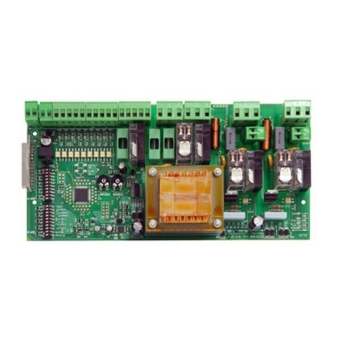
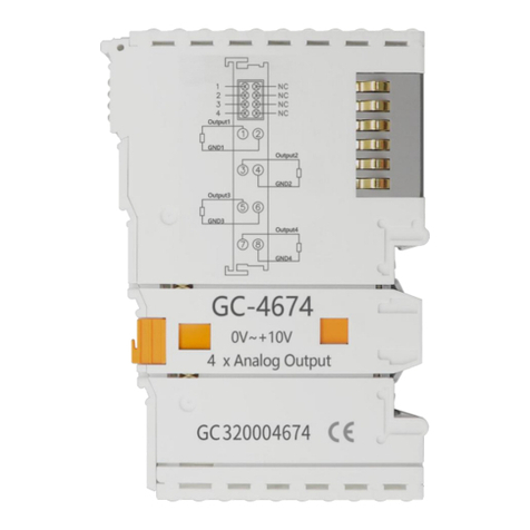
ELCA Amaltea 2 User manual

This manual contains very important instructions for the installation, and use of this control board mod.
Do not install prior to reading this manual, the best results depends upon the correct application , installation.
We the manufactures of this product declines any responsibility in the case of an incorrect installation or improper use ,
And should be installed by a qualified person. This product has been created by keeping the strictest safety norms following
EC directives : CEE73/23, CEE89/336, CEE93/68, CEE89/106, CEE89/392.
AMALTEA-2.
STOP
P1
Led ON
OK
RECEIVER
DIP
Led
ABC
Courtesy Light
Flashing light
Motor
Com
220Vac
Antenna
Stop
Button.
Start/Stop
C
B-
A
- Only rolling code
Theft proof’s function
- Tampering
Off ON
1 Pause
2 Times
omnipolar
230V 50Hz
4512345
TX
24 Vac
Photocell
Photocell
TERMINALS CONNECTION
1-2
3-5
4-5
6-5
7-8
9-10
11-12-13
14-15 power supply 230 Vac - 50 Hz )
11-14
ANTENNA terminal n.1=RF
STOPcontact, normally close.
PHOTOCELL contact, normally close
START/STOP contact, normally open
output 24 Vac max feeding 2 photocells
courtesy lamp contact (max 5A-230V) free voltage contact
connection for monophase motor 500W max (terminal n.11=common)
flashing light connection 230V-25W
(TERMINAL 14=NEUTRAL
!
FOLLOW THESE INSTRUCTION CAREFULLY !!!
!ATTENTION !!
During the installation it’s important to have a switch with
contact opening of at least 3mm that assurse an omnipolar
disconnection of the board to the current network . Procede
with a correct motor grounding.
Control board for
rolling-shutters and
blinds’ automation with:
-rolling code
-cortecy lamp contact
Amaltea 2
Soldering bridges
RX
1
Switch
ELCA snc Tel. 0039 0734 608484
Via Malintoppi, 32 Fax 0039 0734 605080
ITALY web: www.elcasnc.com
This manual has to stay with the equipment at all time, must not remove!
!FOR SAFETY REASON A SAFETY DEVICE
MUST BE USE WHEN USING THIS REMOTE CONTROL

FUNCTIONS
Switch
omnipolar
230V 50Hz
R2
Off On
1 Pause
2 Times
Dip
P1
R1
P1 Off On
1 Pause
2 Times
Dip
R3
2
A - RADIO CODE PROGRAMMING (A code different from basic code)
possible to program different standard codes or
It’s
A1 - Set a new code in hand set
A2 - Push the white button on the main PCB ONCE THE should
come on.
A3 - Send an impulse or signal from hand set from a minimum distance of 0,5
meter the OK led should go out for about 0,5 second, indicating the
memory has accepted the new code. It’s possible to store more codes in the
memory, when the memory becomes full the OK led will falsh 2 times to
indicate the memory is full.
A4 - To leave the programing procedure press twice, the OK led goes out
A5 - If you need to cancel codes from the memory :
Press and hold down turn power off and after a few seconds still
holding down switch power back on the PCB is now back to
factory setting
61 15 rolling codes
P1 OK LED
P1
P1
P1
P1 Led OK
A2
Led OK
50 cm
Turn off
0,5 sec
A3
P1
Led OK
2 impulses
A4
P1
Switch
omnipolar
230V 50Hz
A5
B- STOP CODE PROGRAMMING
<<< not available at the moment >>>
P1 Led OK
B1
Led OK
STOPSTOP
3
5
B2
P1
Led OK
2 impulses
B3
AMALTEA2 is the appropriate control board to operate motors with incorporated limit switch,
you’ll find it ready having a BASIC PROGRAM given from the factory :
> working time = 30 seconds
> radio code in memory = dips 1-3-5-7-9 ON channel n.1
( transmitter’s base code )
> without automatic closing
( courtesy lamp timing = 3 min.)
R-
It is possible to return to the BASIC CODE or PROGRAM :
R1 - Switch ELECTRICAL supply off turn dip switches 1 and 2 ON
R2 - While holding P1 down turn power on
R3 - The OK LED goes off for about 1 second at this time release P1 and
turn dip switches n.1 and n.2 off
( the program is back to basic code)
RESET
B1 - Push the button The OK led goes on.
B2- Open the stop contact (terminals 3-5) send a code from the
hand set, the OK led goes off for 1 sec.
B3 - For came out of programming push 2 times the button
P1.
P1.

3
C- COURTESY LAMP CODE PROGRAMMING
(if you need to switch the lamp by the transmitter)
C1- push two times the button the led flash
C2- send a code (not yet in memory) from the transmitter, the led stop
flashing for 0,5 seconds.
It’s possible to memorizing more codes.
- To erase the lamp codes follow the step
P1 OK
A-5 or a RESET
NOTE : Programming the code to command the courtecy lamp doesn't exclude its lighting
for 3 min at every movement.
P1
2 impulses
Led OK
Flashing
C1
Led OK
Turn off for
0,5 sec
C2
D- WORKING TIME PROGRAMMING
Off On
1 Pause
2 Times
Dip
Led OK
2° impulse
1° impulse
Start/stop
5
6
D2
Off On
1 Pause
2 Times
Dip
Led OK
E- PAUSE TIME PROGRAMMING (only required on automatic closing)
Off On
1 Pause
2 Times
Dip
Led OK
Off On
1 Pause
2 Times
Dip
E1
(Only use if the door takes longer than 30 seconds
--- place the door in closed position ---
D1 - turn dip switch n.2 on the board to on the
OK led should be on
D2- Send an impulse from hand set or by a switch with the
connected on 5-6 on the PCB, the door should start to open if not,
swap wires n.12 and n.13,and try again, the door should open, when
the door is fully opened give a signal again from hand set, or press the
switch to stop door,then turn off dip switch n.2 off on the PCB.
(Max time = 4 minutes)
D3- set the dip n.2 in OFF position
E1- turn on dip switch n.1 in ON (the OK led comes on) leave it on
for the desired time, max 4 minutes, turn off dip n.1 photocells
should be used when using this function.
Replace dip n.1 in OFF position.
OTE : If you want the door to stay open for a longer period in this mode, send a signal
from hand set the door will stay open untill you send another signal.
N
D3
D1
To open)

4
F- SPECIAL FUNCTIONS
ABC
F1
ABC
F3
FEATURES
> power supply = 230vac >output for single phase motor 500w max
> low tension input 12V > output 24 vac (power for 2 couple of photocells)
> extractable self-learning receiver, frequencies 434mhz
> ABS autoextinguishing box with closing screws Ip54 SIZE: 130-45-70 mm
ABC
F2
F1- if a solder bridge is across point “C” the control board will operate a
Rolling code, but this should only be done by a qualified person.
F2- to set
Solder a bridge across position “B” as shown in diagram again this should
be done by a qualified person, the customer may use a code to that blocks
any function,the first code memorized will have the theft proof function,the
OK led flashes twice.The board will only accept the theft proof code if the
door is in the closed position.
THEFT PROOF.
When a signal is recived the door will open for a few seconds and then close, this proves that
the theft proof function is activated.
When using the hand set again with the theft proof code the door will operate in the normal way.
- If a rest or code change is attempted while in THEFT PROOF the board will shut
down for its own protection, to start and go back to base code, the bridge on “B” must be
desoldered by a qualified person.
To come out of the theft proof function :
switch off power remove the bridge on “B” with a soldering iron, again
this can only be done by a qualified person, power back on and go
through the set up procedure.
ATTENTION !!!
F3 - TAMPER PROOF
If a bridge is soldered across “A” the tamper proof fuction is activated.
The installer has installed the board to memorize a code that lets you operate the door in a normal
way, but you can not change to another programe without removing bridge “A” again this should be
carried out by a qualified person.
this sets the modul
back to work as normal. This must be carried out by a qualified person.
: If both bridges are in operation, the first code takes preference the tamper proof takes
priority over theft proof, first code and then the second code will activate the board in this order.
A”,
NOTE A-B
- the first code programed will have the function, the OK led will flash 3 times.
- when you send a new code, this function is aborted the OK led will flash 4 times
>> to remove the function:
Switch the power off, remove board from box, remove solder on bridge “
TAMPERING
TAMPER PROOF
WARRANTY
ELCA devices and accessories are guaranteed for a period 24 months after production, whose date is printed
on each items. ELCA will replace or repair its devices, provided that they are returned to our plant.
In order to check the actual functioning of the returned pieces, they will remain the property of the manufacturer.
The warranty does not include damages due to any incorrect use such as : non fulfilment of the instructions detailed
for each device. Moreover, warranty dpes not cover any damage due wrong tension supply and any other reason
for wich the manufacturer cannot be made responsible. Any device returned must be delivered to ELCA with carriage
paid will be back with freight collect. Warranty validity ceases in case of the customer’s non fulfilment of payment.
Rev. 01 Issued by Baglioni Simone 27/10/04
Table of contents
Other ELCA Control Unit manuals
