SDS CPi-2 User manual

1
SDS CPi-2
IGNITION
Coil pack ignition for non-certified aircraft engines with automatic battery backup.
Software version 1.6 Apr 20, 2020
Panel mountable Programmer & Display Single board CPi-2 ecu
Dual board CPi-2 ecu
4 cylinder Coil pack 6 cylinder Coil pack

2
For 4,6 and 8 cylinder 4 stroke applications.
Please read the entire manual before beginning installation.
Any text in bold or underlined is especially important and this has been learned from feedback and
troubleshooting from over 25 years in this business.
System Variations
The CPi2 is available in multiple configurations:
Single board ecu driving 1 coil pack on a single plug engine.
Single board ecu driving 1 coil pack in conjunction with a magneto or other ignition on a twin plug engine.
Single board ecu driving 2 coil packs on a twin plug engine. (redundant coilpacks, but non-redundant cpu board).
Dual board ecu for twin plug engines, with each board driving its own coil pack.(fully redundant)
System Description
The CPi2 unit is a microprocessor based ignition unit designed to trigger the supplied waste-spark type coil packs
either with built in ignition drivers or ignition driver modules mounted nearby the coil pack. The CPi2 cannot drive
traditional ignition coils directly without a driver module.
The Cpi2 can automatically switch over to battery backup power if the main 12 volts bus voltage goes above or
below set thresholds, or if 12 volt mainbus power is lost.
Dual board CPi2 units have two identical boards double stacked in one box. The boards do simple communication
between each board and each knows if the other goes offline and can act accordingly. Throughout the manual the
two boards in the Dual board CPi2 are referred to as “A” Primary or “B” Backup. Really they both function the same
at all times, and if one board fails or loses power the other board should keep the engine running. The programmer
display and keypad unit can access each board in the dual board system by pressing the PROG key on the
programmer unit. This is explained in greater detail later in the manual. On Single Board ecu units, the PROG key
serves no function.
Engine spark timing is fully programmable for both RPM and load (manifold pressure or throttle position). Triggering
is accomplished with magnets attached to the crankshaft and a Hall Effect sensor fitted to the engine case. As such,
timing variations relating to gear lash or harmonics are eliminated. Two triggering magnets are used on 4 cylinder,
three triggering magnets are used on 6 cylinder applications, four triggering magnets on an 8 cylinder. One sync
magnet is also used to synchronize the computer with the engine so the computer knows which coil to fire first. As
each magnet passes the Hall sensor, a pulse is sent to the CPi2. The CPi2 determines the exact rpm and manifold
pressure, sums the programmed spark retard values and calculates the appropriate delay for the specific conditions
at that instant, then triggers each coil to fire at the precise time. Each coil fires two cylinders simultaneously, one
cylinder on compression, the other on exhaust.
Once the system has been calibrated using a timing light by setting the MAGNET POSITION value, the gauge1
screen will accurately display the actual ignition timing in degrees BTDC in real time. Programming can then be
accomplished in the simplest possible terms to understand.
Hall sensor (adjustable type) Hall sensor Twin Hall sensor for
(non-adjustable type) Dual board CPi2 units

3
Part 2 Component mounting and wiring
ECU Mounting
The gold ecu should be mounted in the interior of the aircraft, not in the engine bay. The ecu is not waterproof and
should not get water inside. If possible, mount the ecu with the connectors facing downward, so that if water runs
through the firewall and down the wiring it will drip off at the lowest point where the wiring turns upward to enter the
ecu. Ecu height dimensions, Single board 1.085”, Dual board 1.785”. Note that the ecu has fuses on one side of it
so mounting so the fuses are accessible is wise.
CPi-2 ecu dimensions:
Programmer mounting
Mount this in a visible area on the panel. Its is
important to be able to view the programmer in
the event that there is a problem in the system.
The LCD display is rated as sunlight readable,
but it would still be better to have the screen
shaded if possible to aid in viewing. Note the
programmer has a chassis ground wire on the
rear, please connect this to protect the
programmer from static discharge. Damage
could result without the programmer body
being grounded. Allow 3.75” rear clearance
from the back surface of your panel for the
cable exiting the rear of the programmer.
Cable exits the rear about 3/8” above the rear
center of the programmer unit.
Programmer panel cutout
dimensions.These are exact dimensions
of the programmer so add .010 to.020” around
the octagonal cutout for some clearance.

4
Wiring Installation and connections
Photo showing wiring connections to a Single board CPi2 ecu:
Dual board CPi2:
Like Single board details above, but times two.
Power switching +12 volt wires to Cpi2, Purple and Red wires, Breakers and Switches:
Single board CPi2: One Double pole switch and two breakers are required. 2-5A for the purple wire, 10-15A for the
Red High current wire.
Dual board CPi2: Two Double pole switches and four breakers are required. 2 x 2-5A for purple wires, 2 x 10-15A
for the Red High current wires.
It is important to switch both purple and red wire for proper operation and to also keep the backup battery
from slowly draining current when the system if shut off. Also allows proper power-off operation.
Purple wire current draw is less that 200mA.
The Red 18ga wire on the 12pin coil harness plug. This is the high current source for coil pack power +12volts. With
SDS supplied coilpacks, average current draw is less than 6 amps below 5000 rpms. We do need the 10 to 15 amp
rating for a safety buffer and also because current spikes between 4 and 8 amps for a few milliseconds with each

5
spark event. Average current draw can be higher depending on coilpack brand and the Coiltime setting, and when
engine RPM’s get up above 4000RPM.
VPX Breaker system Not recommended or Use at your own risk. Purple wire should be okay since current is low
and constant. The Red Hi current wire is where the risk comes and if connected to a VPX breaker system, set this
breaker as high as possible as the VPX may trip due to the current spikes that occur in the coil power circuit. Don’t
set the VPX for 10amps because it could false trigger. This is really just protecting against a short in the wiring. The
CPi2 has coil fuses on its coil power outputs for proper current protection and also traditional fuses won’t falsely
blow due to current spikes, they see the average current instead.
CPi2 ECU Ground wires:
Single board there are two ground wires:
One ground on the Coil Harness 12pin plug.
One ground on the 14 pin main harness connector.
Note on Dual board ecu’s there are four ground wires.
Connect these ground wires to separate ground lugs on your grounding bus for better redundancy. No need to run
the ground wires direct to the main battery, unless you have no grounding bus installed. Make sure connections are
good and surface is clean and free of rust or paint. Poor grounds will cause many problems and problems may only
show up at higher engine rpm’s, as electrical current demand increases. Do not run ground wires to the engine
block.
Runup/magcheck yellow and gray wires
Single board running one coil pack: Connect only the gray wire to your kill switch. Gray wire goes to L terminal on
aircraft switches. The yellow wire, don’t install. Typically in this case the 2nd spark plugs will be run using magnetos
or other ignition. Disconnect the old magneto kill wire off the keyswitch L and connect the CPi2 gray wire to L.
Single board running two coilpacks: Insert the Gray in the lower right corner position of the 14 pin main connector.
Insert the Yellow wire in the position just above the gray wire. Connect Gray to L on aircraft key switch, Yellow to R
terminal on aircraft key switch.
Dual board running two coilpacks, use this photo below:
Install yellow and gray wires as shown in the photo.
Insert the gray wire terminal into the lower right position of
the upper main harness connector.
Insert one of the yellow wires terminal into the lower right
position of the lower main harness connector. Insert the
other yellow wire into the upper right position of the upper
main harness connector. We need the two yellow wires
connected together due to system complexity.
Note, the upper is primary closest to enclosure lid, lower
is closest to the mounting flange.
Connect the Gray wire to L on the aircraft key switch, or to
your toggle kill switch labeled L.
Connect the Yellow to R on the aircraft key switch, or to
your toggle kill switch labeled R.
If using toggle switches the other terminal of the toggle
switch must be connected to ground.
It may be wise to mark the upper and lower main harness
plugs so they do not get swapped in position if they are ever unplugged in the future.
Installations without the aircraft type key/mag switch
If you don’t have a typical aircraft key/mag type switch, you can wire up yellow and gray to one or two normally open
momentary push switches or toggle switches to kill ignition which will then shut down the engine. Remember turning
off Mainbus power to the CPi2 just forces it over to backup battery power so your Mainbus or ecu power switch will
not shut off the engine. Read on though, there is a window in the programmer that can shut down the engine

6
although it’s a bit less convenient since you have to find that window then press the minus key. Not so good if you
need to shut off the engine quickly for some reason.
Optional Backup Battery mounting kit, and wiring connections
Mount the backup battery cnc holder to the airframe. The battery kit pictured
here, there are 4 countersunk mounting holes in the bottom of the battery
bracket using #10 flathead screws. Do not mount the battery close to a hot
surface where there would be exhaust heat on the other side of the
aluminum. AGM batteries can be mounted in any orientation since they do
not leak. There is no need to switch the battery power to the CPi2. When the
CPi2 is powered off the current drain on the battery is only 0.0000016A, on a
Single board and .0000032A on a Dual board CPi2. Route the wire harness
from the battery to where the ecu is located and plug it into the left side of the
ecu as shown in the ecu photo below.
Using your own backup battery If you are connecting to your own
already installed backup battery then you will need to mount one or two ATC
fuse holder(s) close to your backup battery. One fuse holder for single board,
two for dual board ecu’s. Battery wiring harness-red to fuse, then fuse to
battery plus, black to battery minus. For the dual board CPi2 the same
applies for the 2nd battery harness. 15 amp ATC fuses should be used for the
backup battery.
Battery grounding, important. If your backup battery is powering devices other than the CPi2, then you
should connect the battery minus to your grounding bus or chassis ground. If the battery is only being used for the
CPi2, there is no need to chassis ground the battery, as it will ground via the CPi2 ecu and harnesses.
Green Tachometer signal output wire
This wire outputs a 12 to16 volt square wave signal to drive instrument panel tachometers. Be sure your instrument
can accept a 12 to 16 volt signal before you connect this wire, most should, but consult your manual.
Use the green wire from the primary main harness.
For Garmin G3X, connect to pin 8 J243, no pullup resistor is required, since there is a pullup resistor in the CPi2.
For Advanced Flight Systems 5000, Connect to pin33 electronic ignition input.
For Dynon skyview, connect to pin32 Standard RPM input wire. For Dynon, if you have removed a magneto, there
could be a 30K or similar resistor installed in the wiring which they require, but for the CPi-2 you must remove this
resistor since the CPi-2 tach output peak voltage is equal to your main bus voltage (less than 15). If the CPi-2
switches to backup power then peak tach signal voltage will equal the backup power source voltage.
On dual board CPi-2’s the backup harness green tach wire could be used for a secondary tach or instrument panel
or be unconnected. Connect to Dynon pin 33 or G3X pin 6 on J243
Programmer DB9 cable
Connects the ecu to the programmer. This is just a generic cable straight through type cable. The Dual Cpi2 unit
has only one programmer cable, which is all that is needed. A switching board spans the two main boards inside the
dual ecu allow the programmer to access each board separately by pressing the PROG key.

7
Coilpack wiring harness
Colors/function
Red supplies coilpack 12 volt power, black supplies ground, other wires are the
spark signals from the ecu cpu chips. Signal wires are orange, white, blue(6&8cyl),
gray(8cyl only).
When you unpack the system, these wires will not yet be installed into the coilpack
harness 12 position ecu white connector. These wires will usually be 4 to 10ft in
length and they need to be pushed through the firewall from the engine bay side of
the aircraft, and routed to the CPi2 ecu. Route these in to verify they are long
enough and then you can insert the end terminals into the white 12pin connector
as shown here in the photo. Be careful the terminals won’t come out without an
extractor tool! When inserting terminals, crimp folds must be toward the top of
connector and top is where the latch is.
Single board CPi2 driving two coilpacks, the upper row will also get the same wires
from the second coil pack. Not applicable to 8cyl, only 4&6 cyl.
Dual Board CPi2 driving two coilpacks will look like the photo on both boards.
Please don’t cut and install a connector at the firewall, this just adds another point
of stress/failure.
Coil pack mounting
For common Lycoming and Continental installations refer to supplement manuals to mount coil packs.
Generic mounting: Both types of coilpacks pictured on the front page of the manual are able to be mounted on the
engine if needed. Do not mount coil packs within 8 inches of exhaust pipes. Shield coilpacks from infrared exhaust
heat also.
Hall sensor cable(s) and ecu connector
From engine bay, route through the firewall to the gold CPi2 ecu. Do not route
hall sensor cable alongside spark plug wires. Keep away from spark plug wires
by at least 2 inches. Keep away from hot exhaust pipes, and shield with fire
sleeve if necessary to reflect infrared from exhaust. Use a grommet at the
firewall and please don’t cut and install a firewall connector, this just adds
another point of stress/failure. Route to the CPi2 ecu and insert the terminals
into the white 4-position connector as shown in the photo.
Important:
Dual board ecu’s will use a dual hall sensor with 2 cables, marked as follows:
The Green hall cable will connect to the “A” Primary ecu closest to the lid.
The Red hall cable will connect to the “B” Backup ecu closest to the mounting flange.
A note about cutting off crimped on terminals
If you have a small excess of wire its much better to loop the extra length vs cutting and crimping on new pins.
We use a $350 crimp tool and other crimpers don’t do the best job. Universal crimper Molex # 0638111000 is okay
but you have to trim the insulation tabs of the terminals about halfway before crimping. The conductor part of the
terminal will crimp good enough using the smallest opening at the tip of the crimp tool. For the above universal
crimper, enter molex part number 0638111000 into Octopart.com to see who has stock and best pricing. Also good
idea to use a short piece of 1/16” heatshrink on each wire of the multi conductor tefzel cables. Put heatshrink just
before crimping on a molex terminal, this helps protect the wire from breaking. Soldering is actually a good option if
crimping is not possible.
8
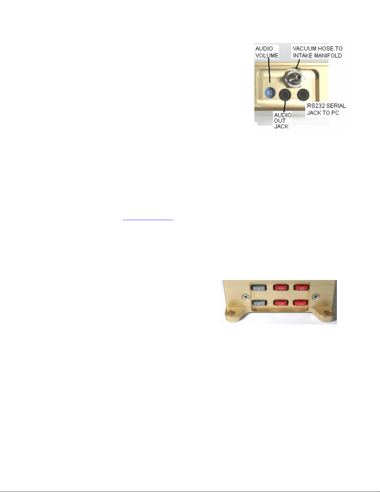
Vacuum hose
Route vacuum hose from engine intake manifold through the firewall to the
CPi2 ecu. Supplied hose is silicone be sure it fits tight onto the intake fitting.
Dual board units will need a “T” fitting near the ecu to split the vacuum signal,
as only 1 hose is needed to the engine, and the vacuum signal is not essential
to keep flying. If you have no central vacuum port on the intake or throttle body,
you could connect the hose to primer port fittings close to the cyl head but use
at least two ports to get a smooth enough signal. Use a grommet at the firewall
and keep away from exhaust heat. If using an automotive throttle plate, best
not to connect to the throttle body unless you are sure the vacuum port
channels down below the throttle plate. On some throttle bodies the vacuum
port may route to just above the throttle plate when closed and the vacuum
reading will be lost at closed throttle.
Audio connection
Connect the supplied 1/8” stereo cable to your audio/mixer intercom aux input. There is a test mode for audio so
you can set the volume, this is explained elsewhere in this manual. Audio will only come out 1 side of your headset.
It can be made to come out of both sides, L and R, with a jumper installed inside the ecu, email us if you need to do
this. For dual board ecu’s, just connect your audio cable to the Primary ecu(closest to the lid). A fault in the backup
will be relayed via the Primary. In the event the Primary board is dead there will be no audio warning. You could
connect the Backup to your audio system if you still have an extra audio input available.
RS232 connection
This is an optional item upon purchase. You can connect the CPi2 to a windows PC USB port to log data. We have
a custom cable manufactured for this application. If you don’t have this cable, you can order it by contacting us via
email or phone. 403-671-4015 or ra[email protected]. You cannot program the CPi2 via a PC at the present time.
Logging can capture up to 4 hours of data, RPM, timing, voltages, manifold pressure etc. Also Logging will
download all the settings in the CPi2 so you can view and print them.
On dual board ecu’s you can connect the cable to either Primary or Backup boards, whichever is of interest. On dual
board ecu’s currently the PC logging will only download settings from the ecu board that the cable is plugged into,
but a future version will download settings from both boards. This will take more development time.
ECU Fuses
In the photo showing the dual board ecu, the left side fuses are for
ecu power and rating is 2 amps. The middle and right side fuses
are for coil pack power, rating is 10amp. Fuse type is Blade Mini.
The single board ecu only has one cpu fuse and 2 coilpack fuses.
The 2 amp will blow if the internal crowbar activates when mainbus
voltage is above approximately 25 volts. Coilpack fuses are there
as extra defense to protect the switching circuits in the CPi2.

9
Part 3. System Setup and settings less likely to be
changed:
It is a good idea to confirm all these settings, many of which will not need to be changed.
LOP MAX MANIFOLD PRESSURE
LOP, Lean Of Peak ignition advance will not occur when engine manifold pressure is
higher than this setting, even if the LOP is activated and the LOP LED is lit up.
Typical setting is around 25”Hg Absolute. If you don’t want the Lop advanced timing at
high manifold pressures then you can lower this setting some more. This effectively
blocks the LOP advance at lower altitudes when at full throttle.
# Of Coilpacks
New for Ver1.4, this window only appears on Single board CPi-2’s. If you have only 1
coilpack then the setting needs to be 1. If your Single CPi-2 is driving two coilpacks to
run all 8 spark plugs on a 4 cylinder engine then this setting must be set to 2. This
window does not appear on Dual CPi-2’s because each board only ever drives a
single coilpack so there is no need for this selection in this case.
Tach Output
With Normal setting tach pulses will be 2 pulses per rev on
4cyl, 3 pulses/rev on 6cyl and 4 pulses per rev on an 8cyl
engine. With 1PPR setting output will be 1 pulse per
crankshaft revolution on all number of cylinders. Use the 1
PPR setting if your instrument panel tach is reading extra high RPM’s.
Battery Charge
Enables or Disables Trickle charge on the Backup Battery. With our recommended
backup battery this option should be set to enabled. With other batteries it could be
enabled or disabled depending on requirements. If another charging method is used
for your backup battery then you should set this to DISABLED.
On Dual board systems: In the Primary board, this is normally enabled. In the Backup board this will default to
Disabled, as the dual board systems cannot allow both primary and backup boards to trickle charge the backup
battery.
Main Battery Type
This is to select the type of main battery in the aircraft
so the CPi2 knows when to switch power over to the
backup battery. In the event of an alternator failure the
CPi2 attempts to run on the main battery as long as
possible before switching over to the backup battery. Important to have this set correctly. Select either Pb for Lead-
acid or Li for Lithium Ion. The number following is Mainbus cutoff voltage when the CPi2 switches over to battery
backup. Select using the plus key.
Backup Battery Type
This is the CPi2 backup battery type. Select either Pb for
Lead-acid and also Pb for AGM(glass mat).
Select Li for Lithium Ion. Each has a different cutoff for
trickle charging.
Mainbus Cali
No photo. If required you can use this to calibrate Mainbus voltage. Incrementing by 1 will increase the reading by
0.1 volts. To get a negative calibration, example –1, you need to enter 255. –2 enter 254 etc.

10
Bakbatt Cali
No photo. If required you can use this to calibrate Backup Battery voltage.
Map Cali
No photo. Offset value used at the factory to calibrate the MAP sensor. Default setting is 5 for the built in map
sensor.
Config1, Config2 (no photo)
Do not change these values. This value may control various functions in software. Change only if instructed to do so
from the factory.
Coil Time
Adjusts the charge time or dwell of the coils in milliseconds. Default is 3.6mS for 4cyl
and 6 cyl coil pack systems. Increasing may help spark if running high boost on
turbo/supercharged engines. Increasing dwell will increase current draw of the coil
pack, and could cause the coil pack/ignition fuse to blow at high rpm. If experimenting
with larger coiltime settings, rev the engine in neutral and monitor ignition current. One way to monitor current is to
pull the coil pack fuse out and substitute your ammeter leads into the fuse socket. Fuse should be at least 50%
greater amperage capacity than what you observe on the meter at redline. Too much Coiltime can cause extra heat
in the coilpack. If using SDS supplied coil packs its best to just leave this at default setting especially on a normally
aspirated engine. Alternate or customer supplied coils/coilpacks should be sent to us for testing to find out what
COILTIME(dwell) is required, as this can be a safety issue because too much COILTIME(dwell) can damage coils
and too short will produce weak spark causing misfires at high throttle. For Turbo/Supercharged engines running
high manifold pressure with SDS supplied coilpacks, higher Coiltime may be needed to fire the spark, try in the 4-
4.5mS range.
Coil Test
This screen turns on coil test by pressing +1, turns off with –1. Remove all spark plug
wires and place them close to ground so the spark can jump.
When turned ON, 1 coil will spark every 32.7 milliseconds. Do not turn this ON
when the plug wires are connected to the engines spark plugs, because fuel
could ignite in the intake manifold. See troubleshooting section.
Err Mask, Err Mask2
No photos. These can be used to block Faults from showing. Email or phone us for help if you need to block a
certain Fault. Default is 255 for both, and this allows all Faults to show and turn on the Fault LED.
RPM Err Cnt
No photo. Currently not used. Nothing to program here.
Burn #
No photo. Serial number of database of software download into the CPi2. Not user programmable.
CPU Identity
Not programmable or changeable this just displays automatic board ID in the system.
Will display Single for single board CPi2, Primary or Backup will display for dual board
CPi2 units. If you are not sure which type of CPi-2 you have this window will identify
the system for you. If you see either Primary or Backup here then it’s a Dual system.
IGN Type
For systems using Coilpack or Coil-on-plug coils this setting must be “Coilpack”.
For engines using a single coil and distributor, then this should be set to “1Coil&Dist”.
Note, we expect sales for distributor engines to be extremely rare.
SW older than V1.4 this was named # COILS, set to multi for Coilpack.
RPM Range
Allows selection of RPM range resolution. 4500, 9750 or 15,000 rpm can be selected.
For most aircraft engines the 4500 setting will be used. For higher revving engines
use 9750 or 15,000.

11
Number of Cyls
Number of cylinders of the engine. 4,6 or 8. Setting is locked during engine running to
prevent an accidental change.
Map Type
74” HG AB will be the aircraft setting, good for normally aspirated and
turbo/superchaged engines up to 74” Mercury Absolute. For automotive applications,
select 22PSI for PSI boost & Inches hg vacuum. There are a variety of other settings
for sensors which can be externally connected for higher levels of manifold pressure.
Gauge Diag1
This screen is used mainly for factory testing, but could also be used for
troubleshooting purposes. This screen allows viewing of critical voltage levels feeding
the coil packs in the system. Low voltage readings can indicate resistance in wiring or
poor connections, breakers and fuses. Losing voltage to the coilpack can weaken
spark so this screen could be useful in narrowing down a problem in the electrical system.
CPi-2’s with serial number 30 and lower, CP should read about 10 to 12 volts higher than the power source voltage,
so 24 to 26 volts is normal here. CPi-2’s with serial numbers 30 and higher, CP should read about 4.5 to 5.5 volts
higher than the voltage power source. This higher voltage is needed for the switching circuitry in the CPi2 unit.
CS is Coil Supply voltage from Mainbus power.
PC is voltage going out to the coil pack positive supply wire of the Primary Coilpack.
BC is the coil pack positive supply wire of the Backup Coilpack.
Only single board units will display both PC and BC readings.
Dual board systems will only show either PC or BC but not both, on the bottom line of the display. Press PROG key
and look for this screen in the backup boards settings to view BC voltage.
If CS is reading zero, then there is no power source to the CPi2 units coil power section and there will be no spark.
Check wiring to the CPi2, check the CPI2 fuses, and also check airframe fuses and breakers. Without coil power
supplied the switching circuits in the CPi2 will switch over to backup battery to power the coilpack(s).
Rev Limiter
No photo. Cuts off spark at the setting shown. Increments are in 100rpm steps.
For Dual board systems, be sure to switch over to the B unit by pressing the PROG key, and set its setting the same
as the A unit. Settings need to match if not the engine will rev to the highest setting of the two.
On Batt Coil Time
This can extend backup battery life by shortening coil dwell time when running on the
backup battery. Time is adjustable but don’t go too low, or the engine can misfire. Also
as the main and backup batteries weaken, spark will weaken so care must be taken
not to shorten the dwell time too much. Less that 2.8mS could be risky. Misfires can
occur at high throttle if dwell time is too short. Also, coils not supplied by SDS may have different dwell time
requirements, so if you’re running an uncommon coil pack, this setting may be different from the 2.8mS default.
Adjust this when doing a Battery Test run and see what the limit is when lowering the setting, but raise the setting
back to a higher setting than minimum. Best tested at full throttle.
Ignition Off Setup
On installations where there is an aircraft type keyswitch
or other kill-switch wired to the CPi2, set this to EXT
OFF. Setting to EXT OFF will disable the IGNITION OFF
–1 KEY window, which could prevent accidental shut
down of the ignition and engine. If there is no kill switch then set this to KEY –1, then the Ignition Off window can kill
the ignition to shut down the engine.

12
Show Hidden Settings
Hides all settings above this point of the manual in the programmer, so in other words the programmer will skip over
the other settings, so if you scroll left using the < key, none of the above will appear. If all above settings are not
appearing then this setting must be NO so change this setting to YES to make all settings appear in the
programmer.
Recommended to just leave this set to YES unless you need to access the RET-ADV/LOAD settings many times.
When set to NO this will speed up access to RET-ADV/LOAD.
Values Lock
Extra protection against another person unknowingly pushing buttons on the system.
Press the plus key + to turn ON Values Lock, then most values cannot be changed.
Some however, are still able to be changed in event of a system problem or
emergency situation.
5 Unlockables are:
1. ON BACK BATT COIL “B” ON(OFF)-allows you to turn back ON the B coil pack in case of poor engine
performance on one coilpack, if it was set to cutoff coilpack B when on Battery power.
2. AUDIO CTRL.
3. BATTERY TEST.
4. RUNUP.
5. IGNITION OFF.
In all other windows, no settings can be changed.
13
Part 4. Commonly changed settings or settings you
might change in flight.
Many of these screens will be used in day to day operation of the
aircraft. These are all located within a few presses of the left or right
arrow keys from the Gauge1 screen.
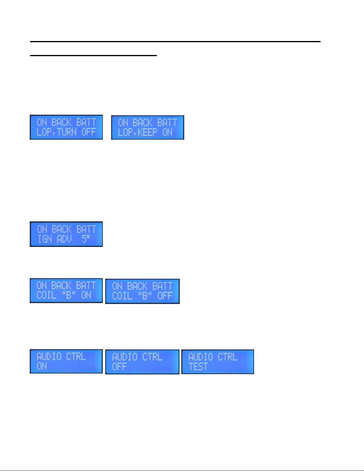
On Backup Battery LOP (Lean Of Peak) turn off or keep on
If the CPi2 goes onto backup battery power, Lean of Peak ignition advance will turn off, or stay on depending on this
setting. If 12V mainbus power is restored, you would need to press the LOP key on the keypad to turn LOP
advance back on again.
LCD Contrast Adjust to help visibility at different viewing angles and at different temperatures.
LCD Brightness 0 through 7, with 7 being the brightest. Settings 0 to 4 are for night time.
On Back Batt Ign Adv
This works in conjunction with another screen, ON BACK BATT COIL “B” OFF(ON).
This will advance ignition timing on coilpack “A” (primary coilpack) if power is on the
backup battery, and if ON BACK BATT COIL “B” is set to OFF. If ON BACK BATT
COIL “B” is set to ON, then this value will display 0 instead of 5 so in other words no
ignition advance will be added because COIL”B” will keep running on if the system is switched onto the Backup
Battery. Extra advance can help with engine power when on a single spark plug.
On Back Batt Coil “B” OFF(or ON)
Only useful for CPi2 systems with two coil packs. If
the engine will run ok with just one set of plugs, then you
can set this setting to OFF, then Coil B will turn off if the
CPi2 loses Mainbus +12V power. This would extend the
backup battery run time by only having to run one of the two coil packs. Works in conjunction with another screen
called ON BACK BATT IGN ADV, which will advance timing on primary coil pack to help engine power when running
on a single spark plug.
Audio Control
The CPi2 system will output a beep warning sound out of the 3.5mm audio output jack whenever there is a fault.
Frequency of the beep sound is approximately every 10 seconds, and the duration of the beep sound is 0.7
seconds. Press + key to change the setting to OFF or to TEST. OFF disables the audio beep, and the TEST setting
can be used to setup volume levels and for troubleshooting an audio problem. If you have a fault occur, be sure to
check the FAULT LIST window to see what is wrong. This screen is just 4 left arrow key presses away from the
GAUGE screen if you need to turn AUDIO OFF in the event it becomes distracting.
14
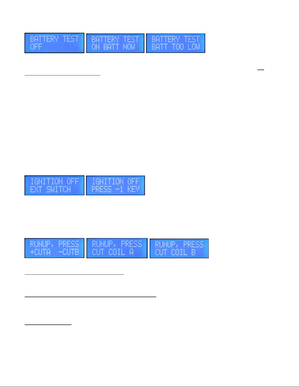
Battery Test
With the engine running, this is a good way to test your backup battery performance, without having to
shut off Mainbus power to the CPi2. Selecting this screen to ON BATT NOW by pressing the plus(+) key, which
then forces the CPi2 power to switch over to backup battery power. When BATTERY TEST is turned on this will
light the Fault LED, which is normal and also turn off the MAIN LED and turn on the BATT LED on the programmer.
Be sure to turn this back to OFF by pressing the plus(+) key again, and the Fault and Batt LED’s should act
as a reminder.
Dual board CPi2’s, the Primary(A) board will send a signal to the Backup(B) board to also switch over to
Battery Test, so there is no need to switch over the programmer to B. With both boards doing Battery Test,
you are getting a true test on both boards and both coil packs running on backup battery power.
If you see BATT TOO LOW message displayed, then this means the backup battery power is too low or not present.
If you restore battery power you will need to refresh the screen by pressing the left arrow then right arrow keys.
It may be good practice to do a battery test before every flight to make sure the battery is functioning. Also
you can scroll 4 > key presses to the right to view Gauge2, Mainbus and Battery voltage while its running on the
backup battery, again be sure to scroll back and turn the Battery Test OFF. Also a good idea to rev the engine as
high as possible when doing this test.
Ignition Off / Engine shut down
Works in conjunction with another screen called
IGNITION OFF SETUP. If there is no engine shut off
switch wired to the CPi2 to shut down the ignition &
engine, then this screen can do it by pressing the
minus(-) key on the keypad. Or this screen can be disabled in installations where there is a traditional OFF R L
BOTH aircraft type key switch, depending on the IGNITION OFF SETUP selection. Best to have this disabled if a kill
switch is wired. It will display EXT SWITCH when disabled and this screen won’t serve any function. This screen will
not power-off the CPi2, see Power Down section.
Runup, (“Mag Check”)
Pressing the plus(+) key or minus(-) keys will cut spark for 5 seconds to either coilpack. Read below for details.
For Single board systems with single coil pack: Press the plus(+) key to cut the spark to the primary coil pack., and
the engine should continue to run on its secondary ignition system. There should be some rpm drop. –CUTB
appears but the minus key serves no function due to only a single coilpack.
For Dual Board and Single board systems with two coil packs: Press the plus(+) key to cut the spark to the primary
coil pack, and the engine should continue to run on the “B” backup board and “B” coilpack. There should be some
rpm drop.
Press the minus(-) key to cut spark to the “B” coil pack, and the engine should continue to run on the “A” primary
coilpack. There should be some rpm drop.
For Dual Board ecu’s: There is no need to use the PROG key to switch to the “B” ecu because the “A” ecu will send
a signal to the “B” ecu to cut spark for this test.

15
Gauge1, Live readings Map, RPM &
Timing
This screen is the instrument panel of the system, showing a live
reading of engine RPM’s, Manifold pressure (MP) (26.6 inches Hg
shown) and current amount of ignition timing on lower left line.
Aircraft applications are in absolute inches mercury. Proper readings
with a typical aircraft engine at idle should be around 8 to 12 inches
with a prop installed.
This is the best screen to be in when flying the airplane since you
can see the most important information, also other important screens
nearby can be accessed with a few presses of the left or right arrow
keys.
If you are in another window, pressing the GAUGE key will display
this window, then if you press GAUGE again you can return to the
prior window you were in before. If you have a FAULT, press
the plus(+) key in this window and see if the FAULT clears.
Gauge2, Live Voltage Readings
Reading of Mainbus 12V supply voltage and backup battery voltage.
The arrow mirrors the LED’s MAIN and Batt. This is one press of the > key from Gauge1.

16
Fault List for CPi-2.
If you have a FAULT, press the plus(+) key in this window and see if the FAULT clears.
This window displays any Faults with the system. A maximum of 4 faults can be displayed. Some faults are latching,
Fuse1,Fuse2, Map sensor and Hall sensor are latching meaning that even if the fault is only for a short time, the cpu
keeps the fault code in memory so it can be seen. Press +1 key to for the cpu to try to clear Fuse, Hall and Map
faults. If the fault was momentary it will clear, but if the fault still exists the fault will remain on display. Other faults
like Voltages, Comms, Other will clear if the conditions change and the particular parameter is within limits.
On Dual board units you may need to Press the PROG key and check the Backup unit and view its Fault window to
see what is wrong in the B board. There is limited communication between dual boards, the Primary “A” board does
not know what the specific fault is with the Backup ”B” board, just that there is a problem.
Fault List chart
Fault will display Explanation
VOLTS Mainbus power weak or no power
BATLO Backup battery weak or not connected or battery fuse blown.
HALL Check hall sensor, magnets, connections and wiring.
CHG P Power switching circuits problem. Water inside ecu box or malfunction on board.
OTHER Primary is seeing a fault in the backup “B” system board. Vice-versa applies.
COMMS Dual board only. CPU boards not communicating, one may have no power.
Fuse1 or Fuse2 Problem with 10amp Coil fuses for coilpack power. Check fuses on side of gold ecu.
Map Map sensor hit high or low voltage limits.
VCOIL Hi current +12V power source low or not present.
If you have a FAULT, press the plus(+) key in this window and see if the FAULT clears.
Fuse1, Fuse2, Hall, Map Need to be cleared by pressing the plus(+) key while in this
window or the Gauge1 window
LOP, Lean Of Peak Ignition advance.
Ignition advance for Lean Of Peak is adjusted using this window.
When the LOP key is pressed and the LED is lit, then there will be
extra ignition advance to help power under leaner fuel running.
Note, that engine manifold pressure must be lower than the
LOP MAX MANIFOLD PRESSURE setting, and engine RPM’s
must be 1100 rpm or higher for the extra ignition advance.
On Dual board ecu’s if you change this setting, make sure you also press the PROG key and change the
setting in the “B” backup ecu so the timing matches on both the “A” Primary and “B” backup ecu’s.
Knock Retard and Knock Sense
Airplanes, make sure Kock Retard is zero and
Knock Sense is 1. Knock retard is the amount of
degrees per knock event. Knock Sensitivity
adjusts the gain of the knock sensor circuit.
Crank Retard
Extra ignition retard needed for engine cranking. This amount doesn’t show up in
gauge mode, but it does occur if you watch using a timing light. It helps correct
timing as the engine slows under compression during cranking. This retard
disappears above 120 RPM’s. Keep at 15 minimum for all types of engines.

17
RPM Ignition
This is where the main ignition timing is programmed. There are 38
Rpm ranges in total just 4 are shown in photos above. The first 3
are always 500,750 and 1000. Above that RPM steps are in 100,
250 or 400 increments, with RPM RANGE settings of 4500, 9750,
or 15,000 respectively.
Ignition Programming
Ignition timing requirements differ widely between various types of
engines and fuels used so we can only offer general guidelines for
ignition values. SERIOUS ENGINE DAMAGE CAN OCCUR with
improper values entered. Excessively retarded timing can cause
high exhaust gas temperatures while advanced timing can lead to
pre-ignition and detonation. Default values may not be correct
for your engine!
Ignition Advance and Retard vs.
Load(manifold pressure)
These 64 settings allow programming of ignition retard or advance
with reference to load on the engine. Load information is from the
MAP sensor. RET refers to retard, and ADV refers to advance.
RETard reduces timing, usually done at higher MAP to prevent
detonation (left photo above).
ADVance adds to your timing, usually at lower MAP to help fuel
economy (right photo above).
ADVance will be added to RPM IGN, RETard will get subtracted
from RPM IGN.
If too much retard is programmed, power output from the engine
may be reduced significantly.
Advance may be useful to improve fuel economy. Advance can be
programmed by pushing the minus key.
To the right is a generic example timing map to show how
RPM Ignition and the RET-ADV/LOAD work together. Some
advance is used under low MAP to help fuel economy, and some
retard at high MAP to help prevent detonation. The CPi2 will read
engine RPM and lookup the RPM timing for that RPM range. Next
the CPi2 will read the Manifold pressure via the Map sensor, and
lookup the RET-ADV for that Manifold pressure range. Software
uses the RPM Ignition amount and adds Advance or subtracts
Retard from the manifold chart to get the final timing.
Example: RPM is say, 1600, RPM Igniton=23, and lets say manifold
pressure is at 21.9” where we have 3 deg Advance, so total timing
will be 23+3Adv=26 degrees. Another example, RPM=1500, RPM
Ignition=23, Manifold pressure at 38.1”, 4 Ret, so 23 minus Retard
of 4 = 19 Degrees total timing.

18
Aligning the Hall sensor and magnets
MAGNET SEEN WINDOW
Safety note, Disable power to coil pack(s) before doing hall alignment or checking.
Rotate the crankshaft very slowly by hand using appropriate tools.
LCD display, top line is used for checking trigger magnets. Bottom line is used for checking the sync magnet.
If CNC supplied brackets are used with the system, alignment is not adjustable but it is still required to verify that all
the magnets are being seen by the sensor, so the ignition will operate properly. Watch for magnets installed
backward which will then trigger the wrong sensor element in the hall sensor.
If the slotted type sensor is used then you will have to move the sensor inward or outward for best alignment to the
magnets.
Alignment Steps for slotted type sensor:
1. Best to rotate the crankshaft so that a trigger magnet is closest to the sensor.
2. Have the mounting bolts loosened slightly and slide the sensor in or out until the window shows TRIG YES. YES
means the CPi is seeing the trigger magnet.
3. On adjustable sensors, slide the sensor back and forth and try to find the mid-point where the Trig shows YES.
4. Tighten the hall sensor mounting bolts. Check remaining trigger magnets and also the sync magnet.
Each magnet should be seen for at least 2 to 3 degrees of crank rotation.
Note: This window has no use once the engine is running, since the sampling rate of the programmer is only about
twice per second. You will see NO in the display when running with the rare occasional flicker of YES for a magnet
being seen while software happens to be updating screen data when the magnet is over the sensor.

19
PROGRAMMING THE CPi-2
MAGNET POSITION, THE MOST IMPORTANT SETTING!
Initial Setup - VERY IMPORTANT
This is how timing is calibrated. This step requires a timing light. The
best timing light to use, is one that does not have a delay knob. Delay
lights may not work properly with multi-spark ignitions or with multi-
coil/waste spark ignitions. If you only have a delay type light set the
delay to 0. The crank pulley and timing cover must have timing marks
on them. The timing light inductive pickup clamp can also be
connected onto the ground wire of the coil pack unit if clipping to the spark plug wires does not work well. Magnet
Position is adjustable from 50 to 110. If you find you need to exceed the limits of magnet position, then this means
the magnets are mounted in the wrong locations and will need to be redone.
For Lycoming engines with dual board CPi-2s, set Magnet Position on the Primary ECU (green Hall cable) to 97, set
Magnet Position on backup ECU (red Hall cable) to 88. On single board CPi-2s, set Magnet position to 92. On
other engine types, consult the supplemental manual for specific settings for Magnet position, as this will allow the
ignition timing to be fairly accurate on the first startup. On engines other than Lycoming, you still should connect a
timing light to verify the timing is correct though to be safe as mistakes could be made during the magnet mounting
process.
For custom installations where the installer has fabricated their own Hall mount hardware, then following procedures
here are very important because ignition timing could be far from target and engine damage could occur if Magnet
Position calibration procedures are not executed.
To be even more careful it may be best to disable fueling to the engine and crank the engine while watching a timing
light to see if the timing is approximately correct. Somewhere between 15 degrees BTDC to 0 degrees or even if its
after 0 degrees is acceptable. If you see timing more than 15 degrees BTDC then you can increase the Magnet
Position number and this will move the timing closer to Top dead center which is safer for the engine.
This step should be performed as soon as the engine is fired up and idling. Ignition timing is meaningless
without first setting the MAGNET POSITION parameter properly.
STEP 1. Set RPM Ignition values from 500 thru 1500 RPM’s all to 10 degrees. If you have no 10 degree mark on
your prop hub and no pointer you may have to make these.
STEP 2. Make sure that all IGN RET-ADV/LOAD values below 30 inches are 0.
STEP 3. Start the engine and keep it running below 1500 rpm.
STEP 4. Connect a timing light.
STEP 5. Change the MAGNET POSITION value until the timing light reads 10 degrees BTDC.
Now some people may have difficulty and say, “But I don’t have a 10 degree mark, how do I line up the timing?”
One way is instead to program RPM ignition numbers to zero instead of 10. Then adjust Magnet Position until the
timing light is flashing at TDC. Some engines may need the throttle opened a bit more with zero degrees of timing.
Once the MAGNET POSITION is set, it does not have to be changed again- it is only to tell the ECU what the
"distance" between the #1 MAGNET and Hall sensor is. Once the above 5 steps are completed, you can program
any of the ignition values.
For the slotted type sensor, MAGNET POSITION may need to be adjusted if the Hall sensor is removed for engine
repairs, so after it is installed again, then the above procedure should be completed, so the ignition timing is the
same as before.
Important!
On Dual board CPi2 units you will have to do this for the Backup unit also, and the

20
Magnet Position value will end up to be different from the primary board due to dual hall
sensor used on the dual board unit.
Table of contents
Popular Control Unit manuals by other brands


Mitsubishi Electric
Mitsubishi Electric MELSEC iQ-R Series user manual

Woxcon
Woxcon IPA-C user manual

BENDIX
BENDIX TP-4 TRACTOR PROTECTION VALVE manual

Aprimatic
Aprimatic ROLL 500S installation instructions

Ametek Land
Ametek Land LSP-HD installation guide

MOGAS
MOGAS T Series Installation, operation and maintenance manual


