ElcoBrandt 2004 solo User manual

STEAM OVEN
2004 solo model


STEAM OVEN 2004 SOLO MODEL
Technical training CONTENT
- 3 -
CU5-VAP2004-001UK-03/05
1 - GENERALS..............................................................................................................................................................4
1.1. - Overview ...........................................................................................................................................................4
1.2. - Control panel.....................................................................................................................................................4
2 - FITTING....................................................................................................................................................................5
2.1. - Build-in the oven ..............................................................................................................................................5
2.2. - Electrical connection .........................................................................................................................................6
2.3. - Technical features.............................................................................................................................................6
3 - USING.......................................................................................................................................................................7
3.1. - Setting the time .................................................................................................................................................7
3.2. - Possible functions .............................................................................................................................................7
3.3. - Locking the control panel..................................................................................................................................7
3.4. - Cleaning the channel ........................................................................................................................................7
4 - GENERAL PRINCIPLE............................................................................................................................................8
5 - STUDY OF THE COOKING CYCLE........................................................................................................................9
6 - AIR FLOW ..............................................................................................................................................................10
7 - DIFFÉRENT COMPONENTS.................................................................................................................................11
8 - DIAGRAM...............................................................................................................................................................13
9 - TEST PROGRAM...................................................................................................................................................14
9.1. - Important instructions......................................................................................................................................14
9.2. - Preliminary steps ............................................................................................................................................14
9.3. - Run of the test program ..................................................................................................................................14
STEAM OVEN 2004 SOLO MODEL
Technical training
GENERALS
- 4 - CU5-VAP2004-001UK-03/05
1 - GENERALS
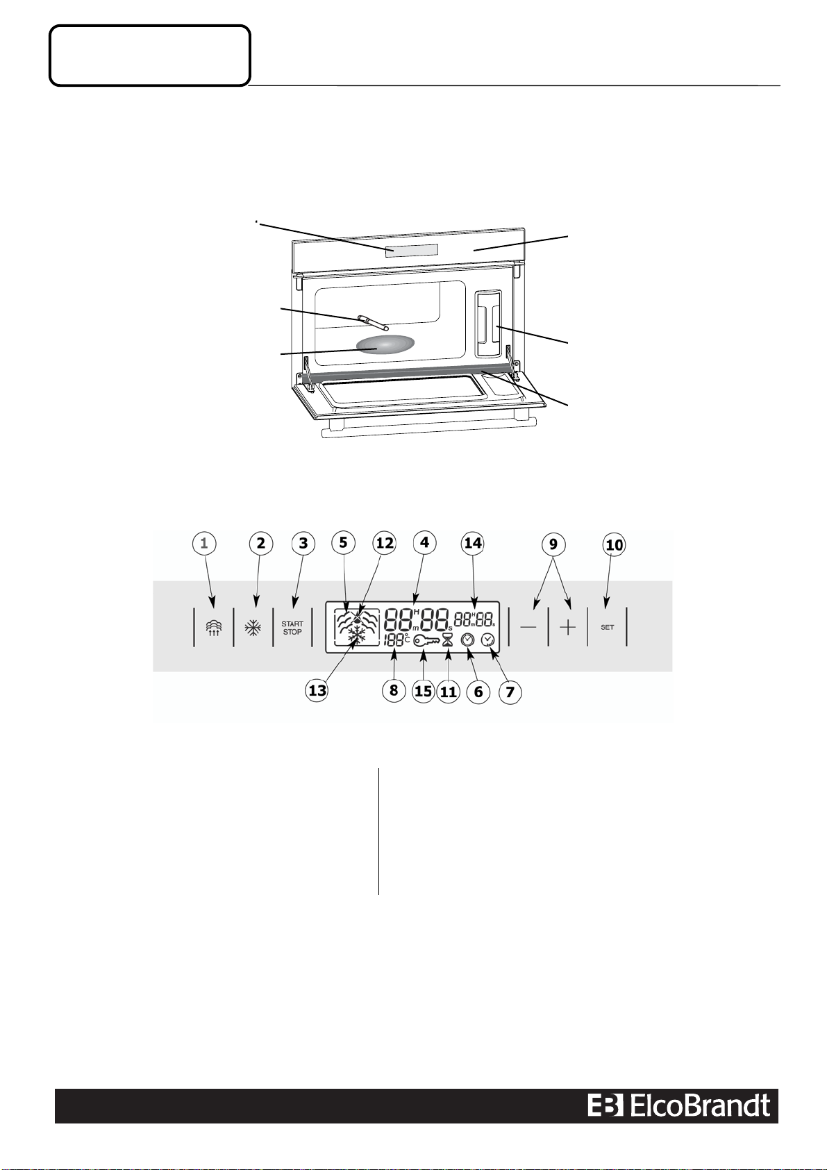
1.1. - Overview
1.2. - Control panel
The order and the number of keys depend on the reference.
The appliance is equipped with a single electronic board which manages at the same time, the control and the
switching of the power elements.
Display
Water supply tube
Steam generato
r
Control panel
Tank
Channel
1. Steam cooking control 9. +/- controls for timer
2. Defrosting button 10. Selector button
3. Start/Stop control 11. Autonomous minute timer
4. Time and delay display or timed period 12. Water circuit problem signal
5. Steam cooking symbol 13. Defrosting symbol
6. Cooking time symbol 14. Display of the cooking period or delayed start time
7. End of cooking time symbol 15. Control panel locked
8. Tem
p
erature dis
p
la
y

STEAM OVEN 2004 SOLO MODEL
Technical training INSTALLATION
- 5 -
CU5-VAP2004-001UK-03/05
2 - FITTING
2.1. - Build-in the oven
The oven has a high-performance air flow system which gives remarkable results as long as the
following points are applied:
•The oven may be fitted either underneath a work top or in a suitable sized column unit.
•Cut a hole measuring 50 mm x 50 mm in the back wall of the insert space for the electric cable to
cross through (see diagram below).
•Centre the oven in the unit, and make that it is at least 2 mm from any other unit beside it.
•The oven must be disconnected from the power supply while it is being installed in the unit
•For greater stability, fix the oven in the unit with 2 screws in the holes on the side uprights.
380
560
50 386,5
20
595
405
544
378
550
STEAM OVEN 2004 SOLO MODEL
Technical training
- 6 - CU5-VAP2004-001UK-03/05
INSTALLATION
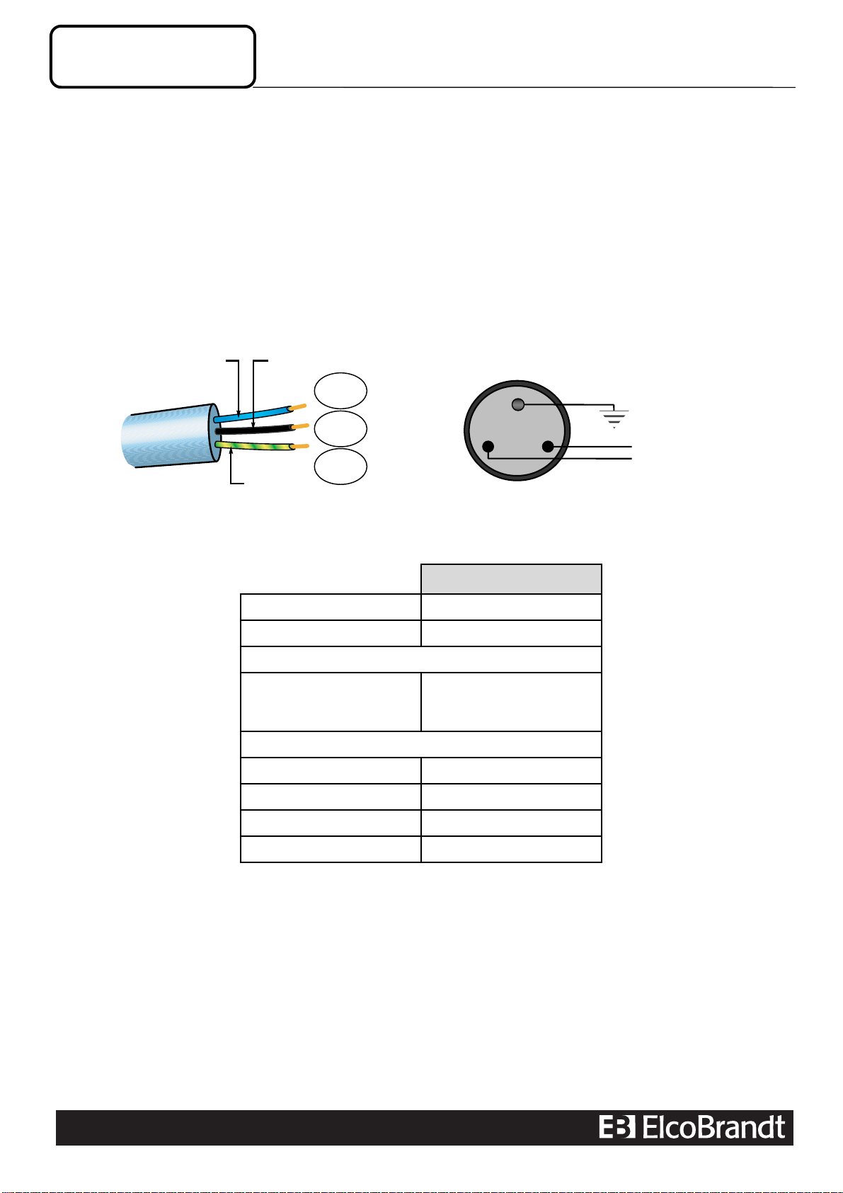
2.2. - Electrical connection
For a permanent connection, make sure an all-pole switch is placed into the supply line with a contact
distance of at least 3mm. The appliance must be placed in such a way as to leave the plug accessible
if it is flush-fitted.
Use of an earthed power socket, connected in compliance with current safety standards
The installation must be fitted with a 16 amp device for thermal protection.
Do not use the oven if the supply cord or its plug are damaged.
2.3. - Technical features
STEAM OVEN
Operating voltage 220-240V ~ 50 Hz
Total power 1,77 kW
Energy consumption
Heating to 100°C and
maintaining temperature
for 1 hour 0,71 kWh
Inside dimensions of oven
Width 38,5 cm
Height 18,2 cm
Depth 33,5 cm
Effective volume 23,5 litres
Earth
Live
(
L
)
Neutral (N)
Neutre
(N)
Phase
(L)
Terre
Fil vert/jaune
Fil bleu Fil noir, marron ou rouge
Blue Black, brown or red
Green and
Yellow
Neutral
(N)
Live
(L)
Earth

STEAM OVEN 2004 SOLO MODEL
Technical training
- 7 -
CU5-VAP2004-001UK-03/05
USING
3 - USING
3.1. - Setting the time
¾The first time the oven is turned on
•The display flashes on12.00
•Use the +and -buttons to adjust the time.
•Validate with SET (Validation is automatic after few seconds).
¾Changing the time
•Press on the + and - buttons simultaneously until the time starts to flash.
•Adjust the time using the + and - button.
•Validate with SET (Validation is automatic after few seconds).
3.2. - Possible functions
•Standard steam cooking: Temperature 100°C
•Defrosting : Temperature 60°C
•Independent timer: Accessible by the ‘SET’ button.
3.3. - Locking the control panel
The control panel can be locked. This can only be activated when you are not using timed or delayed
cooking features.
¾To lock
•Hold down the START/STOP button for a few seconds.
•A beep sounds and a “key” appears on the screen. From this moment, no button is live.
¾To unlock
•To unlock, hold down the START/STOP button for a few seconds. A beep sounds and the key
disappears.
3.4. - Cleaning the channel
Dismantle this channel by pulling upwards. Wipe it and replace it,
using the three notches provided for this purpose.

STEAM OVEN 2004 SOLO MODEL
Technical training
- 8 - CU5-VAP2004-001UK-03/05
PRINCIPLE
4 - GENERAL PRINCIPLE
The water contained in a removable tank is brought by an electrovalve on a heat generator where it is
transformed into steam. The steam obtained is maintained in the oven cavity by closing a flap.
This flap is bored several holes in order to avoid the pressurization of the cavity.
This cooking principle is different to a pressure-cooker where the obtained pressure is higher than the
atmospheric one.
Initially the oven will be saturated with steam and the temperature will be close to 100°C. In order to
avoid condensation, an electric blanket which covers the top will be supplied during all cooking time.
Tangential fan allows the constant cooling of the oven and the extraction of the steam when the flap
opens three minutes before the end of the cycle. A safety thermostat (210°C) protects the oven against
overheating. Two probes located in the cavity and in the generator allow the temperature control.
Steam generator Probe
Security thermostat
Electric blanket
Door switch
Thermal
activator Tangential fan
Tank
Probe
Valve
Power board

STEAM OVEN 2004 SOLO MODEL
Technical training
- 9 -
CU5-VAP2004-001UK-03/05
COOKING STEPS
5 - STUDY OF THE COOKING CYCLE
Cooking is divided into 5 steps.
¾Rise in the temperature and steam generation (Step 1)
Immediately after starting, the valve, the tangential fan, the heater, the electric blanket and the thermal
activator are supplied. The steam generation is important in order to quickly obtain saturation in the
cavity. The valve is supplied by step of 15 to 30 sec as soon as the generator temperature exceeds
130°C.
¾Upholding of the steam level (Step 2)
The heat generator is regulated by the probe. The thermal activator, the electric blanket and the
tangential fan are still supplied.
¾Steam emptying and temperature decreasing (Step 3)
Three minutes before the end, the thermal activator and the electrovalve are not supplied any more.
The flap opens, the tangential air flow involves the steam out of the cavity. The electric blanket is
always supplied.
¾Keep warm (Step 4)
This step takes place only if the door remains closed after the end of cooking. The tangential and the
electric blanket are always supplied. The maximum duration: 1 hour.
¾Cavity drying (Step 5)
This step starts as soon as the door is open or after 1 hour and continues during 3 minutes. The
tangential and the electric blanket are supplied.
STEAM OVEN 2004 SOLO MODEL
Technical training
- 10 - CU5-VAP2004-001UK-03/05
AIR FLOW
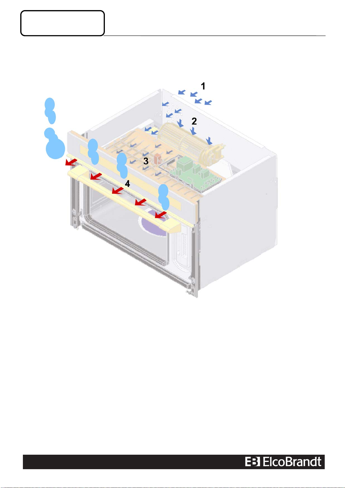
6 - AIR FLOW
STEAM OVEN 2004 SOLO MODEL
Technical training
- 11 -
CU5-VAP2004-001UK-03/05
COMPONENTS
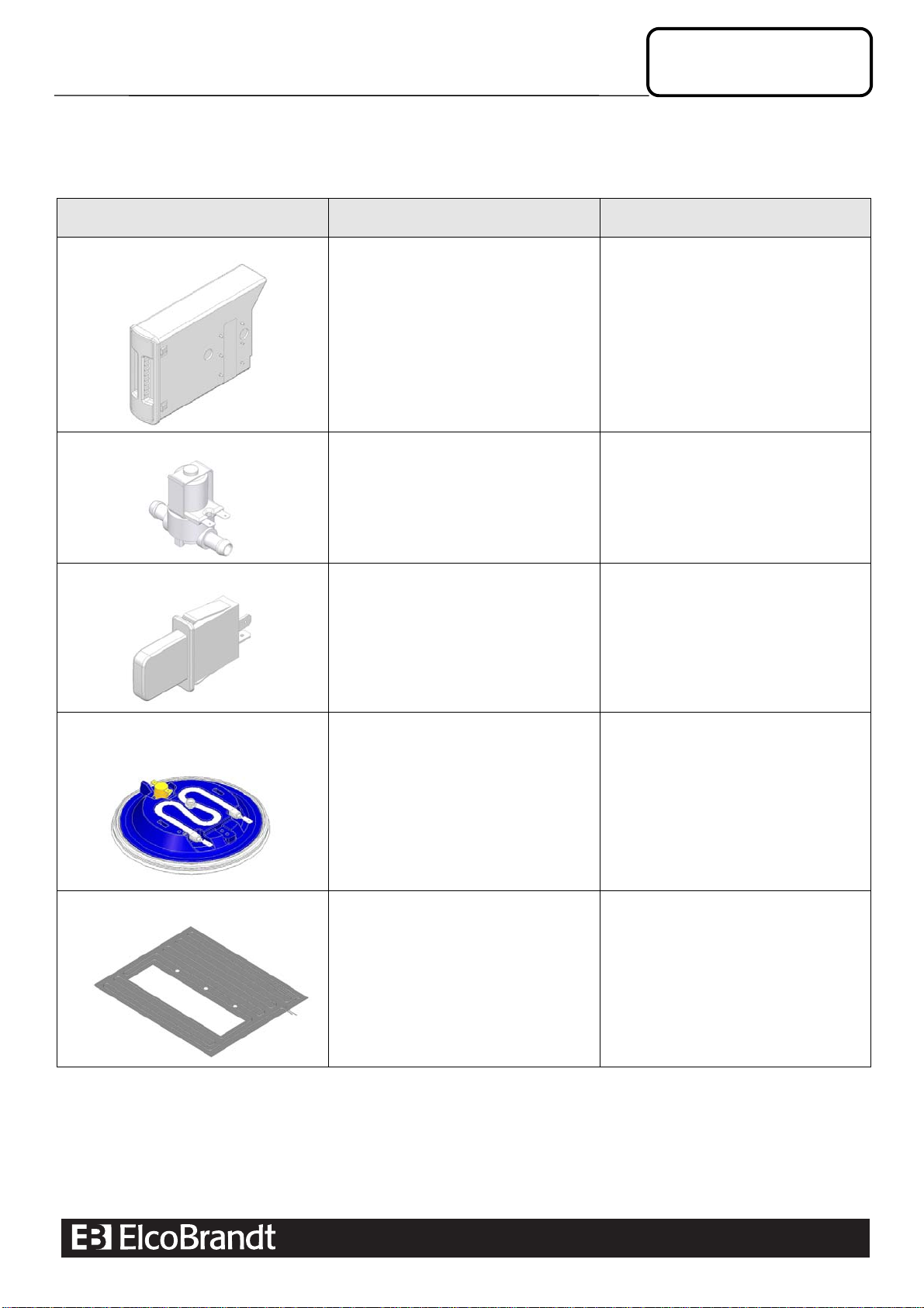
7 - DIFFERENT COMPONENTS
Designation Function Characteristics
Water tank The tank must be
•Full of water before each cooking.
•Emptied after each cooking
In case of too hard water, it’s better to
use a noncalcareous water.
The use of demineralized water is
disadvised.
•Capacity: 1 litre
Electrovalve The electrovalve supplies the
generator in water
•220/240V~
•2L/min
•3,7 kΩ
Door switch This switch allows to modify the cycle
when the door is open.
Door open= Switch is off
Door closed = switch is on
Heat generator
(upside down view)
The generator transforms water into
steam. It is made to receive back the
condensations at the time of cooking.
2 security thermostats (KX1 and KX2),
located underneath, protect against
overheating (T°C: 210°C).
•220/240V~
•1600 W
•35 Ω
Electric blanket During all cooking, the electric blanket is
supplied in order to avoid any risk of
condensation. It covers the top of the
cavity. Its temperature is close to 100°C.
It is protected by a thermal fuse.
•220/240V~
•350 Ω
•160 W
•Thermal fuse : 120°C

STEAM OVEN 2004 SOLO MODEL
Technical training
- 12 - CU5-VAP2004-001UK-03/05
COMPONENTS
Designation Function Characteristics
Double thermostat The double thermostat protects the oven
against overheating.
It’s located under the heat generator.
•220/240V~
•Opening T°C : 210°C
Thermal activator It maintains the flap closed during
cooking.
•220/240V~
•5 W
•1 KΩ
Tangential fan The tangential fan allows the constant
ventilation of the oven during all the cycle
and the extraction of the steam during the
last three minutes of the cycle.
•220/240V~
•10 W
•500 Ω
Cavity and generator probes
The probes measures
•The heat generator temperature
•The cavity temperature
They are recognized automatically by the
microprocessor. There is no possibility of
error in wiring.
N.T.C
•55KΩ at 20°C
•4,7KΩ at 90°C

STEAM OVEN 2004 SOLO MODEL
Technical training
- 13 -
CU5-VAP2004-001UK-03/05
DIAGNOSTIC
8 - DIAGRAM
STEAM OVEN 2004 SOLO MODEL
Technical training
- 14 - CU5-VAP2004-001UK-03/05
DIAGNOSTIC
9 - TEST PROGRAM
9.1. - Important instructions
•Connect (if possible) an ammeter to oven power supply.
•Entirely execute the test program.
•Record discrepancies noticed as the test program is running
•Next, check and replace if necessary the incriminated component(s).
•Perform right-operation check by executing the test program again.
9.2. - Preliminary steps
•Fill in the tank and put it in the right position
•Disconnect for 10 seconds minimum and connect again
•The time before entering the test mustn’t exceed 1 minute
•Press successively each key from left to right and maintain the right key during 3 seconds.
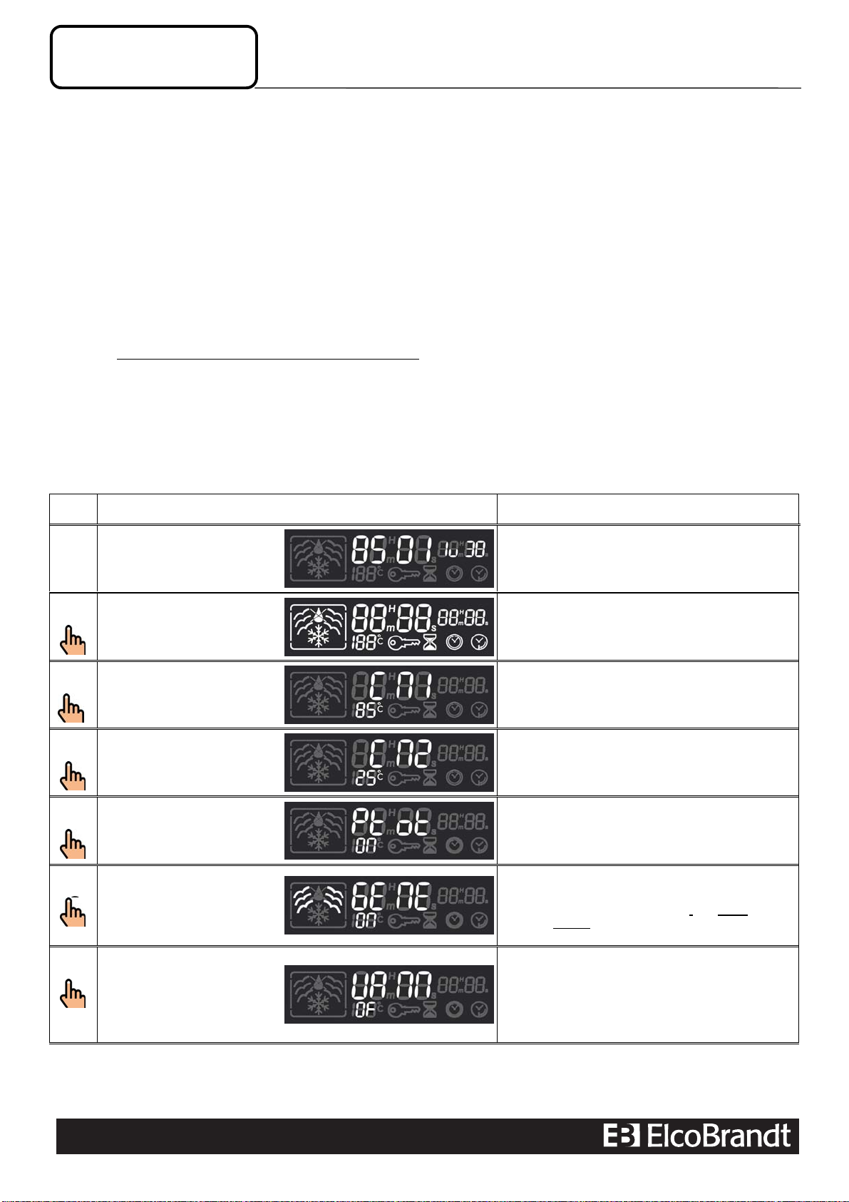
9.3. - Run of the test program
An action on the keys other than + and - or 3 min without action allows to quit the test program.
Step Run and display Remarks
1Start of the P.A.D. ⇒
•The test begins by indicative information on board
programming.
NO ⇒Do again the preliminary steps
Continue the test
2+Press once the +key ⇒
•All segments are lit.
NO ⇒Display board out of order.
Continue the test
3+Press once the +key ⇒
•NTC1 temperature in °C
Unusual value ⇒check the probe ‘55KΩat 20°C, 4,7kΩ
at 90°C’
Continue the test
4+Press once the +key ⇒
•NTC2 temperature in °C
Unusual value ⇒check the probe ‘55KΩat 20°C, 4,7kΩ
at 90°C’
Continue the test
5+Press once the +key ⇒
•All elements are supplied
Continue the test
6+Press once the +key ⇒
•The steam pictogram is flashing
•Heating element is supplied
I = 0 ⇒check the security thermostat, .the wiring and the
generator resistor. Lastly, change the power board
Continue the test
7+Press once the + key ⇒
•The valve has normally supplied the heating element
in water. If it’s not finished, the display is ‘VANN on’
VANN OF ⇒Open the door and check the water.
Take care : This opening is necessary to continue.
Continue the test

STEAM OVEN 2004 SOLO MODEL
Technical training
- 15 -
CU5-VAP2004-001UK-03/05
DIAGNOSTIC
Step Run and display Remarks
8+(After having opened
and closed again the
door ) Press once the +
key ⇒
•Tangential fan and heating cover are supplied. Open
the door to check the temperature of the cavity top. The
top must become very hot
•NO ⇒Check the wiring and the heating cover. The
ohmic value must be around : 350 Ω
Continue the test
9+Press once the +key ⇒
•‘Ver on’ is displayed and the thermal activator is
supplied. : The flap is closing slowly
NO ⇒Check the supply of the activator and its resistance
(1kΩ)
Continue the test
10 +Press once the +key ⇒End of the test

Brandt Customer Services
B.P. 69526 - 95060 Cergy-Pontoise cedex
SAS au capital de 2.500.00 € - RCS Pontoise B 440 303 303 - SIRET 440 303 303 00026 - APE 514F
Service formation : Agrément N° 11 95 00 685 95 - Fax : 33 (0)1 34 30 68 42 - E-mail : for[email protected]
©
Brandt Customer Services - Formation : CU5 – VAP2004- 001UK - 03/05
destinée aux : hôtesses d'accueil .chargés de clientèle
.gestionnaires de pièces détachées .responsables
techniques .techniciens .livreurs installateurs .formateurs
Table of contents
Popular Oven manuals by other brands

Alto-Shaam
Alto-Shaam COMBITHERM CTC Series Operation, Maintenance, Troubleshooting, Wiring Diagrams

Kenmore
Kenmore 911.41389 owner's manual

NEFF
NEFF B6ACM7AG0A User manual and installation instructions

Beko
Beko GEBM19300DXMPF user manual

Oster
Oster TSSTTVCG02 Quick tips

Whirlpool
Whirlpool RB760PXT Use & care guide


