Elcon E-TRIP Instruction Manual

Version: 2004/08/16 Order No.: 9526 © ELCON Systemtechnik GmbH http://www.elcon-system.de
E
E-
-T
TR
RI
IP
P
®
®
Onboard Computer
for Fleet Management
Mounting Guidelines

Scope of supply
E-TRIP ®Version: 2004/08/16 Order No.: 9526 Page 2
1) E-TRIP Onboard Unit
2) E-TRIP Operating Manual
3) Cable set
4) Built-in frame
5) Clamps
6) PSRR antenna
7) GPS antenna
8) GSM antenna
9) Driver card

TABLE OF CONTENTS
E-TRIP ®Version: 2004/08/16 Order No.: 9526 Page 3
1INTRODUCTION............................................4
1.1 System architecture and components.............4
1.2 Functions........................................................5
2STATEMENTS...............................................6
3INSTALLATION .............................................7
3.1 Antennas........................................................7
3.2 Maintenance...................................................8
3.3 Connection of the device ................................9
3.4 Description of signals ...................................10
3.4.1 SAE J1708 Interface.....................................11
3.4.2 Digital Input ..................................................11
3.4.3 Digital Output................................................12
3.4.4 Temperature sensor .....................................13
3.4.5 NMEA interface ............................................13
3.4.6 Auxiliary Serial Port ......................................13
3.5 Installation of the Onboard Unit ....................14
3.6 SIM card installation .....................................17
3.7 Installation of Orbcomm modem (Option) .....18
3.7.1 LED Codes of Stella ST 2500.......................19
3.8 Configuration of the Onboard Unit................20
3.8.1 Setting of date and time................................20
3.8.2 Setting of time zone......................................20
3.8.3 Check GPS function .....................................20
4AGENCY INFORMATION............................21
5DEALERS ....................................................22

1. INTRODUCTION
E-TRIP ®Version: 2004/08/16 Order No.: 9526 Page 4
1 INTRODUCTION
E-TRIP®is a high-performance onboard computer for
motor vehicles such as trucks, buses or cars. Having
the size of a car radio, the onboard unit collects
vehicle operation data, driver and environmental data
and transfers them to the fleet via GSM (Global
System for Mobile Communications, SMS - Short
Message Service). It supports all administration tasks
occurring in a modern fleet and is a basic part of a
digital fleet management system.
E-TRIP®may also serve for toll collection or work as
accident data recorder. The unit is able to display limit
and threshold values as well as indicate alarm
conditions.
E-TRIP®is a manipulation-safe unit. You are able to
analyze the fuel economy of your vehicle's fleet while
the driver can check the vehicle's operating data.
E-TRIP®has been designed as a modular unit. You
can configure the unit according to your individual
requirements.
1.1 System architecture and components
E-TRIP®comprises the following components:
• LCD (Liquid Crystal Display)
• Operation keys
• Signal generator
• LED´s
• GPS module
for the exact location and tracing of vehicles, RSE
(Road Side Equipment) is not required
• GSM (Global System for Mobile Communications)
module for the data transfer through the mobile
telephone network
• PSRR module
• OrbComm module (option)
• E-TRIP Service Tool – the E-TRIP®configuration
program that runs under MS Windows®on your PC
• System cards - one system card for the company -
supplied by your service center
• Driver cards - one driver card for each driver

1. INTRODUCTION
E-TRIP ®Version: 2004/08/16 Order No.: 9526 Page 5
1.2 Functions
Using the full range E-TRIP®allows you to:
• log to vehicle data, tracking data and
environmental data securely,
• store these data securely,
• transfer these data automatically and securely,
• display data "driver-friendly", i.e. clearly and easily
legible,
• check data, and
• control engine, fuel consumption and efficiency.
LCD (Liquid Crystal Display): two lines, each of 16
characters length, for digital readouts, menu functions
and submenus, messages
Operation keys: for manual inputs, menu control,
operations.
Acoustic signals: to confirm correct operation
actions or signal errors.
RTC (Real-Time Clock): battery-backed, For the
correct time information. Switches between standard
time and daylight saving time.
GPS receiver: Use of the GPS (Global Positioning
System) satellite signals for vehicle's positioning,
either upon request or at adjustable intervals.
PSRR: (Private Short Range Radio). The automatic
data transfer between the onboard unit and the
dispatcher can be realized in a short range
(approximately 150 ft.).
Serial external interface: allows the connection of a
temperature sensor, for example in the loading space of
the vehicle.
SAEJ1708 interface: collection of vehicle data
Acceleration and gyro sensors for three axles are
important if you would like to use E-TRIP®as accident
data recorder (future implementation).
Digital input 0/12 V: storage and recall of the brake
block erosion by using the brake pedal
ARO (Auxiliary Relay Output): Customized relay
function to switch a relay via GSM (see signal: ARO_A
and ARO_B in chapter 3.4).
It is not allowed to control the motor
management via this function!
Smart card reader: for bringing into service, driver
identification, programming, service application

STATEMENTS
E-TRIP ®Version: 2004/08/16 Order No.: 9526 Page 6
2 STATEMENTS
1. Statement according to FCC part 15.19:
This device complies with Part 15 of the FCC
Rules. Operation is subject to the following two
conditions: (1) this device may not cause harmful
interference, and (2) this device must accept any
interference received, including interference that
may cause undesired operation.
2. Statement according to FCC part 15.21:
Modifications not expressly approved by this
company could void the user's authority to
operate the equipment.
3. Statement according to FCC part 15.105:
NOTE: This equipment has been tested and
found to comply with the limits for a Class B
digital device, pursuant to Part 15 of the FCC
Rules. These limits are designed to provide
reasonable protection against harmful
interference in a residential installation. This
equipment generates, uses and can radiate radio
frequency energy and, if not installed and used in
accordance with the instructions, may cause
harmful interference to radio communications.
However, there is no guarantee that interference
will not occur in a particular installation. If this
equipment does cause harmful interference to
radio or television reception, which can be
determined by turning the equipment off and on, the
user is encouraged to try to correct the interference
by one or more of the following measures:
Reorient or relocate the receiving antenna.
Increase the separation between the equip-ment
and receiver.
Connect the equipment into an outlet on a circuit
different from that to which the receiver is
connected.
Consult the dealer or an experienced radio/TV
technician for help.
4. RF Exposure mobile:
The external antennas used for this mobile
transmitter must provide a separation distance of at
least 20 cm from all persons and must not be co-
located or operating in conjunction with any other
antenna or transmitter.
5. Statement according to road safety:
The use of the function ARO (Auxiliary Relay
Output) of the E-TRIP®is not permissible in the
member countries of the Economic Commission for
Europe (ECE) to control the engine. It is not
permitted, with the help of relay functions, to
influence the control of engine management or to
influence other functions affecting vehicle or road
safety, in vehicles participating in public transport.

INSTALLATION
E-TRIP ®Version: 2004/08/16 Order No.: 9526 Page 7
3 INSTALLATION
E-TRIP®has to be installed by service personnel of a special workshop only. The correct connection and first software
installation as well as configuration are reserved to specialists and mandatory for the proper and fault-free function of the
unit.
The location of installation is optional and can be chosen according to your individual requirements.
Please ask your dealer for more information.
The detailed description of the installation is given in a separate document. This document is available from your vendor or
service partner.
3.1 Antennas
For the installation of the antennas for E-TRIP only the following two antennas are permissible:
1) AEB 2400 for PSRR (DECT)
Technical Data:
Frequencies: 2.1/2.8 GHz UMTS-BLUETOOTH
Impedance: 50 Ohms
Gain: 2.65 dBi
2) MCA 18 90 STRIPE for GSM
Technical Data:
Frequency range: AMPS: 824 - 894 MHz
GSM 900: 880 - 960 MHz
GSM 1800: 1710 - 1880 MHz
GSM 1900: 1850 – 1990 MHz
Impedance: 50 Ohms
Gain: 2.1 dBi

INSTALLATION
E-TRIP ®Version: 2004/08/16 Order No.: 9526 Page 8
3.2 Maintenance
To clean the unit's front panel, use a clean cloth only. It should be soft, dust-laying and antistatic. Don't apply any cleaning
agents, in order to prevent the surface from being damaged. Special cleaning measures or procedures are not required.

INSTALLATION
E-TRIP ®Version: 2004/08/16 Order No.: 9526 Page 9
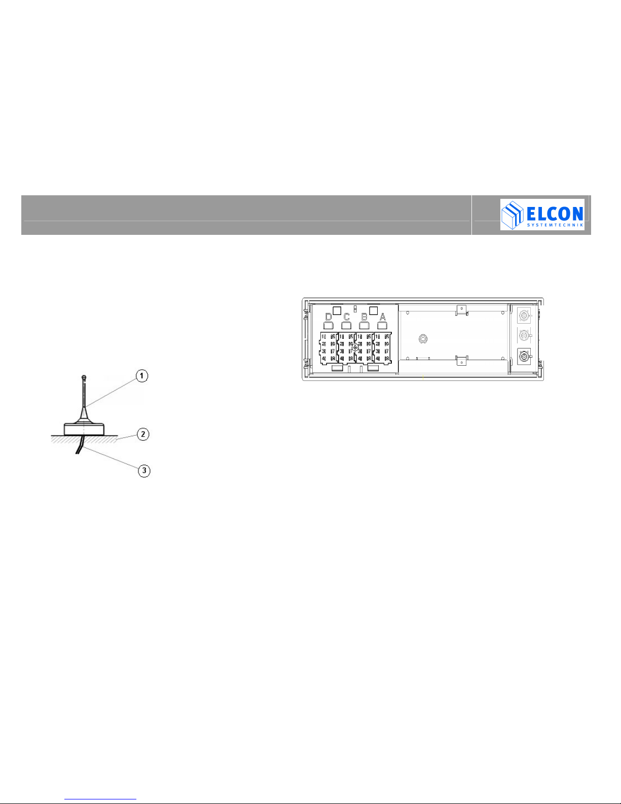
3.3 Connection of the device
Chamber D Chamber C Chamber B Chamber A
D1
TEMP_Sens_A C1
DIGI_IN_1 B1 Speed Pulse A1
Battery +
D2
TEMP_Sens_B C2
DIGI_IN_2 B2 - A2
Light
D3
NMEA_TxD C3
DIGI_IN_3 B3 - A3
Ignition
D4
GND C4
DIGI_IN_4 B4 RPM A4
-
D5
AUX_SER_TxD C5
ALARM_A B5 - A5
GND
D6
AUX_SER_RxD C6
ALARM_B B6 SAE_J1708_A A6
(GND)
D7
AUX_SER_DSR C7
ARO_A B7 SAE_J1708_GND A7
-
D8
AUX_SER_DTR C8
ARO_B B8 SAE_J1708_B A8
-

INSTALLATION
E-TRIP ®Version: 2004/08/16 Order No.: 9526 Page 10
3.4 Description of signals
Chamber A:
A1 Battery+ : Vehicle on-board supply system
+9V ...+36V
A2 Light: for switching on the OBU through
the vehicle light.
A3 Ignition: for switching on the OBU through
the ignition.
A5 GND: Vehicle on-board supply system:
ground
Chamber B:
B1 Speed Pulse: Available speed signal in sine-
shaped or rectangular form.
VL max. = 3.0V
VH min. = 4.5V (tolerant up to 40V)
NOTE: If the speed is metered via input B1, then input
B4 shall be connected with a respective RPM
sensor or connected to ground.
B4 RPM Alternatively to bus J1708, the
OBU can meter the engine speed
also via the pulse output of the
RPM sensor.
B6 SAE_J1708_A: SAE J1708 Interface, Line A
B7 SAE_J1708_GND: SAE J1708 Interface, GND
B8 SAE_J1708_B: SAE J1708 Interface, Line B
B6 – B8: see subchapter 3.4.1
Chamber C:
C1 DIGI_IN_1: Input: +9V ... +36V DC
C1 – C4: see subchapter 3.4.2
C2 DIGI_IN_2: Input: +9V ... +36V DC
C3 DIGI_IN_3: Input: +9V ... +36V DC
C4 DIGI_IN_4: Input: +9V ... +36V DC
C5 ALARM_A: Relais output
C6 ALARM_B: C5 – C6: see subchapter 3.4.3
C7 ARO_A: Auxiliary Relay Output
C8 ARO_B: C7 – C8: see subchapter 3.4.3.2
Chamber D:
D1 TEMP_Sens_A: Input of temperature sensor
D2 TEMP_Sens_B: D1 – D2: see subchapter 3.4.4
D3 NMEA_TxD: RS232 - port for connection of external
navigation devices with NMEA input;
see subchapter 3.4.5
D4 GND: Ground NMEA output resp.
PIN 5 D-SUB9 ORBCOMM
D5 Aux_Ser_TxD: PIN 3 D-SUB9 ORBCOMM
D6 Aux_Ser_RxD: PIN 2 D-SUB9 ORBCOMM
D7 Aux_Ser_DSR: PIN 6 D-SUB9 ORBCOMM
D8 Aux_Ser_DTR: PIN 4 D-SUB9 ORBCOMM
D4 – D8: see subchapter 3.4.6

INSTALLATION
E-TRIP ®Version: 2004/08/16 Order No.: 9526 Page 11
3.4.1 SAE J1708 Interface
The onboard unit can record the following
information via the vehicle interface SAE J1708:
1) Speed
2) Engine speed
3) Fuel consumption
4) PTO
5) Brake Indicator
6) Reverse gear
The speed can be recorded through J1708 or a
speed pulse input. The Onboard Unit also registers
the engine speed and PTO status. With help of the
PC program E-TRIP Service Tool it is possible to
determine which input of the Onboard Unit shall be
used.
3.4.2 Digital Input
The digital inputs allow to have below functions recorded by
the Onboard computer:
1) PTO
2) Direction indicator {Turn Indicator}
3) Brake indicator {Brake Indicator}
4) AUX 1 Input
This input offers to collect and record any digital
information delivered by the Onboard Unit.
5) AUX 2 Input
like with 4)
The inputs C1 ... C4 can be configured with help of the PC
program E-TRIP Service Tool. For further information on this
topic please refer to the Service Tool Manual.

INSTALLATION
E-TRIP ®Version: 2004/08/16 Order No.: 9526 Page 12
3.4.3 Digital Output
3.4.3.1 ALARM interface
If the external temperature sensor indicates that the
real temperature has exceeded the programmed
temperature limit or fallen below a minimum value,
the ALARM output will be activated and displayed as
alarm message.
Upon wiring of output C6, C7, the following limits
must not be exceeded.
Relais Rating:
- Nominal switching capacity: 2A 30V DC
- Max. switching power: 60W
- Max. switching voltage: 220 V DC
3.4.3.2 ARO interface
The ARO (Auxiliary Relay Output) serves for
triggering a vehicle relay which control any
customized function. To use this function, it is
necessary to enter a PIN upon setting the specific
vehicle data set under E-TRIP Master.
Recommendation to the workshop personnel:
The workshop card offers to select from the onboard unit menu
the function ARO relay. It allows to enable resp. disable the
ARO function.
Menu -> Services -> System -> Aux.RelayOutput
If the ARO function is disabled, the Onboard Unit switches
through the ARO if a High signal is applied to the input of
clamp A3.
In case the ARO function is initiated by the Office, the
Onboard Unit activates the function after the engine has
been switched off. For this, it is relevant that the engine
speed input is adequately switched.
The ARO represents a galvanically separated contact.
Upon wiring of output C7, C8, the following limits must not be
exceeded.
Relais Rating:
- Nominal switching capacity: 2A 30V DC
- Max. switching power: 60W
- Max. switching voltage: 220 V DC

INSTALLATION
E-TRIP ®Version: 2004/08/16 Order No.: 9526 Page 13
3.4.4 Temperature sensor
The clip contacts D1 and D2 permit connection of an
external temperature sensor that can be acquired
from your supplier under order no. 9514. After
installation of the hardware and activation through
the PC program E-TRIP Service Tool, the
temperature value can be indicated by the Onboard
Unit. The activation is carried out with help of Cargo
Temperature on the register card HW Settings.
3.4.5 NMEA interface
The control of peripheral PC equipment (laptops,
PDAs, etc.) by using navigation software can be
executed via output D3/D4 of the Onboard Unit in a
way that the current vehicle position is transmitted
via this interface. In addition to the output D3/D4, the
vehicle position is also sent out via the service
interface on the front panel of the Onboard Unit. The
vehicle position data can be sent only then if below
smart cards: System Card and Workshop Card are
not inserted und the E-TRIP Service Tool is not
linked with the Onboard Unit.
The following NMEA 0183 records will be sent to the
navigation software:
1) $GPGGA
2) $GPVTG
3) $GPRMC
3.4.6 Auxiliary Serial Port
The „Auxiliary Serial Port“ represents a serial interface
(RS232) with two control wires DSR and DTR. This interface
allows, i.a., connection of an ORBCOMM module. For this,
please use the cable set provided as part of the OrbComm
supply package.
INSTALLATION
E-TRIP ®Version: 2004/08/16 Order No.: 9526 Page 14
3.5 Installation of the Onboard Unit
Safety precautions :
Upon device installation make sure to keep a
minimum distance of 20 cm between the radio
antenna(e) and the workplace.
Any application of the device other than for its
contractual use may cause not only property
damage. Therefore always make sure to apply
our product only for the intended use !
During installation and connection please observe the
following safety precautions:
• Disconnect negative pole of the battery!
Observe the safety instructions from the respective car
manufacturer. Note that, upon disconnecting, devices with
volatile memory will lose their information. Therefore it is
necessary, before disconnection, to write down all relevant
data and to notify the car owner that there may be need for
reprogramming.
• When drilling holes, make sure not to damage any car parts
or electric wires.
• The cross section of both positive and negative cable must
not be less than 0.5 mm².
• Improper installation may cause interferences with the
Onboard Unit and other electronic systems of the vehicle.
• E-TRIP shall be connected to the in-car outlets as
recommended by the car manufacturer only through the
cable set provided as part of the supply.

INSTALLATION
E-TRIP ®Version: 2004/08/16 Order No.: 9526 Page 15
Installation in the car dashboard and other
mounting slots provided:
1. Remove holding frame ( figure 1 ) after having
unlocked the arresters.
Insert the two clamps ( figure 2 ) until stop into
the designated holes in the faceplate. Then
remove holding frame.
Holding frame Clamps
figure 1
figure 2
2. Install holding frame in the dashboard.
Note :
Before installation of the holding frame, pull cable trunks
through the holding frame!
After proper installation of the holding frame in the
dashboard, turn the respective latches to lock the holding
frame safely in its place (see figure 3).
figure 3
3. Now establish the required electrical connections to the
car outlets as recommended by the car manufacturer.
Before connection :
Please check carefully the wiring inside your vehicle.
Improper wiring may cause not only damage to the
device, but also cable fires or battery explosions.
INSTALLATION
E-TRIP ®Version: 2004/08/16 Order No.: 9526 Page 16
4. Choose an appropriate position for the GPS /
GSM antenna. Make sure to direct the GPS
antenna towards the sky, i.e. it must have free
sight to the sky.
Make the fastening holes and the cable
grommets for the GPS / GSM antenna.
The bending radius of the cables must not
be less than 1 cm. Pay attention to above
safety precautions!
(1) GPS-/GSM-
antenna
(2) Car roof
(3) GPS /GSM
cable
Connect the antenna cables (blue for GPS, violet for
GSM, fawn for PSRR), until they noticeably snap in.
Connect the cable trunks with the four plugs of
different colours to the device, until they noticeably
snap in.
( A-white, B-yellow, C-red, D-brown ). Note the proper fitting as
shown in figure 4.
figure 4
5. Carefully push the device into the holding frame until it
noticeably locks in place. With this, the cables must not
be jammed nor crimped!
6. Note :
In case your vehicle is not equipped with the special
terminal clamps for connection, it shall be respectively
retrofitted by an authorized car workshop, or by the
Technical service (see Agency Information, Page 21).
GPS
GSM
PSRR
INSTALLATION
E-TRIP ®Version: 2004/08/16 Order No.: 9526 Page 17
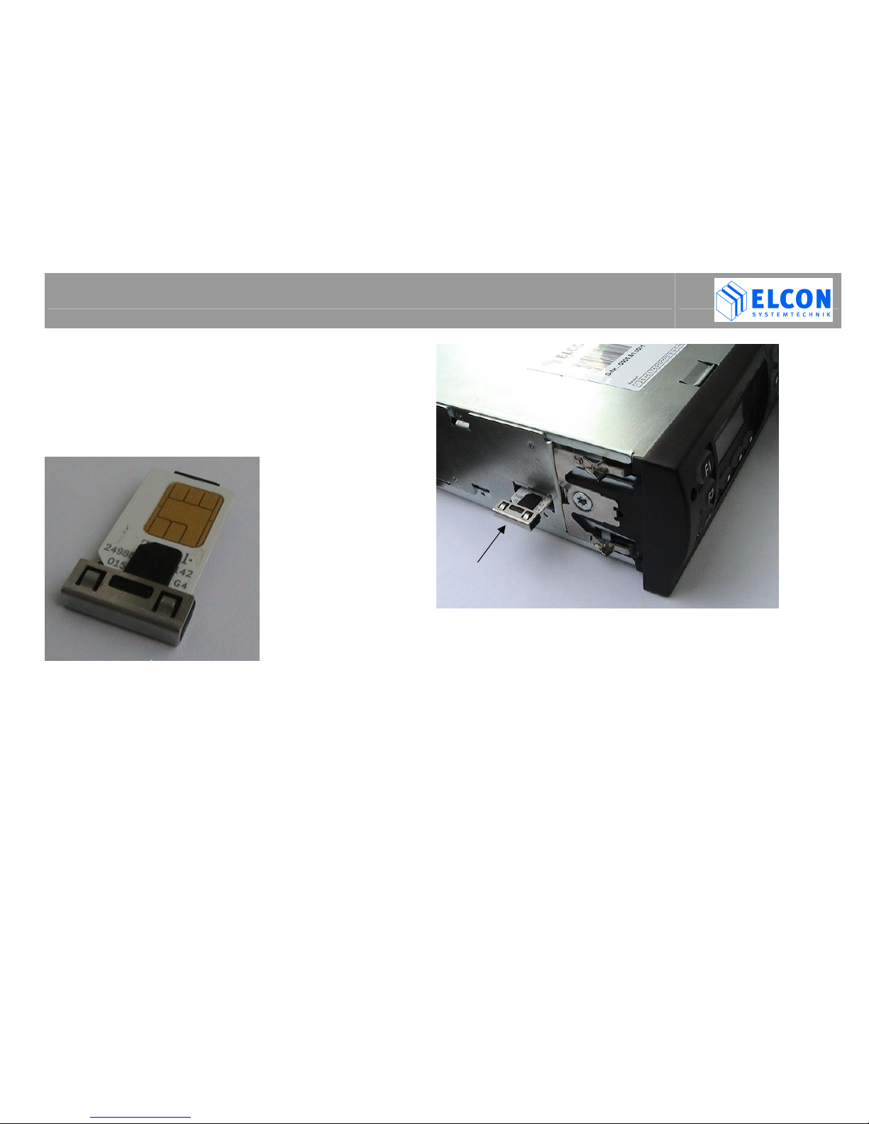
3.6 SIM card installation
Make sure you have got a plug-in SIM card.
Insert the SIM card into the provided SIM card
holder, see figure 5 .
figure 5
After this, insert the SIM card holder into the
Onboard Unit as shown in figure 6, until the card
holder snaps in. Make sure that the chip points to the
top (cf. also figure 5).
figure 6
INSTALLATION
E-TRIP ®Version: 2004/08/16 Order No.: 9526 Page 18
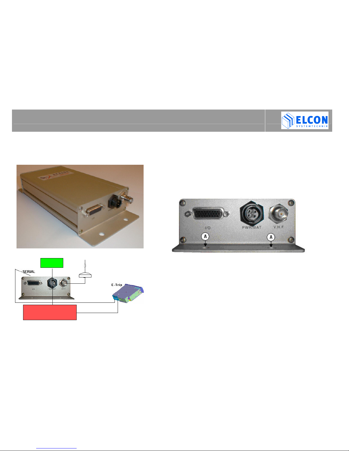
3.7 Installation of Orbcomm modem
(Option)
Modul type: ST 2500 Data Communicator
1. Please choose an appropriate mounting position for the
modem und the battery in the vehicle. Make sure that
modem and the related battery are situated not too far from
each other.
2. Fasten the modem by means of screws at the four
designated fixing points; see (A) figure 7. After this, fasten
the battery with the provided holding angle.
figure 7
3. When laying the cables, take care not to jam or cut-off the
cable by moving parts such as seat rails, doors etc.
4. Fix the antenna in a suitable position on the vehicle roof
and lay the cable in such a way that it will not be damaged.
The bending radius of the antenna cable must not be less
than 1 cm.
5. Link the Onboard Unit and the ORBCOMM Modem through
chamber D with the modem´s 9-pole connection socket
(SERIAL).
Battery
.
On-board voltage
Antenna

INSTALLATION
E-TRIP ®Version: 2004/08/16 Order No.: 9526 Page 19
figure 8
6. Finally, connect the cable set to the outlets
recommended by the car manufacturer ( +V and
– Ground ). After this, link the circular connector
of the Orbcomm Modems (figure 7, PWR/BAT)
and the battery with the modem.
3.7.1LED Codes of Stella ST 2500
L1 LED:
• While the unit is searching the satellite downlink, L1
flashes in red.
• Once a downlink is captured, the LED turns green.
• Green flash signals indicate that a transmission
attempt has been made.
L2 LED:
• This LED shines in yellow when the original buffer
contains a message

INSTALLATION
E-TRIP ®Version: 2004/08/16 Order No.: 9526 Page 20
3.8 Configuration of the Onboard Unit
After installation of the Onboard Unit, it has to be
configured for the specific vehicle via the provided
service interface cable. For detailed configuration
description please refer to the the PC program
manual E-TRIP ServiceTool.
3.8.1 Setting of date and time
The configuration procedure shall be completed by
setting the RTC (Real Time Clock ) that forms
integral part of the Onboard Unit. For this, insert your
workshop card into the Onboard Unit and press
button M / OK, to enter the menu. Via the cursor
keys you can now select the following menu items:
Menu -> Services -> Date/Time -> Adjustment
which shall be respectively acknowledged by
pressing the button M / OK.
After selecting the function (Adjustment) for setting
the RTC, at first you shall enter the time.
When doing so, pay attention not to enter the
local time, but GMT (Greenwich Mean Time).
Use the cursor keys to set the correct time.
Acknowledge your input via button M / OK. Then you
may enter the date the same way.
3.8.2 Setting of time zone
After selection of the menu items:
Menu -> Services -> Date/Time -> Time zone
you can enter the value of the local time zone. After this, check
the local time by leaving the menu (via button C), to display a
driver information that would show time and date in the upper
line.
3.8.3 Check GPS function
Insert the workshop card into the Onboard Unit and select the
driver information „GPS Data“ via cursor keys
and
.Wait
until „GPS: no signal“ disappears from the display. When
putting the device into service for the very first time, this may
take up to 10 minutes.
Table of contents
Popular Automobile Accessories manuals by other brands


Aukey
Aukey CC-A3 user manual

Beeper
Beeper REC110X-N User& installer's manual

Kuda-Phonebase
Kuda-Phonebase 043350 Installation instruction

Lippert Components
Lippert Components COACH STEP Installation, operation and service manual

QA1
QA1 MU1RCA Install instructions

VDO
VDO VIEWLINE PRESSURE GAUGES Product information