manuals.online logo
Brands
  1. Home
  2. •
  3. Brands
  4. •
  5. Fortin
  6. •
  7. Automobile Accessories
  8. •
  9. Fortin EVO-GMT1 User manual

Fortin EVO-GMT1 User manual

WITH EVO-ALL INSTALLATION
GUIDE FOR T-HARNESS FOR GENERAL MOTORS VEHICLE
EVO-GMT1
COMBO EVO-ALL &THAR-GM1 v2
2010-2015
Equinox
2011-2015
Cruze
2010-2015
GMC
Terrain
2010-2015
BUICK
LaCrosse
2011-2014
Regal
2010-2015
Camaro
VEHICLE FIT GUIDE
2012-2014
Orlando
2012-2014
Sonic
2013-2015
Encore
2013-2014
Verano
2013-2014
Malibu
2013-2015
Trax
CHEVROLET
*OEM remote not functional while the vehicle is started.
GMC
BUICK
CHEVROLET
HARDWARE VERSION
Date: xx-xx
HARDWARE VERSION : 3
FIRMWAREVERSION : 4.0+
Service No : 000 102 04 2536
INTERFACE MODULE
Madein Canada
PATENTSPENDING US: 2007-228827-A1
EVO 6
FIRMWARE VERSION
Minimum 4.18REQUIRED
FIRMWARE VERSION
[ ]
Minimum
0070.
GM
OR
OEM Remote
Monitoring*
PARTS INCLUDED
THAR-GM1 v2
+THAR-GM1v2
2015
Colorado
Page 2
EVO-CHR T1 (THAR-CHR1) EVO-GMT1
PREPARATION
Gently pull up the top of the
steering column between the
steering wheel and the dash.
Stop when you feel resistence.
Right of Steering Column
Left of Steering Column
INSTALLATION PROCEDURE
2
Under the Steering Column
Unscrew.
Unscrew.
Unscrew. 3
4
1
Connect to vehicle
Connect to Remote-Starter/Alarm
Connection not required with Data-link
Input Output | Sortie
WIRE LEGEND
Connection always required
LEGENDE
WITH DATA-LINK
In order to utilize this type of connection the
remote starter or alarm system must be
compatible with the Fortin Data-link
protocol.
For all other remote-starters or
alarm-systems.
WITH OUT DATA-LINK
Go Page 4
Go Page 3
STAND ALONE
Go Page 5
EVO-ALL PROGRAMMING
PROCEDURE Go Page 6
A B C
A remote car starter installation can
be completed using only the
interface module. An after-market
remote car starter not required.
Automatic transmission only
Page 3
Ignition
Accessory
STARTER
EVO-ALL
Back view Ignition Connector
1 2 3 4 5 6 7 8
9 10 11 12 13 14 15 16
1
Pin-1 Green | vert
CAN SW
n.c.
n.c.
Brown
n.c.
n.c.
6 PIN RED CONN.
EVO-ALL
5 PIN CONN.
EVO-ALL
Data-Link Port
Data-Link
4 PIN CONN.
EVO-ALL Data-Link
4 PIN CONN.
Ignition barrel
INSTALLATION WITH DATA-LINK
For installation without DATA-LINK use next page
Brown
Yellow
20 PIN CONN.
EVO-ALL
Parking Lights (-) Parking Lights
Lt. Blue
Cruze : Green/Grey Sonic : Lt.Green
At Parking Light switch
Parking Light switch
Key Bypass
IMMO connector
Back view
Connector Burgundy
OBD-II
Front view
Connector
Lower left of the dash
Do not use
Parking Lights(+)
12V
Red
CONNECTION
A
Page 4
Do not use Parking Lights
from the remote starter
(+)
Ignition barrel
Parking Light switch
EVO-ALL
Dk. Blue
Green
Purple/White
Purple
Door Status
Unlock/Disarm
Lock/Arm
(-) While Running
Brown/White
Tachometer Pink
Black
White Trunk Status
Pink/BlackHood Status
Hand Brake
Foot Brake
Yellow/BlackTrunk Release
Back view Ignition Connector
Key Bypass
IMMO connector
Back view
Connector Burgundy
Orange Heated Seats
1 2 3 4 5 6 7 8
9 10 11 12 13 14 15 16
1
CAN SW
n.c.
n.c.
Brown
n.c.
n.c.
OBD-II
Front view
Connector
Lower left of the dash
6 PIN RED CONN.
EVO-ALL
20 PIN CONN.
EVO-ALL
5 PIN CONN.
EVO-ALL
Data-Link
4 PIN CONN.
EVO-ALL
Purple/Yellow(+) Start
(+) 12VBattery
Ground
Red
Black
Blue
White
n.c.
n.c.
INSTALLATION WITHOUT DATA-LINK
For installation with DATA-LINK use previews page
Ignition
Accessory
STARTER
Start
Ground
12V
Brown
Yellow
Data-Link
4 PIN CONN.
Parking Lights
(-) Parking Lights
Lt. Blue - Cruze : Green/Grey
Sonic : Lt.Green
At Parking Light switch
Cut off the plug of the 4 Pin
Data-Link connector
Pin-1 Green | vert
EVO-CHR T1 (THAR-CHR1) EVO-GMT1
CONNECTION
B
Page 5
B
Orange/Black
Orange
Green
Purple/White
Purple
Yellow
White
Red/Blue
Lt. Blue/Black
Green/White
Purple/Yellow
Pink/Black
Pink
Black
Green/Red
White/Black
Lt. Blue
IN
IN
IN
OUT
OUT
IN
IN
IN
IN
OUT
OUT
IN
OUT
OUT
IN
A
A11
A12
A13
A14
A15
A16
A17
A18
A19
A20
A1
A2
A3
A4
A5
A6
A7
A8
A9
A10
THAR-GM1V2
6 PIN RED
CONN.
5 PIN
CONN.
EVO-ALL
Data-Link
4 PIN CONN.
STAND ALONE INSTALLATION
TOVEHICLE PARKING LIGHT
START / STOP EXTERNAL CONTROL
(-) External Input
(-) Parking Light OUT
Dk. Blue
Brown/White
Yellow/Black
Safety override switch
commutateur de sécurité
Hood Pin
Hood Pin
EVO-ALL
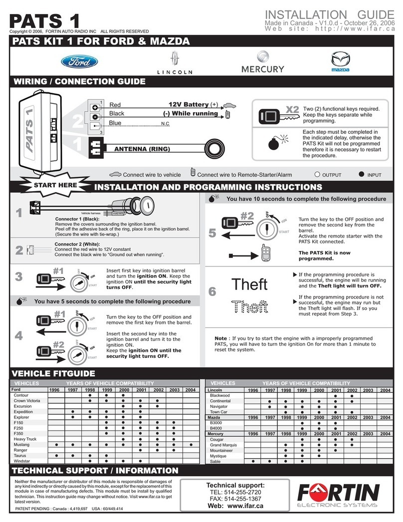
Configure the EVO-ALL as a Stand Alone Remote Starter: Connect the module to the
FlashLink Updater 2 (sold separately) and use the FlashLink Updater software to enable
option D1 in options menu.
Press the OEM remote’s Lock button 3x to remote-start (or remote-stop) the vehicle.
D1
Data-Link 4 PIN CONN.
Not connected
Pas branché
LOCK
3X
Back view Ignition Connector
Ignition barrel
Key Bypass
IMMO connector
Back view
Connector
Burgundy
1 2 3 4 5 6 7 8
9 10 11 12 13 14 15 16
1
CAN SW
n.c.
n.c.
Brown
n.c.
n.c.
OBD-II
Front view
Connector
Lower left of the dash
Pin-1
Green | Vert
AUTOMATIC TRANSMISSION ONLY
CONNECTION
C
NOTE:
OEM remote not functional while the vehicle is started.
Page 6
EVO-CHR T1 (THAR-CHR1) EVO-GMT1
The YELLOW LED
will turn back ON.
The Blue LED will
flash rapidly. CAN
data programmed.
The module is
now
programmed.
LOCK
ACCON
PUSH
START
OFF
Turn the Ignition
OFF.
All LED's
turn OFF.
Turn the Ignition to
the ON/RUN
position.
Wait until the RED
LED flashes once
(1x) and then turns
back ON.
Remove the key
from the ignition
switch.
Reinsert the key
and turn the
Ignition to the
ON/RUN position.
x10
The YELLOW LED
will flash rapidly ten
(10x) times. Key
bypass programmed.
Turn the Ignition
OFF.
LOCK
ACCON
PUSH
START
IGN
LOCK
ACCON
START
LOCK
ACCON
PUSH
START
OFF
LOCK
ACCON
PUSH
START
IGN
Press and release
the programming
button once.
Wait for the
YELLOW and the
RED LED to turn
ON.
The YELLOW LED
flashes once (1x)
every second.
CAUTION
The next step must be completed in less than
5 seconds.
If the delay is not respected, disconnect all
connectors and go back to step 1.
Insert the remaining
required connectors:
If the LED is not solid
YELLOW disconnect
the 4 Pin connector
(Data-Link) and go
back to step 1.
Release the
programming button
when the LED is
YELLOW.
Press and hold
the programming
button.
The LED will
alternate between
BLUE, YELLOW
and RED flashes.
Insert the 4-Pin
(Data-Link)
connector.
20-pin (White),
6-pin (Red).
5-pin (White),
2-pin (White),
EVO-ALL
EVO-ALL
EVO-ALL
EVO-ALL
EVO-ALL PROGRAMMING
12
3
45 sec. max
5
If the RED LED flash constantly during the programming
procedure:
1- Verify the connections.
2- It is possible that the vehicle is locked against
programming a new key: disconnect the 4-Pin connector
(DATA-LINK) and go to program.2 for the programming
with DCRYPTOR.
--------------------------------------------------------------------
Page 7
Remove the key
from the ignition
switch.
Reinsert the key
and turn the
Ignition to the
ON/RUN position.
Turn the Ignition
OFF.
LOCK
ACCON
PUSH
START
IGN
LOCK
ACCON
START
LOCK
ACCON
PUSH
START
OFF
Press and release
the programming
button five times
(5x).
Wait until the
YELLOW LED turns
ON.
The YELLOW LED
will alternate
between 5x flashes
and a pause.
Insert the remaining
required connectors:
If the LED is not solid
YELLOW disconnect
the 4 Pin connector
(Data-Link) and go
back to step 1.
Release the
programming button
when the LED is
YELLOW.
Press and hold
the programming
button.
The LED will
alternate between
BLUE, YELLOW
and RED flashes.
Insert the 4-Pin
(Data-Link)
connector.
20-pin (White),
6-pin (Red).
5-pin (White),
2-pin (White),
EVO-ALL
EVO-ALL
EVO-ALL
EVO-ALL
PROGRAM.2 DCRYPTOR - PROGRAMMING
12
3
5
x5
The RED LED will
turns ON.
The YELLOW LED
turns OFF.
Turn the Ignition to
the ON/RUN
position.
LOCK
ACCON
PUSH
START
IGN
OFF
ON
If the LED is not solid
RED disconnect the 4-
Pin connector (Data-
Link) and go back to
step 1.
4
Wait 5
seconds.
ON
IGNITION ON
ON
IGNITION OFF
OFF
ON
OFF
WAIT FLASH RAPIDLY
FLASH OFF
9The BLUE LED will turns ON.
9the BLUE & RED LED will turns OFF.
9he YELLOW LED will Flash.
9he YELLOW LED will turns OFF.
9he BLUE LED will Flash rapidly.
Wait,
Wait, t
Wait, t
Wait, t
If the LEDs do not react as shown, disconnect the 4-Pin
connector (Data-Link) and go back to step 1.
6 7
FLASH LINK
UPDATER 2Microsoft Windows Computer with Internet connection
Parts required (not included)
CONTINUED NEXT PAGE
EVO-GMT1
the BLUE
LED flash
slowly. The module is
now
programmed.
Turn the Ignition
OFF.
LOCK
ACCON
PUSH
START
OFF
8
EVO-ALL
Disconnect all
EVO-ALL
connectors.
Reconnect the 4-Pin
(Data-Link) connector
and after all the
remaining connector.
EVO-ALL
EVO-ALL
FLASH LINK
UPDATER 2
Connect the module to the
FLASH LINK UPDATER 2*
and visit the DCryptor menu
in the Flash-Link Manager*.
(*NOT INCLUDED)
*HOOD PIN HOOD STATUS: THE HOOD PIN SWITCH MUST BE INSTALLED
IF THE VEHICLE CAN BE REMOTE STARTED WITH THE HOOD OPEN,
SET FUNCTION A11 TO OFF.
MANDATORY INSTALL Notice: the installation of safety
elements are mandatory. The hood pin
is an essential security element and
must be installed.
THIS MODULE MUST BE INSTALLED BY A
QUALIFIED TECHNICIAN. A WRONG
CONNECTION CAN CAUSE PERMANENT
DAMAGE TO THE VEHICLE.
A11 OFF
ADDENDUM - SUGGESTED WIRING CONFIGURATION
ALL REV.: 20210914
Parts required (Not included) Pièce(s) requise(s) (Non incluse(s))
1X 1 Amp Diode
1X Compatible DATA-LINK remote starter
1X Diode 1 Amp
1X Démarreur à distance compatible avec DATA-LINK
1X 180 Ohm resistor (Manual transmission) 1X Résistance 180 Ohm (Transmission manuelle)
The vehicles Flip-key remote will not be
functional during remote start.
FIRMWARE VERSION To add the rmware version and the options,
use the FLASH LINK UPDATER
or FLASH LINK MOBILE tool, sold separately.
70.[41]
GM MINIMUM
Guide # 98121
Vehicle functions supported in this diagram (functional if equipped)
VEHICLE YEARS
Immobilizer bypass
T-Harness
Lock
Unlock
Arm
Disarm
Trunk (open)
RAP Disable
Tachometer
Door Status
Trunk Status
Hood Status*
Hand-Brake Status
Foot-Brake Status
PK3, Passlock
OEM Remote monitoring**
CHEVROLET
Trax Flip-key 2013-2020 • • • • • • • • • • • • • • • •
REGULAR AND THAR-GM1V2 THARNESS INSTALLATION
Parts required (Not
included) PAGE
AUTOMATIC TRANSMISSION 1x 2 Amp fuse 1x Fusible 2 Amp Page 4
MANUAL TRANSMISSION 1x 2Amp fuse
1x 180 ohm resistor
1x Fusible 2Amp
1x Résistance 180 Ohm Page 5
THARNESS THAR-GM1 AUTOMATIC TRANSMISSION 1x THAR-GM1 1x THAR-GM1 Page 6
THARNESS THAR-GM1 MANUAL TRANSMISSION 1x THAR-GM1
1x 180 ohm resistor
1x THAR-GM1
1x Résistance 180 Ohm Page 7
Supported functions & Function programming | Fonctions supportées et programmation des
fonctions
Page 1 / 11
WIRE TO WIRE DIAGRAM
THARNESS DIAGRAM
NOTES
Program bypass option:
UNIT OPTION DESCRIPTION
C1
OEM Remote status (Lock/Unlock)
monitoring
-
ATTENTION! Type X
CAN BUS INTERFACE MODULE
Made in Canada
PATENTSPENDING US: X
Waranty void if opened
Service # : X
HARDWARE VERSION X
FIRMWARE VERSION X
EVO-ALL
Date: xx-xx
DATE: XX-XX
E5
OFF SPECIAL FUNCTIONS:
BY DEFAULT DEACTIVATED
ON MANUFACTURED MODULES
BETWEEN: 04/2018 TO04/2019
Program bypass option
(If equiped with OEM alarm): D2
Unlock before / Lock after (Disarm OEM
alarm)
Program bypass option
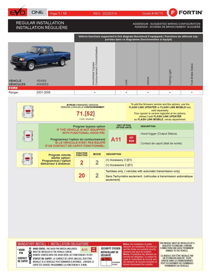
IF THE VEHICLE IS NOT EQUIPPED
WITH FUNCTIONAL HOOD PIN:
UNIT OPTION DESCRIPTION
A11 OFF Hood trigger (Output Status).
Gently pull up the top of the
steering column between the
steering wheel and the dash.
Stop when you feel resistance.
Right of Steering Column
Left of Steering Column
2
Under the Steering Column
Unscrew.
Unscrew.
Unscrew.
3
4
1
Page 2 / 11
DESCRIPTION
Ignition barrel
Ignition Connector
IMMO connector
OBDII
Front view
12345678
910111213141516
1
CAN
SW
Pin-1
Ignition
Pin-1
12V
Pin-2
VData
Pin-4
Data
Pin-2
Immo
Power
Pin-3
Photo & Location | Photos & Emplacements
Page 3 / 11
Yellow In A1
Purple In A2
Purple/White In A3
Green Out A4
White Out A5
Orange In A6
Orange/Black In A7
Dk.Blue In A8
Red/Blue In A9
Lt.Blue/Black A10
Black Out A11
Pink Out A12
Yellow/Black In A13
Brown/White Out A14
Pink/Black Out A15
Purple/Yellow A16
Green/White A17
Green/Red A18
White/Black A19
Lt.Blue A20
C5 Brown
C4 Gray/Black
C3 Gray
C2 Orange/Brown
C1 Orange/Green
D6 White/Red
D5 White/Blue
D4 White/Green
D3 Yellow/Red
D2 Yellow/Blue
D1 Yellow/Green
AC
D
Page 4 / 11
AUTOMATIC TRANSMISSION WIRING CONNECTION
CAN SW
WITH | AVEC DATA-LINK:
ALWAYS REQUIRED
NOT REQUIRED WITH
DATALINK
B
REMOTE
STARTER
WITH | AVEC DATA-LINK:
Direct connection
HOOD IN RS8
(-)
HAND BRAKE IN RS9
(-)
TRUNK RELEASE
(-) OUT RS11
(+/-) IN RS12
TACHOMETER
F
OOT
B
RAKE
(+)
IN RS13
GROUND OUT WHILE RUNNING
(-) OUT RS14
TRUNK
(-)
IN RS15
DOOR
(-) IN RS16
UNLOCK
(-) OUT RS17
LOCK
(-) OUT RS18
A15
A14
A13
A12
A11
A8
A5
A4
A3
A2
Ground | Masse
(-)
RS1
12V BATTERY
RS2 IN
(+)
PARKING LIGHTS
RS3 OUT (-)
IGNITION
RS6 IN/OUT (+)
STARTER
RS7 OUT (+)
(-) Hood Status
(-) Hand Brake
(-) Trunk Release
(-/+) Tachometer
(+) Foot Brake
(-) Ground While Running
(-) Trunk Status
(-) Door Status
(-) Unlock
(-) Lock
(+) Ignion
A2
A3
A4
A5
A6
A7
A8
A9
A10
A11
A12
A13
A14
A15
A16
A17
A18
A19
A20
C5
C4
C3
C2
C1
D6
D5
D4
D3
D2
D1
A1
D1
D5
C1
C2
C3
C4
A19
A17
A7
A6
1 2 3 4 5 6 7 8
9 10 11 12 13 14 15 16
CAN SW
PIN-1
OBDII
Front view
(~)IMMO DATA
PIN-2
(~)IMMO POWER
PIN-3
Back view
Ignition
Connector
Key Bypass
IMMO connector
Back view
Connector Burgundy
Ignition barrel
2 1
3
4
6
(+)IGNITION
PIN-1
(+)12V
PIN-2
(~) VDATA
PIN-4
123
(-) PARKING
LIGHTS
At Parking Light
switch
Trax Lt. Blue
CUT
214
Red/Yellow Purple/BlackGreen/Purple Gray/Black White/Purple
23
5
Pin 5
Empty
vide 1
Green
C5
D6
D4
A10/A20
RS3
A9
A18
A16
RS2/D2 RS7/D3
A1
D3
D2
IMMO POWER
(+)IGNITION
(+)12V
IMMO POWER
(~) VDATA
A16
(+)Start
(~)Immo Data
(~)Immo Data
(~)Immo Power
2 Amp
Fuse
WIRE TO WIRE Connection Diagram - Automatic Transmission | Diagramme de Branchements FIL À FIL - Transmission Automatique
Yellow In A1
Purple In A2
Purple/White In A3
Green Out A4
White Out A5
Orange In A6
Orange/Black In A7
Dk.Blue In A8
Red/Blue In A9
Lt.Blue/Black A10
Black Out A11
Pink Out A12
Yellow/Black In A13
Brown/White Out A14
Pink/Black Out A15
Purple/Yellow A16
Green/White A17
Green/Red A18
White/Black A19
Lt.Blue A20
C5 Brown
C4 Gray/Black
C3 Gray
C2 Orange/Brown
C1 Orange/Green
D6 White/Red
D5 White/Blue
D4 White/Green
D3 Yellow/Red
D2 Yellow/Blue
D1 Yellow/Green
AC
D
MANUAL TRANSMISSION WIRING CONNECTION
CAN SW
WITH | AVEC DATA-LINK:
ALWAYS REQUIRED
NOT REQUIRED WITH
DATALINK
B
REMOTE
STARTER
WITH | AVEC DATA-LINK:
Direct connection
HOOD IN RS8
(-)
HAND BRAKE IN RS9
(-)
TRUNK RELEASE
(-) OUT RS11
(+/-) IN RS12
TACHOMETER
F
OOT
B
RAKE
(+)
IN RS13
GROUND OUT WHILE RUNNING
(-) OUT RS14
TRUNK
(-)
IN RS15
DOOR
(-) IN RS16
UNLOCK
(-) OUT RS17
LOCK
(-) OUT RS18
A15
A14
A13
A12
A11
A8
A5
A4
A3
A2
Ground | Masse
(-)
RS1
12V BATTERY
RS2 IN
(+)
PARKING LIGHTS
RS3 OUT (-)
IGNITION
RS6 IN/OUT (+)
STARTER
RS7 OUT (+)
STARTER
RS8 OUT (-)
(-) Hood Status
(-) Hand Brake
(-) Trunk Release
(-/+) Tachometer
(+) Foot Brake
(-) Ground While Running
(-) Trunk Status
(-) Door Status
(-) Unlock
(-) Lock
(+) Ignion
A2
A3
A4
A5
A6
A7
A8
A9
A10
A11
A12
A13
A14
A15
A16
A17
A18
A19
A20
C5
C4
C3
C2
C1
D6
D5
D4
D3
D2
D1
A1
D1
D5
C1
C2
C3
C4
A19
A17
A7
A6
1 2 3 4 5 6 7 8
9 10 11 12 13 14 15 16
CAN SW
PIN-1
OBDII
Front view
(~)IMMO DATA
PIN-2
(~)IMMO POWER
PIN-3
Back view
Ignition
Connector
Key Bypass
IMMO connector
Back view
Ignition barrel
2 1
3
4
6
(+)IGNITION
PIN-1
(+)12V
PIN-2
(~) VDATA
PIN-4
123
1 2 3
(-) CLUTCH
Back view, 3-Pin
Black
connector, at
Switch.
(-) PARKING
LIGHTS
At Parking Light
switch
Trax Lt. Blue
CUT
214
Red/Yellow Purple/BlackGreen/Purple Gray/Black White/Purple
23
5
Pin 5
Empty
vide 1
Green
2
Yellow
C5
D6
D4
A10/A20
RS3
A9
A18
A16
RS2/D2 RS7/D3
A1
D3
D2
IMMO POWER
(+)IGNITION
(+)12V
IMMO POWER
(~) VDATA
A16
(+)Start
(~)Immo Data
(~)Immo Data
(~)Immo Power
2 Amp
Fuse
RS8
180 ohm
Resistor
WIRE TO WIRE Connection Diagram - Manual Transmission | Diagramme de Branchements FIL À FIL - Transmission Manuelle
Page 5 / 11
Yellow In A1
Purple In A2
Purple/White In A3
Green Out A4
White Out A5
Orange In A6
Orange/Black In A7
Dk.Blue In A8
Red/Blue In A9
Lt.Blue/Black A10
Black Out A11
Pink Out A12
Yellow/Black In A13
Brown/White Out A14
Pink/Black Out A15
Purple/Yellow A16
Green/White A17
Green/Red A18
White/Black A19
Lt.Blue A20
C5 Brown
C4 Gray/Black
C3 Gray
C2 Orange/Brown
C1 Orange/Green
D6 White/Red
D5 White/Blue
D4 White/Green
D3 Yellow/Red
D2 Yellow/Blue
D1 Yellow/Green
AC
D
THAR-GM1V2 | AUTOMATIC TRANSMISSION CONNECTION
CAN SW
1Amp. current Maximum
B
WITH DATA-LINK:
WITH D2D:
OR
Blue
White
B2
B1
Black
Red 12V BATTERY
GROUND
B4
B3
WITHOUT DATA-LINK:
B4
B3
B2
B1
Cut | Coupez Red
Black
Cut | Coupez
ALWAYS REQUIRED
NOT REQUIRED WITH
DATALINK
REMOTE
STARTER
WITH | AVEC DATA-LINK:
Direct connection
Ground | Masse
(-)
RS1
12V BATTERY
RS2 IN
(+)
PARKING LIGHTS
RS3 OUT (-)
ACCESSORY
RS5 OUT (+)
IGNITION
RS6 IN/OUT (+)
STARTER
RS7 OUT (+)
A2
A3
A4
A5
A6
A7
A8
A9
A10
A11
A12
A13
A14
A15
A16
A17
A18
A19
A20
C5
C4
C3
C2
C1
D6
D5
D4
D3
D2
D1
A1
D1
D5
C1
C2
C3
C4
A19
A17
A7
1 2 3 4 5 6 7 8
9 10 11 12 13 14 15 16
CAN SW
PIN-1
OBDII
Front view
(-) PARKING
LIGHTS
At Parking Light
switch
Trax Lt. Blue
1
Green
Yellow
Brown
C5
6 PIN CONN.
T-HARNESS | HARNAIS EN T : THAR-GM1 V2
A16
HOOD IN RS10
(-)
HAND BRAKE IN RS11
(-)
TRUNK RELEASE
(-) OUT RS12
(+/-) IN RS13
TACHOMETER
F
OOT
B
RAKE
(+)
IN RS14
HEATED SEATS
(-) IN RS16
GROUND OUT WHILE RUNNING
(-) OUT RS15
TRUNK
(-)
IN RS17
DOOR
(-) IN RS18
UNLOCK
(-) OUT RS19
LOCK
(-) OUT RS20
A15
A14
A13
A12
A6
A11
A8
A5
A4
A3
A2
(-) Heated Seats
(-) Trunk Status
(-) Door Status
(-) Unlock
(-) Lock
(-) Ground While Running
(+)Start
(-) Hood Status
(-) Hand Brake
Trunk Release
(-/+) Tachometer
(+) Foot Brake
RS3
Make the connection
Back view Ignition Connector
Ignition barrel
Key Bypass
IMMO connector
Back view
THAR-GM1V2 - THarness Diagram - Automatic Transmission | Diagramme harnais en T - Transmission Automa-
tique
Page 6 / 11
Yellow In A1
Purple In A2
Purple/White In A3
Green Out A4
White Out A5
Orange In A6
Orange/Black In A7
Dk.Blue In A8
Red/Blue In A9
Lt.Blue/Black A10
Black Out A11
Pink Out A12
Yellow/Black In A13
Brown/White Out A14
Pink/Black Out A15
Purple/Yellow A16
Green/White A17
Green/Red A18
White/Black A19
Lt.Blue A20
C5 Brown
C4 Gray/Black
C3 Gray
C2 Orange/Brown
C1 Orange/Green
D6 White/Red
D5 White/Blue
D4 White/Green
D3 Yellow/Red
D2 Yellow/Blue
D1 Yellow/Green
AC
D
THAR-GM1V2 | MANUAL TRANSMISSION CONNECTION
CAN SW
1Amp. current Maximum
B
WITH DATA-LINK:
WITH D2D:
AVEC D2D:
OR
Blue
White
B2
B1
Black
Red 12V BATTERY
GROUND
B4
B3
WITHOUT DATA-LINK:
B4
B3
B2
B1
Cut | Coupez Red
Black
Cut | Coupez
ALWAYS REQUIRED
NOT REQUIRED WITH
DATALINK
REMOTE
STARTER
WITH | AVEC DATA-LINK:
Direct connection
Ground | Masse
(-)
RS1
12V BATTERY
RS2 IN
(+)
PARKING LIGHTS
RS3 OUT (-)
ACCESSORY
RS5 OUT (+)
IGNITION
RS6 IN/OUT (+)
STARTER
RS7 OUT (+)
STARTER
RS8 OUT (-)
A2
A3
A4
A5
A6
A7
A8
A9
A10
A11
A12
A13
A14
A15
A16
A17
A18
A19
A20
C5
C4
C3
C2
C1
D6
D5
D4
D3
D2
D1
A1
D1
D5
C1
C2
C3
C4
A19
A17
A7
1 2 3 4 5 6 7 8
9 10 11 12 13 14 15 16
CAN SW
PIN-1
OBDII
Front view
1 2 3
(-) CLUTCH
Back view, 3-Pin
Black
connector, at
Switch.
(-) PARKING
LIGHTS
At Parking Light
switch
Trax Lt. Blue
1
Green
2
Yellow
Yellow
Brown
C5
6 PIN CONN.
T-HARNESS | HARNAIS EN T : THAR-GM1 V2
A16
HOOD IN RS10
(-)
HAND BRAKE IN RS11
(-)
TRUNK RELEASE
(-) OUT RS12
(+/-) IN RS13
TACHOMETER
F
OOT
B
RAKE
(+)
IN RS14
HEATED SEATS
(-) IN RS16
GROUND OUT WHILE RUNNING
(-) OUT RS15
TRUNK
(-)
IN RS17
DOOR
(-) IN RS18
UNLOCK
(-) OUT RS19
LOCK
(-) OUT RS20
A15
A14
A13
A12
A6
A11
A8
A5
A4
A3
A2
(-) Heated Seats
(-) Trunk Status
(-) Door Status
(-) Unlock
(-) Lock
(-) Ground While Running
(+)Start
(-) Hood Status
(-) Hand Brake
Trunk Release
(-/+) Tachometer
(+) Foot Brake
RS3
Make the connection
RS8
180 ohm
Resistor
Back view Ignition Connector
Ignition barrel
Key Bypass
IMMO connector
Back view
Connector Burgundy
THAR-GM1V2 - THarness Diagram - Manual Transmission | Diagramme harnais en T - Transmission Manuelle
Page 7 / 11
RELEASE
PROGRAMMING PROCEDURE 1/2 | PROCÉDURE DE PROGRAMMATION 1/2
x
x
5
5
Release the programming
button when the LED is
YELLOW.
If the LED is not solid YELLOW
disconnect the 4-Pin connector
(Data-Link) and go back to step
ON
Insert the required remaining connectors.
FLASH
FLASH
FLASH
ON
2
3
4
OFF
OFF
ON
ON
6
Press and release the programming
button five times (5x).


The YELLOW LED will alternate
between 5x flashes and a pause.
Wait until the YELLOW LED turns ON.
IGNITION OFF IGNITION ON
FLASH
FLASH
LOCK
ACC ON
PUSH
START
IGN
LOCK
ACC ON
PUSH
START
OFF
7
LOCK
ACC ON
START
PUSH
5
If the LED is not solid RED
disconnect the 4-Pin connector
(Data-Link) and go back to
step 1.
1
CETTE PROGRAMMATION EST POUR LES
EVO-ALL_GM_INDIVIDUEL.indd
Prog. pour Cruze et cie special pour europe
The RED AND BLUE LEDs will
flash rapidly ten (10) times.
Les DELs ROUGE et BLEU
clignoteront dix (10) fois
rapidement.
The BLUE LED will flash
rapidly.
La DEL BLEU clignotera
rapidement.
FLASH 10X
IGNITION ON
FLASH 10X
FLASH
WAIT
If the LED is solid RED
disconnect the 4 Pin
connector (Data-Link) and go
back to step 1.
Si le DEL est ROUGE solide
débranchez le connecteur 4
pins (Data-Link) et allez à
l'étape 1.
Parts required (not included) Pièces requises (non incluses)
1x ,
1x software
1x Microsoft Windows Computer with
Internet connection
FLASH LINK UPDATER
FLASH LINK
2
MANAGER
1x ,
1x Programme
1x Ordinateur Microsoft Windows avec
connection Internet
FLASH LINK UPDATER
FLASH LINK
2
MANAGER
Press and hold the
programming button:
Connect
the 4-PIN Data-link
harness (Black connector).
 The Blue, Red, Yellow and
Blue & Red LEDs will
alternatively illuminate.
 The RED LED will turns ON.
 The YELLOW LED turns
OFF.
Turn the key to the
Ignition ON/RUN position.
Turn the key to the
OFF position.
Remove the key
from the Ignition
barrel.
xx11
HOLD
LED may differ depending on the module casing.
DCRYPTOR PROGRAMMING PROCEDURE
1x FLASH LINK UPDATER,
1x FLASH LINK MANAGER
1x FLASH LINK MOBILE
1x FLASH LINK MOBILE APP
Smartphone Android or iOS with Internet connection
(Internet provider charges may apply)
OR
OU
Microsoft Windows Computer with Internet connection
1x1x
Key Bypass Programming Procedure | Procédure de Programmation Contournement de Clé
Page 8 / 11
Parts required (not included)
SOFTWARE
BEFORE PROGRAMMING SET THE UNIT OPTIONS AND SAVE.
CONTINUED NEXT PAGE
Turn the Ignition to the ON position.
The BLUE LED will turns ON.
Wait, the BLUE & RED LED will turns OFF
.
Wait, the YELLOW LED will Flash.
Wait,the YELLOW LED will turns OFF.
Wait,the BLUE LED will Flash rapidly.
Wait 5 seconds.
the BLUE LED flash slowly.
Turn the key to the
OFF position.
LOCK
ACCON
PUSH
START
IGN
LOCK
ACCON
PUSH
START
OFF
IF THE VEHICLE IS
NOT EQUIPPED WITH
THE ON-STAR®
SYSTEM.
SI LE VÉHICULE NʼEST
PAS ÉQUIPÉ DU
SYSTÈME ON-STAR®
FLASH
SLOWLY

FLASH RAPIDLY
ON

ON

OFF
ON
OFF
FLASH OFF
WAIT If the LEDs do not react as
shown, disconnect the 4-Pin
connector (Data-Link) and go
back to step 1.
9
10
8
KEY BYPASS PROGRAMMING PROCEDURE 2/2 |
EVO-ALL
Disconnect all the connectors and after
the Data-Link (4-pins) connector.
REMOTE STARTER / ALARM VERIFICATION
Test the remote starter. Remote start the vehicle.
The module is now programmed.
Use the tool:
FLASH LINK UPDATER or
FLASH LINK MOBILE
to visit the DCryptor menu.
*Parts required (not included)
FLASH LINK UPDATER*
FLASH LINK MOBILE*
FLASH LINK MANAGER*
Microsoft Windows
Computer with
Internet connection*
VEHICLE'S OBDII
CONNECTOR
OR
OU
Smartphone*
(Internet provider
charges
may apply)
AFTER DCRYPTOR PROGRAMMING COMPLETED
Go back to the vehicle and reconnect the 4-Pin (Data-Link)
connector and after, all the remaining connector.
EVO-ALL
11
12
13
Page 9 / 11
SOFTWARE
PROCEDURE
Remote start the
vehicle.
All doors must
be closed.
Start
UNLOCK
Unlock the doors with
the remote-starter
remote or the OEM
remote.
Insert and Turn
the key to the
Ignition ON/RUN
position.
The vehicle can
now be put in to
gear and driven.
Press
the brake pedal.
ON
TURN
ON/RUN
REMOTE STARTER FUNCTIONALITY |
Remote starter functionality | Fonctionalité du démarreur à distance
Page 10 / 11
*HOOD PIN HOOD STATUS: THE HOOD PIN SWITCH MUST BE INSTALLED
IF THE VEHICLE CAN BE REMOTE STARTED WITH THE HOOD OPEN,
SET FUNCTION A11 TO OFF.
MANDATORY INSTALL Notice: the installation of safety
elements are mandatory. The hood pin
is an essential security element and
must be installed.
THIS MODULE MUST BE INSTALLED BY A
QUALIFIED TECHNICIAN. A WRONG
CONNECTION CAN CAUSE PERMANENT
DAMAGE TO THE VEHICLE.
A11 OFF
ADDENDUM - SUGGESTED WIRING CONFIGURATION
ALL REV.: 20210914
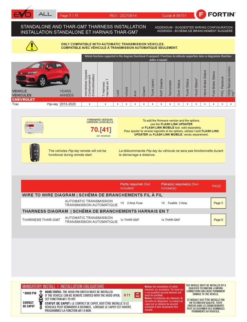
ONLY COMPATIBLE WITH AUTOMATIC TRANSMISSION VEHICLES.
FIRMWARE VERSION To add the rmware version and the options,
use the FLASH LINK UPDATER
or FLASH LINK MOBILE tool, sold separately.
70.[41]
GM MINIMUM
The vehicles Flip-key remote will not be
functional during remote start.
Parts required (Not
included) PAGE
WIRE TOWIRE DIAGRAM
AUTOMATIC TRANSMISSION 1X 2 Amp Fuse Page 5
THARNESS DIAGRAM
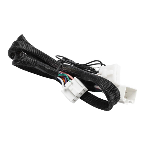
THARNESS THAR-GM7 AUTOMATIC TRANSMISSION 1x THAR-GM7 Page 6
Guide # 98141
Vehicle functions supported in this diagram (functional if equipped)
VEHICLE YEARS
Immobilizer bypass
T-Harness
Lock
Unlock
Arm
Disarm
Trunk (open)
RAP Disable
Tachometer
Door Status
Trunk Status
Hood Status*
Hand-Brake Status
Foot-Brake Status
PK3, Passlock
OEM Remote monitor-
ing**
CHEVROLET
Trax
Flip-key
2013-2020
•
•
•
•
•
•
•
•
•
•
•
•
•
•
•
•
Supported functions & Function programming | Fonctions supportées et programmation des
fonctions
STANDALONE AND THAR-GM1V2 THARNESS
INSTALLATION
Page 1 / 11
NOTES
Program bypass option:
UNIT OPTION DESCRIPTION
C1
OEM Remote status (Lock/Unlock)
monitoring
ATTENTION! Type X
Made in Canada
PATENTSPENDING US: X
Waranty void if opened
Service # : X
HARDWARE VERSION X
FIRMWARE VERSION X
EVO-ALL
Date: xx-xx
DATE: XX-XX
E5
OFF SPECIAL FUNCTIONS:
BY DEFAULT DEACTIVATED
ON
Program bypass option
(If equiped with OEM alarm): D2
Unlock before / Lock after (Disarm OEM
alarm)
IF THE VEHICLE IS NOT EQUIPPED
WITH FUNCTIONAL HOOD PIN: A11 OFF Hood trigger (Output Status).
NOTE | NOTES
Page 2 / 11

Other Fortin Automobile Accessories manuals
Fortin EVO-ONE User manual

Fortin

Fortin EVO-ONE User manual

Fortin EVO ONE User manual

Fortin

Fortin EVO ONE User manual

Fortin EVO-CAN User manual

Fortin

Fortin EVO-CAN User manual

Fortin EVO ONE User manual

Fortin

Fortin EVO ONE User manual

Fortin EVO ONE THAR-ONE-HON7 User manual

Fortin

Fortin EVO ONE THAR-ONE-HON7 User manual

Fortin EVO KEY User manual

Fortin

Fortin EVO KEY User manual

Fortin Evo One THAR-ONE-HON4 User manual

Fortin

Fortin Evo One THAR-ONE-HON4 User manual

Fortin PATS-GM2 User manual

Fortin

Fortin PATS-GM2 User manual

Fortin EVO-ALL User manual

Fortin

Fortin EVO-ALL User manual

Fortin EVO ONE User manual

Fortin

Fortin EVO ONE User manual

Fortin EVO ONE User manual

Fortin

Fortin EVO ONE User manual

Fortin EVO ONE User manual

Fortin

Fortin EVO ONE User manual

Fortin EVO ONE User manual

Fortin

Fortin EVO ONE User manual

Fortin EVO ALL User manual

Fortin

Fortin EVO ALL User manual

Fortin EVO-ALL THAR-FOR1 User manual

Fortin

Fortin EVO-ALL THAR-FOR1 User manual

Fortin EVO ONE Installation and operating instructions

Fortin

Fortin EVO ONE Installation and operating instructions

Fortin EVO ONE THAR-GM7 User manual

Fortin

Fortin EVO ONE THAR-GM7 User manual

Fortin Evo All THAR-CHR4 User manual

Fortin

Fortin Evo All THAR-CHR4 User manual

Fortin TB-SUBARU2 User manual

Fortin

Fortin TB-SUBARU2 User manual

Fortin EVO ONE User manual

Fortin

Fortin EVO ONE User manual

Fortin EVO ONE User manual

Fortin

Fortin EVO ONE User manual

Fortin Evo All THAR-FOR3 User manual

Fortin

Fortin Evo All THAR-FOR3 User manual
Fortin Evo One THAR-ONE-TOY1 User manual
Fortin

Fortin Evo One THAR-ONE-TOY1 User manual

Fortin EVO-CAN User manual

Fortin

Fortin EVO-CAN User manual

Popular Automobile Accessories manuals by other brands

Redarc FK40 manual

Redarc

Redarc FK40 manual

PUTCO 470210 installation instructions

PUTCO

PUTCO 470210 installation instructions

Hella Flying Clutch II Mounting instructions

Hella

Hella Flying Clutch II Mounting instructions

pewag Universal ED Mounting instructions

pewag

pewag Universal ED Mounting instructions

FILTRON K 1011 installation instructions

FILTRON

FILTRON K 1011 installation instructions

LOADHANDLER LH2200 instruction manual

LOADHANDLER

LOADHANDLER LH2200 instruction manual

James Baroud Space user guide

James Baroud

James Baroud Space user guide

Improved Racing EFR-600-TX quick start guide

Improved Racing

Improved Racing EFR-600-TX quick start guide

TrailFX RBW10B quick start guide

TrailFX

TrailFX RBW10B quick start guide

Sonorix A1 user manual

Sonorix

Sonorix A1 user manual

AMP Research 75135-01A installation guide

AMP Research

AMP Research 75135-01A installation guide

Roadmaster FuseMaster 76512 Installation and operating instructions

Roadmaster

Roadmaster FuseMaster 76512 Installation and operating instructions

Holland TL4048 Series installation manual

Holland

Holland TL4048 Series installation manual

Volvo 30775790 installation instructions

Volvo

Volvo 30775790 installation instructions

RITE-HITE DOK-LOK VBR-600 installation manual

RITE-HITE

RITE-HITE DOK-LOK VBR-600 installation manual

Front Runner TBRA034 manual

Front Runner

Front Runner TBRA034 manual

Front Runner RRAC203 manual

Front Runner

Front Runner RRAC203 manual

Camcar 40054 AL Mounting instructions

Camcar

Camcar 40054 AL Mounting instructions

manuals.online logo
manuals.online logoBrands
  • About & Mission
  • Contact us
  • Privacy Policy
  • Terms and Conditions

Copyright 2025 Manuals.Online. All Rights Reserved.