WARNING!
With Power Switch “ON,” door open and steps extended, it is possible to drive off. Damage to steps or vehicle is possible, as well
asseriouspersonalbodilyinjuryordeath.
STEPOPERATION - POWER “OFF”
1. Withdooropen,stepsextendedandPowerSwitchturned“OFF,”stepsremainextended; amberlightshutsoff.
2. Ifthestepsaretoberetractedwiththedooropen,turnthe power switch ON, retract thestepsandturnpowerswitchOFF. Thestepswill
remainretracted.
3. Withdoorclosed,stepsextendedandPowerSwitch“OFF,”turningtheignition“ON”willautomaticallyretractsteps.
4. Whendoorisopened andignition turnedoff,stepswill extend onelasttime- lastmanoutfeature.
5. Ifdoorisopenedandclosedwithoutfull extension ofthesteps,thestepswillretractandstayuntilPower Switch is turned “ON” anddoor
reopened.
NOTE: Ifstep’sfullextensionisimpededbyan external object likeacurb,stepswillceaseoperation and shutdown. Stepswillretractnormally.
TROUBLESHOOTING
WARNING!
Steps must always be operated with a fully chargedbattery. Because the stepscandetectobstaclesin the way of operation by
sensingexcessiveamperage,afullychargedbatteryisimperative. Anydropinvoltagewillcausethestepstomalfunction.
WARNING!
With Power Switch “ON,” door open and steps extended, it is possible to drive off. Damage to steps or vehicle is possible, as well
asseriouspersonalbodilyinjuryordeath.
WARNING!
Due to the fact that the step detects obstacles by sensing excessive current draw, it is imperative that the step be tested with a fully
charged battery and test wires be at least 12 GA. Do not attempt to test the steps using a battery charger or bench type power
supply. Even though they may supply a full 12VDC, a momentary drop in the supply may fool the module into thinking that the
steps have encountered an obstacle.If using a battery to test the steps, care should be taken to connect jumpers to the battery
first and then to the steps. Battery acid can cause injury and automotive type batteries under load can produce hydrogen gas.
They may explode if shorted out or if a spark ignites the hydrogen gas when the battery is connected to a load.
WARNING!
No repairs should be attempted by anyone other than a qualified professional as the deployment or retraction of the steps can
cause injury if proper precautions are not taken.
TROUBLESHOOTING THE SYSTEM
1. Disconnecttheplugbetweenthechassisandthesteps. Usinga voltmeter, measure the voltageonthelargeredwireatthechassis
connectorwiththestepswitchinthe“ON”position. Themetershouldindicatemorethan12VDC. Turnthestepswitchtothe“OFF”position
andthemetershouldnotindicatevoltage. Ifthemeter indicated no voltage with the switch “ON”,checkthecircuitandthecircuitprotectors.
Ifitindicateslessthan12VDCwiththeswitch“ON”,chargethe battery. If 12VDCareindicatedontheredwirewiththeswitch“OFF”,replace
theswitch.
2. Withthevoltmeter,settomeasure resistance,measuretheresistancebetweenthegreenwirein theplugandtheframeofthevehicle. Ifthere
ismorethanoneohmofresistance,cleanthegroundeye(groundlug)orrelocatethegroundwire.
3. Usingavoltmeter,settoresistance,testforgroundonthebrownwiregoingtothedoorswitch. Themetershouldindicateanopen circuit
withthedoorclosedand a path to the groundwiththedooropen. Insurethatthedoorisopenatleast6inchesbeforeitcompletesthecircuit
to ground.
4. Withavoltmeter,checkfor12VDContheyellowwirewiththe ignition switch in the“ON”positionandnovoltagewiththeswitchinthe“OFF”
position. If there is no voltagewiththeswitch in the “ON” position, trace thecircuitandrepair.
5. Reconnectthestepstothechassisandproceedto test asfollows. Withstepswitch“ON”andtheignitionkey“OFF”opentheentrydoor and
thesteps should extendandthelightshouldcomeon.
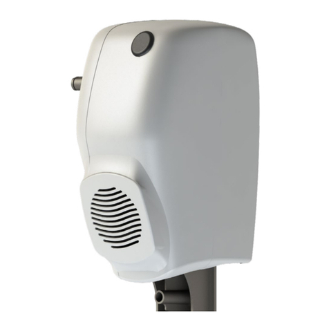
6. Ifthelightcomeson,butthestepsdonotdeploy,removethestepassemblyfromthemotorhome.
7. Removethetwoboltsthathold thesteparmcollarstothedriveshaft. Thiswillallowyoutooperatethestepsmanually. Ifthestepsdonot
operatefreely, visually inspect for bent arms or tight joints. The shoulder boltsshouldrotateinthebushingswithverylittleeffort. Repairor
replaceasneeded.
8. Ifthestepmoves freely,unplugthemodule fromthemotorassemblyatthe twopinconnector. Connect12VDCfromthe batterytotheyellow
wiregoingtothemotorandgroundtheredwire. Thegearshouldrotateinthedeploymentdirectionuntilitgoesovercenterandcomesto
restagainstthestop. (Ifthestepsweredeployed,reversethewirestodrivethegearintheoppositedirection). Ifthegearandmotor
assemblywillnotfunctionnormally replacethem,otherwisereplacethemoduleassembly.
