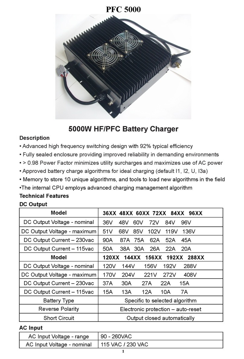
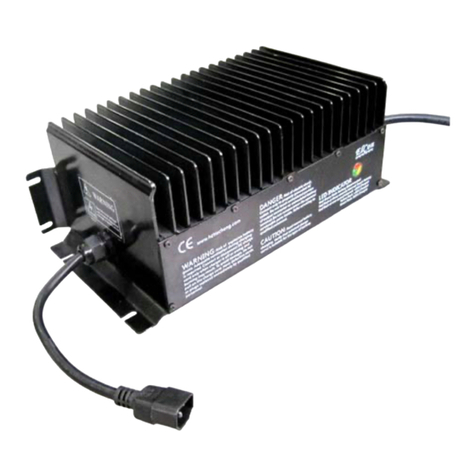
Elcon pfc3000 User manual

3000W HF/PFC Battery Charger
Description
• Advanced high frequency switching design with 92% typical efficiency
• Fully sealed enclosure provides improved reliability in demanding environments
• > 0 98 Power Factor minimizes utility surcharges and maximizes use of AC power
• Approved battery charge algorithms for ideal charging (default I1, I2, U, I3a)
• Memory to store 10 unique algorithms, and tools to load new algorithms in the field
•The internal CPU employs advanced charging management algorithm
Technical Features
DC Output
24XX 36XX 48XX 60XX 72XX 96XX 120XX 144XX
DC Output Voltage - nominal 24V 36 V 48 V 60V 72V 96V 120V 144V
DC Output Voltage - maximum 34V 51 V 68 V 85V 102V 136V 170V 204V
DC Output Current - maximum 80A 60 A 50 A 40A 32A 24A 20A 16A
Battery Type Specific to selected algorithm
Reverse Polarity Electronic protection – auto-reset
Short Circuit Output closed automatically
AC Input
AC Input Voltage - range 90 - 260VAC
AC Input Voltage - nominal 120 VAC / 230 VAC
AC Input Frequency 45 - 65 Hz
AC Input Current - maximum 30A
Current – nominal 25 A rms @ 120 VAC / 13 A rms @ 230 VAC
AC Power Factor - nominal > 0 98
Mechanical
Dimensions 352mm×252mm×168mm
Weight <9 75 kg Standard output cord
Environmental Enclosure IP46
Operating Temperature -30°C to +50°C (-86°F to 122°F)
1

Storage Temperature -40°C to +85°C (-104°F to 185°F)
ED Indicator
Red-Green flash (one second interval) Battery Disconnected
Red flash (three seconds interval) Repair Battery
Red flash (one second interval) <80% Charge Indicator
Yellow flash (one second interval) >80% Charge Indicator
Green flash (one second interval) 100% Charge Indicator
Protection Features
1 Thermal Self-Protection: When the internal temperature of the charger exceeds
80℃, the charging current will reduce automatically If exceeds 85℃, the charger will
shutdown protectively, there is no current output in this case When the internal
temperature drops to 80℃, it will resume charging automatically
2 Short-circuit Protection: when the charger encounters unexpected short circuit
across the output, charging will automatically stop By cutting AC power for 10
seconds, the charger can be re-set and will start normally(with the output circuit
corrected)
3 High and Low Voltage Protection: when the input AC Voltage is higher or lower
than the rated input voltage range, the charger will shutdown protectively, but
resume working after the voltage is normal again
Inter-lock Function
When it discharges, the internal electrical relay connects the blue and red wire, and
outputs battery voltage During the charging, the blue wire disconnects the internal
connection, and no voltage outputs
Note: Do not let the current on green wire flow over 2A
Choice of Charging Curve (curve 1~10)
1. The LED will flash red several times when AC is first connected, then
the LED will flash green once The number of red flashes denotes the present curve
E g If the red flashes three times, it means the present curve is curve 3
2 To choose another curve, please cut off the power supply first, then unpeel the
label, pressing the button while connecting the power If you want to choose curve 3,
release the button after the 3rd LED Flash Now the selected curve (e g curve 3) will
be recorded in memory If you want the charger to work with the selected curve (e g
2

curve 3), cut off the power and reconnect it
Alarms
LED Flashing Sequence(One Cycle) Indication
1 R G _ _ _ _ _ _ Wrong Battery
2 R G R _ _ _ _ _ Overcharged
3 R G R G _ _ _ _ The temperature of battery is too high
4 R G R G R _ _ _ Incorrect AC Input Voltage
5 R G R G R G _ _ The thermal sensor of charger is in fault
6 R G R G R G R _ The interface of communication is in fault
7 G R _ _ _ _ _ _ The temperature of charger is too high
8 G R G _ _ _ _ _ The relay of charger is in fault;Repair
9 G R G R _ _ _ _ Charger is in fault; Repair
Note: 1 R—red G—green
2 “_” denotes one second stop
3 Above LED flashing sequence is just one cycle, the LED will flash
repeatedly when in fault
Installation & Safety Instructions
Our charger has been designed to provide safety and reliability It is important to
observe the following precautions and installation instructions in order to avoid
damage to persons and to the battery charger For further reference keep the
instruction in a proper place
1 Fix the battery charger to a stable surface with the holes inserted on the mounting
tabs In case of installation on a vehicle, it is advisable to use anti-vibration supports
2 Preferably the charger should be installed in the vertical position with radiator fins
vertical A space of 10cm above ground should be vacated, to ensure it is ventilated
Never install in the vertical position with fins facing down Refer to drawing below:
3 Ensure all heat dissipating parts are not obstructed to avoid overheating Do not
put the battery charger near any heat sources Make sure that free space around the
battery charger is sufficient to provide adequate ventilation and easy access to cable
sockets
4 For safety and electromagnetic compatibility the battery charger has a 3-prong
plug that will only plug into a proper grounded outlet
5 To avoid damaging the power cord, do not put anything on it or place it where it
will be walked on If the cord becomes damaged or frayed, replace it immediately
6 If you are using an extension cord or power strip, make sure that the total of the
amperes required by all the equipment on the extension is less than the extension’s
3

rating
7 Verify that the selected charging curve is suitable for the type of battery to be
recharged
8 In order to avoid voltage drop, the output cables must be as short as possible, and
the diameter must be adequate for the output current
9 Do not try to service the battery charger yourself Opening the cover may expose
you to shock or other hazards
10 If the battery charger does not work correctly or if it has been damaged,
unplugged it immediately from the supply socket, from the battery and contact a
retailer
11 In the case of thermal compensation for the battery voltage, it is necessary to
place the thermal sensor in the area of the highest battery temperature, such as
between 2 batteries near the center of the pack
Attentions
To reduce the risk of electric shock, do not remove cover Refer servicing to
qualified service personnel Disconnect the mains supply before connecting or
disconnecting the links to the battery Read the instruction manual carefully before
use Verify that the selected charge curve is suitable for the type of battery you have
to re-charge
Mechanical Dimensions
All dimensions are expressed in mm
4
Table of contents
Other Elcon Batteries Charger manuals
