Elcon TCCH-48-140 User manual

HF/PFC8KWOn-boardCHARGER Lead-acidbatterycharger)
Size (mm)
357(L) 254(W) 377(H)
N.W. 27.70kg
Models
Lead-acid Battery Charger Vout Nominal VoutMax IoutMax
TCCH-48-140 48V 66V 140A
TCCH-60-120 60V 83V 120A
TCCH-72-100 72V 96V 100A
TCCH-84-84 84V 112V 84A
TCCH-96-72 96V 130V 72A
TCCH-108-64 108V 145V 64A
TCCH-120-60 120V 168V 60A
TCCH-144-48 144V 192V 48A
TCCH-156-44 156V 208V 44A
TCCH-168-40 168V 234V 40A
TCCH-180-36 180V 243V 36A
TCCH-192-36 192V 258V 36A
TCCH-216-32 216V 290V 32A
TCCH-240-29 240V 337V 29A
TCCH-288-24 288V 389V 24A
TCCH-312-22 312V 417V 22A
I ProductSummary&ApplicationScopes
The charger is applicable for various Lead-acid batteries like Flooded, GEL,AGM,hemicolloidetc.,It featureslight weight, small
volume,stable performance, highefficiencyandreliablesecurityetc., Itcanbeswitched automaticallybetweenthefloating and
balancing charging and also has the protectionfunctions of reverse connection, outputshort-circuit and overloadand so on.
Thecharger iswidely usedforbattery-charging cyclesin electric vehicles suchaselectricforklift,golf cars,electric trucks,electric
tourbus,electricyacht, cleaning machines, orUninterruptible Power Supply (UPS), solar energy,wind powerdynamo and
electric communication system on the railwayetc.
II TechnicalTarget
ACInputVoltageRange AC85V~AC265V
ACInputFrequency 45~65Hz
ACPower Factor ≥0.98
FullLoad Efficiency ≥93%
MechanicalShock&
Vibration ResistanceLevel Conformance to
SAEJ1378 Standard
EnvironmentalEnclosure IP46
OperatingTemperature -40℃~+55℃(-104℉~+131℉)
Storage Temperature -40℃~+100℃
(-104℉~+212℉)
Charging Mode 10Charging Curves
Available
Charging Control Intelligenttemperaturecompensation,
never to becharge-offorchargedue
IIIProtectionFeatures
1. ThermalSelf-Protection:Whentheinternaltemperatureofthechargerexceeds75℃,thechargingcurrentwillreduce
automatically.If itexceeds 85 ,the chargerwill shutdown protectively.Whenthe internaltemperature drops,itwill resume
charging automatically.
2.Short-circuitProtection: Whenthe chargerencountersunexpected short-circuit, itwill automaticallystoptooutput. Whenfault
removes,the chargerwill re-start in 10 seconds.
3. Reverse ConnectionProtection:When thebatteryispolarityreversed, the charger will cutofftheconnectionbetweenthe
internalcircuit and the battery, andrefusestostart.It canavoidany destroy.
4. InputLow-voltage & Over-voltage Protection:When the AC inputVoltageis lower than 85V orhigher than265V, the charger
will shutdownprotectivelyandautomaticallyresumeworking withthe voltage is normal again.
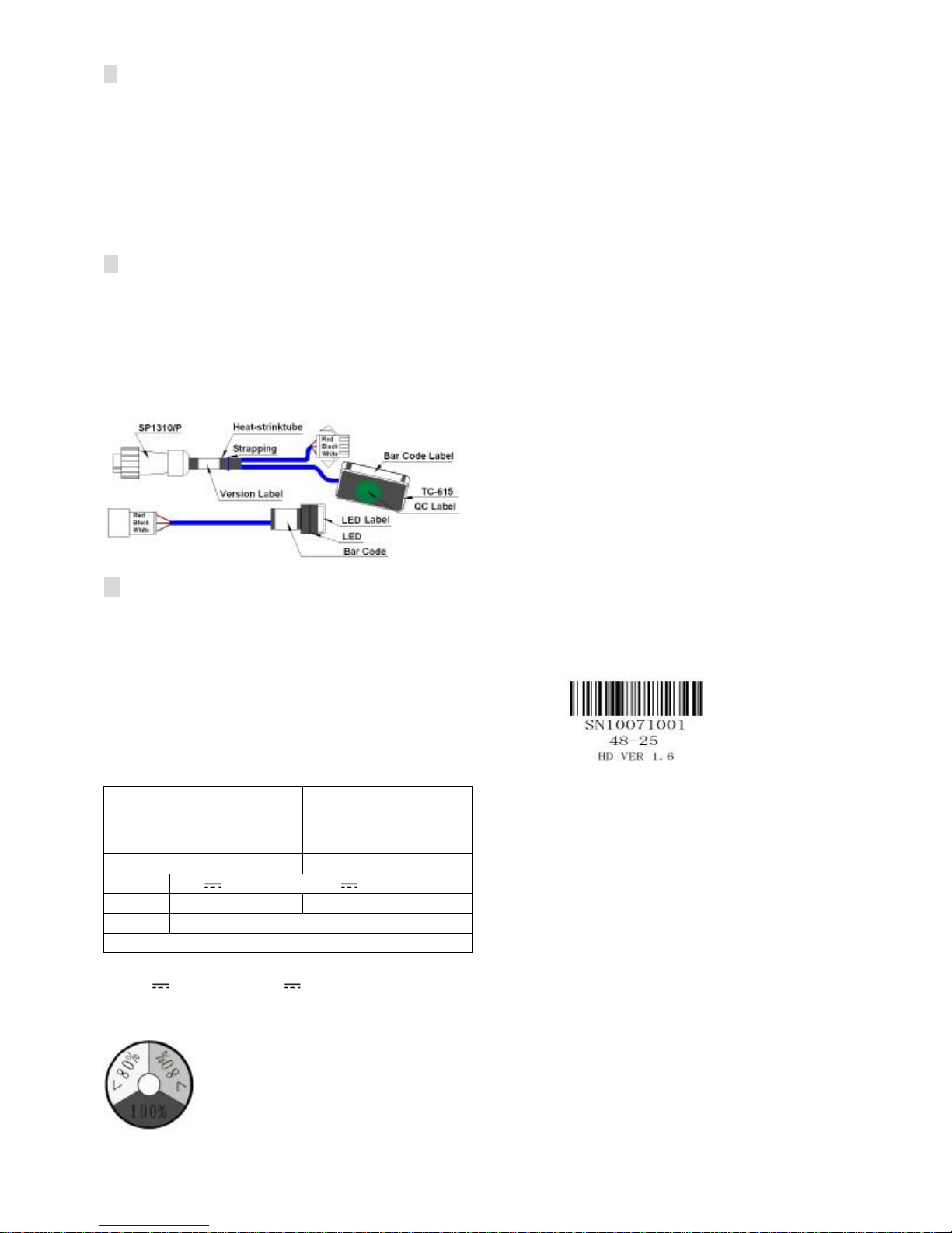
IV MainAccessories&WiringDiagram
Accessories:
ThermalSensor TC-615together withLED TC-618 (asper the specific vehiclemodel)ora singleThermalSensor TC-615.
Functions:
ThermalsensorTC-615providesthereal-timedetectionofthebattery’stemperatureinthecharging processtoprevent
charge-offorchargedue.
LED TC-618showsthe state of thecharging suchas <80% or >80%or100%and canbe fitted ontothe vehicle panels.
Wiring Diagram:Note: Thermalsensorand LEDsharetheconnectorSP1310/P
whichpairs up withthe charger’s communicationport (SP1312/S,
nearthe charger’soutput terminal). Plug inthe connectorsbefore
charging. Placethe LEDat the conveniently location.Athermal
sensor shouldbe fixed onthe batteryshell.Recommend toplace
itin middlepositionbetweentwo cells.Makesurethe DCcord
is connectedto the batteryproperly..
AppearanceLabels
Please checkcarefully thelabels on thecasingof thechargerbeforeusing inorderto completingthetransaction checkthe
labelonthecharger beforeusing,itcanprovidesomehelpforyouto understandtheperformanceandthespecificationof the
charger.
i.BarCodeLabel:
Attacheson the outputterminal of the charger. For example, SN10071001
1007:Productionbatchnumber.
1001:Barcode number.
48-25: Hardware model(48V 25A).
HDVER 1.6 : Versionnumber fromthe manufacturer
ii. Model Label:take themodelTCCH-48-25 for example
INDUSTRIAL
BATTERY
CHARGER 48V
Input:100~240VAC50/60Hz 14/8.1A
Output:48V25A@240VAC48V24.5A@115VAC
Battery:
Lead-acid 24 cells
Model: TCCH-48-25
EnvironmentalEnclosure : IP46
a) “Input100~240VAC50/60Hz14/8.1A”:The rated input currentis14Aat 115VAC and8.1Aat 220VAC;
b) “48V 25A@240VAC48V24.5A@115VAC”:Themaximumoutputcurrentis25Aatinput220VAC,and 24.5Aatinput
115VAC.
iii.LEDLabel Itis the important symbol toevaluatewhetherthe charger worksnormally.
TheLEDwill flashred severaltimes whenACisfirstconnected,thenthe LED willflashgreenonce. The
number ofred flashes denotes thepresentcurve. e.g.If the red flashes three times, itmeans thepresent curve
iscurve3,and so on.

iv.ChargingCurvesLabel
Tenchargingcurves respectivelyrepresents different capacities ofthe Lead-acidbattery.I4meansthe equalizingcurrent.
Algorithms_105 meanstheprocedurecode fromthemanufacturer.e.g. thechargerofLead-acidfloodedbattery48Vfor
example,
48V Flooded Battery-1.5KW Charger(Algorithms_105)
Cur
AmpHour I4 Cur
AmpHour I4
1 105~126ah
3.36A
6 262~315ah
8.37A
2 126~152ah
4.04A
7 315~378ah
10.05A
3 152~182ah
4.84A
8 378~454ah
12.06A
4 182~219ah
5.81A
9 454~544ah
14.47A
5 219~262ah
6.98A
10
544~653ah
17.36A
Charging CurvesSetup (curve 1~10):
1.The LEDwill flashredseveraltimeswhenAC poweris connected,and thenthe LEDwillflashgreenonce. The number of red
flashes denotes the presentcurve. E.g. If the redflashes three times,it meansthe presentcurve is curve 3.
2. Tochoose another curve, please cut off thepowersupply first,then uncoverthelabel,pressingthe buttonwhileconnecting the
power.Ifyouwanttochoosecurve3, release thebutton afterthe3rdLEDFlash.Now theselectedcurve(e.g.curve3) will be
recordedin memory.Ifyouwant the chargertoworkwiththeselected curve (e.g. curve 3), cut off the power and reconnectit.
3. The chargingcurves whichrepresentthechargingmodesfor10differentcapacities forLead-acidbatteryare customizedat
thefactorybeforedeliveryaccordingto customerdemand.Please note thecorrespondingLead-acidbatterytypemustbethe
same.
VIII CommonFaults&Solutions
In case of thechargingfails, pleaseexamineallthe outside linescarefully to makesurethattheyareconnectedcorrectly.Apart
from the circuits failure,pleasecheckthe failurecode ofchargingLED and handle itaccording tothefollowing table.
LEDFlashing
Sequence (OneCycle)
Indication
1RG__ _ ___ WrongBattery
2RG R _ ___ _ Overcharged
3RG RG ____ BatteryOverheated
4RG R GR _ __ IncorrectAC InputVoltage
5RG R GR G __
ExternalThermalSensor Fault
6RG R GR GR_
CommunicationInterfaceFault
7GR __ _ ___ Charger Overheated
8GRG____ _ Charger RelayFault
9GRG R____ ChargerItself Fault
Note:
1. R—redG—green
2. “_”denotes onesecond pause
3. Above LED flashing sequenceisone cycle; the LED will flashrepeatedlyifthe fault has not beenremoved.
Solutions
▲Wrong Battery: Verifythe batteryvoltage range matchingwithcharger orinspectthe batteryfor damage.
▲Overcharged: Confirm the batterycapacityand theselected curve are matched orifthe batteryis defective.
▲BatteryOverheated: Checkthetemperatureattheexternalthermalsensor.Ifoverheated,thechargerwill start thebattery
protection.
▲Incorrect AC Input Voltage: CheckthattheAC inputvoltage is in accordance withthe requirement.
▲External ThermalSensor Fault: Ensure connect the thermalsensorcorrectly.
▲CommunicationInterfaceFault: Makesure the communication have been correctly connected orifitis damaged.
▲ChargerOverheated: Checkifthe ambient temperatureis toohighor the ventilationis smooth.
▲ChargerRelayFault: Repair.
▲ChargerItself failure: Repair.
Red-Green flash
(one second interval) BatteryDisconnected
Red flash
(threesecondsinterval) Repair Battery
Red flash
(one second interval) <80% ChargeIndicator
Yellowflash
(one second interval) >80% ChargeIndicator
Green flash
(one second interval) 100% ChargeIndicator
This manual suits for next models
15
Other Elcon Batteries Charger manuals


