StarCharge DH-DC1800SG40-B User manual
180kW Super Plus DC
Charger Instruction Manual
Wanbang Charging Equipment Co.,Ltd.
The pictures are for reference only
Identifying Symbols
Instruction Manual Wanbang Charging Equipment Co.,Ltd 1
Identifying Symbols
Symbols
Meaning
“Warning”, which indicates a hazard
Pay attention to personal injuries or death caused by operation steps, practice
or incorrect implementation. The operation after the "warning" sign can only be
performed when the conditions are fully understood and satisfied.
“Caution”, which indicates a hazard.
Pay attention to the damaged or destroyed product caused by the operation
steps, experiments or incorrect execution. Only after fully understanding and
satisfying the indicated conditions, the operation after the “caution” mark can be
performed.
"Hint", which indicates skill or useful information.
Skills and useful information are marked as “Hint”. It does not contain
information that warns of dangerous or harmful features.
“Garbage disposal”, which indicates electrical and electronic waste.
This symbol is located on the product, in the instruction manual or on the
packaging, indicating that the electrical and electronic equipment and its
accessories should be disposed separately from ordinary household waste.
Materials can be reused based on their markings. By reusing old equipment,
materials and other forms of reuse, you can make a significant contribution to
the environment.
© De He 2014-2020
The right to make changes due to technological developments is reserved. Information is not guaranteed. All rights reserved. All
intellectual property rights, including trademarks and copyrights are the property of their respective owners. Unauthorized use of such
intellectual property rights is expressly prohibited.
Jiangsu Wanbang Dehe New Energy Technology Co., Ltd.

Content
Instruction Manual Wanbang Charging Equipment Co.,Ltd 2
Content
Identifying Symbols........................................................................................................................... 1
1. Key information.......................................................................................................................................... 3
1.1 Safety Instruction................................................................................................................................ 3
1.2 Intended use........................................................................................................................................ 4
1.3 About this Manual ............................................................................................................................... 4
2. Product Overview...................................................................................................................................... 5
2.1 Product Structure................................................................................................................................ 5
2.2 Product Features................................................................................................................................. 6
2.3 Product Functions............................................................................................................................... 6
2.4 Technical Characteristics................................................................................................................... 7
3. Operation Instruction............................................................................................................................... 10
3.1 Charging Connection Operation..................................................................................................... 10
3.2 Interface Operation.................................................................................................................. 10
3.2.1 Swipe the RFID card to charge........................................................................................... 10
3.2.2 Swipe the RFID card to charge........................................................................................... 13
4. Troubleshooting....................................................................................................................................... 17
5. Routine Maintenance.............................................................................................................................. 19
5.1 Power distribution system................................................................................................................ 19
5.2 Wiring System ................................................................................................................................... 19
5.2.1 Wire slot.................................................................................................................................. 19
5.2.2 Cable....................................................................................................................................... 19
5.3 Circuit Components.......................................................................................................................... 19
5.3.1 Components........................................................................................................................... 19
5.4 Auxiliary System................................................................................................................................ 20
5.4.1 Indicator lights........................................................................................................................ 20
5.4.2 Fan........................................................................................................................................... 20
5.5 Electrical Ground System................................................................................................................ 21
5.6 Appearance........................................................................................................................................ 22
5.7 Maintenance Period.......................................................................................................................... 22
5.8 Emergency Treatment...................................................................................................................... 23
5.8.1 Disaster accident................................................................................................................... 23
6. Customer Service.................................................................................................................................... 24
6.1 Preparation......................................................................................................................................... 24
6.2 Contact Information .......................................................................................................................... 24
A. Appendix................................................................................................................................................... 25
B. Warranty Card.......................................................................................................................................... 27
C.1 Warranty Terms and Conditions..................................................................................................... 27
C.2 Information Registration.................................................................................................................. 27

Key information
Instruction Manual Wanbang Charging Equipment Co.,Ltd 3
1.Key information
1.1 Safety Instruction
Symbol
Content
Failure to follow safety instructions can result in death, injuries and equipment
damage. Refuse to bear any claims arising from this.
Electrical hazard
Only trained, qualified and authorized electrical professionals are responsible for
installation.
The first time to commission and maintain the integrated charger, it should comply
with existing standards and installation regulations when performing the
aforementioned operations. See chapter A "Installation Instructions" for details.
Electrical hazard / fire hazard
Never use a damaged, worn or dirty charging connector.
The owner (end customer) must be careful to operate the charger in perfect
condition
Must regularly check the charging connector(before use)for damage. Also
check if the case is damaged (visual inspection).
If the charger is damaged, it must be turned off and replaced immediately.
Do not perform the integrated charger maintenance work without
authorization. Only the manufacturer can perform the operation (replace the
integrated charger).
Do not modify the charger.
Never remove signs, such as safety symbols, warnings, nameplates, signs or
pipeline markings.
Do not use any extension cables when connecting electric vehicles to the charger.
Only connect electric vehicles or their equipment to the charging connector. Do
not connect other devices (power tools or others).
Hold the charging connector by its handle when removing it from the slot. Do not
pull the cable.
Do not bend, squeeze or tilt the charging connector or it will be mechanically
damaged.
Do not touch the heat source, dirt or water on the contact surface.
Some vehicles may generate toxic or explosive gases in the indoor area during
charging, so an external ventilation system must be provided.
When using an integrated charger to charge your electric car, please read the
vehicle's tips and instructions carefully.

Key information
Instruction Manual Wanbang Charging Equipment Co.,Ltd 4
Be careful
Damage hazard.
Never use spray water to clean the charging point (hose for garden watering,
high-pressure cleaners, or others).
1.2 Intended use
This product is an integrated charger that can charge electric powered vehicles (for example, an
electric car) in indoor and outdoor areas.
When installing and connecting the charger, please follow the regulations of each country.
The intended use of the equipment includes observing the environmental regulations for this
equipment in all cases.
The storage of the charger should meet the following requirements:
Before receiving and installing the equipment, the charger and its components need to be
stored in a dry and ventilated warehouse. The temperature of the warehouse should be
around -25℃~+55℃, and monthly average relative humidity of the warehouse should not be
more than 90%, no corrosive or explosive gases in the warehouse. Avoiding rain, exposure
to the sun, condensation and frost during storage.
After the equipment is installed, the door of the charger should be kept closed to avoid
raining and soaking.
The equipment is developed, produced, inspected and filed according to relevant safety
standards. Therefore, if the instructions and safety technical instructions for the intended use are
observed, the product will not cause damage to property or endanger the health of the person
under normal circumstances.
The instructions contained in this manual must be strictly observed, otherwise there may be a
safety hazard or the device may fail. Although this manual describes the relevant safety
instructions, it is important to pay attention to the safety regulations and accident prevention
regulations when the charging equipment is used.
Due to technical and legal restrictions, it is not possible to supply all models to all countries and
regions.
1.3 About this Manual
This manual applies to the 180kW Super Plus DC Charger.
This manual is for the following people:
Customer (Charger user).
Commissioning and service technicians.
Product Overview
Instruction Manual Wanbang Charging Equipment Co.,Ltd 5
2.Product Overview
The integrated charger is a lithium-ion battery charger product designed and manufactured according
to the charging requirements of electric vehicle equipment. The product adopts international
advanced soft switching technology, featuring high conversion efficiency, stable output current, and
high reliability. It owns features of short circuit protection, low voltage protection, over voltage
protection and over temperature protection; it also adopts modular design for powerful fault tolerance.
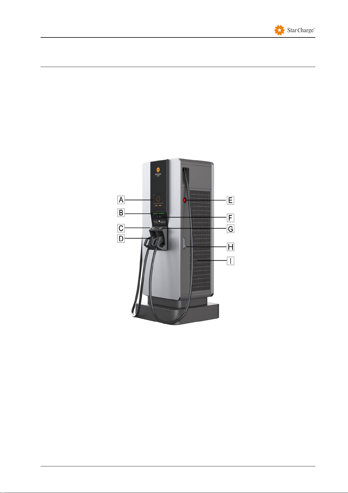
2.1 Product Structure
Figure 2-1 Product diagram
[A]——Touch screen.
[B]——LED status indicator (standby, operation, failure).
[C]——Card swiping area for charging.
[D]——Charging connector slot.
[E]——Emergency stop: press the button to stop the device running when the device is running
abnormally.
[F]——code scanning area for charging.
[G]——Card swiping area for charging.
[H]——Flat lock of the charger.
[I]——Air inlet

Product Overview
Instruction Manual Wanbang Charging Equipment Co.,Ltd 6
The pictures are for reference only.
When charging is completed, insert the connector into slot [D] for safe storage.
2.2 Product Features
2.3 Product Functions
1)Constant current and constant voltage charging function. Suitable for charging EVs with high
voltage lithium battery system.
2)The charger is equipped with CAN bus interface, which is used for communication with the battery
management system(BMS). When the charging mode is set as BMS mode, the charger could
adjust the charging voltage and current in real time according to the control command of the BMS,
and it could stop charging automatically when BMS sends the stop or abnormal command.
Detailed description of product performance
Model
DH-DC1800SG40-B
Dimension
800 mm *726.5 mm *1990 mm
Weight
305kg ( Without modules)
Installation
Floor mounted
Technical
parameters
Input voltage: AC 380V±15%; Input mode: 3P+N+PE
Rated output voltage: DC 750V
Rated output current: DC 240A
Maximum output current: DC 250A/Connector
Output current error: Current ≥30A,error ≤±1%;
Current <30A, error ≤±0.3A
Output voltage error: ≤±0.5%
Power factor: ≥0.98
Total harmonic current: ≤5%(Rated condition, 100% load)
Efficiency: 95%(Rated condition, 100% load)
Protection grade: IP54、IK10
Working temperature: -30℃~+50℃
Protection characteristics: Input over-voltage/under-voltage protection,
Input over-current protection, Output over-voltage/under-voltage
protection, Output over-current protection, Output short circuit protection,
Over temperature protection, Electric leakage protection, Lightning
protection, Insulation detection, Reverse battery protection. etc.
Compliance
NBT 33008.1-2018;GB/T 20234.1-2015;GB/T 20234.3-2015;GB/T
18487.1-2015;NB/T 33001-2018;GB/T 27930-2015

Product Overview
Instruction Manual Wanbang Charging Equipment Co.,Ltd 7
3)Support two charging methods: BMS charging mode and manual charging mode.
The BMS charging method supports "GB / T 27930-2015 Communication protocol between
non-vehicle conductive chargers and battery management systems for electric vehicles" or
user-defined protocols.
The manual charging method can set the output voltage and current via touch screen, which is
suitable for no CAN communication scene.
4)The equipment has protection functions such as Input over-voltage/under-voltage protection,
Output short circuit protection, Output over-voltage protection, Output over-current protection,,
Over temperature protection, Electric leakage protection, Lightning protection, Insulation detection
and Reverse battery protection. An external status light is equipped to display the status of the
charger in real time.
5)Equipped touch screen as HMI.
6)Open, shareable, data service platform and management platform (cloud platform) are available.
7)The Charger is suitable for outdoor, IP54 and IK10.
8)Compatible with OCPP 1.6J communication protocol.
2.4 Technical Characteristics
1)Charging method:
Scan the QR code via APP for charging.
Swipe the RFID card to start charging.
Remote start charging via backend.
2)With docking support for the charger network operation platform, you can quickly navigate and find
chargers through the website, APP, smart remote calling, WeChat, etc., and could know charging
status of chargers through the above methods. In this case, could realize reservation charging
mode, economic charging mode and so on. After charging is completed, users do not need to
swipe their cards, they can pay through Alipay, WeChat, Union Pay, etc..
4)The input power is three-phase five-wire AC380V. The power factor correction is integrated inside
the charger to minimize the pollution of the harmonics on the grid.
5)Using high frequency zero-voltage soft switching technology, the reliability and efficiency is much
higher than normal hard-switching circuit design. The efficiency could up to 95%.
6)With modular design, multiple modules work in parallel with strong fault tolerance. One module
failure does not affect the use of the machine itself. It is convenient to repair and replace individual
modules.
7)Using touch screen as HMI, the working status of each module and the status of the battery can be
displayed in detail. The CAN is used to communicate with BMS in real-time to optimize and
protect the fast charging of the power lithium battery. You can also use the manual charging mode
Product Overview
Instruction Manual Wanbang Charging Equipment Co.,Ltd 8
to set voltage, current, and charging time, which is suitable for applications without CAN
communication.
8)CAN bus is used to realize real-time data exchange with the vehicle to achieve the purpose of
smart charging.
9)Power module features:
Adopt advanced phase shift resonant high frequency soft switch, active PFC technology, which
has high power density, power factor efficiency and low harmonic distortion features.
Simple LED panel design, which let customers know the working status of the module in a timely
and easy-to-understand manner.
Complete protection and alarm functions, including input over/under voltage, output over-voltage,
over temperature, current limit and power limit functions.
Built-in anti-reverse protection, with automatic fail-safe function and support hot plugging.
Support constant power output to avoid power waste.
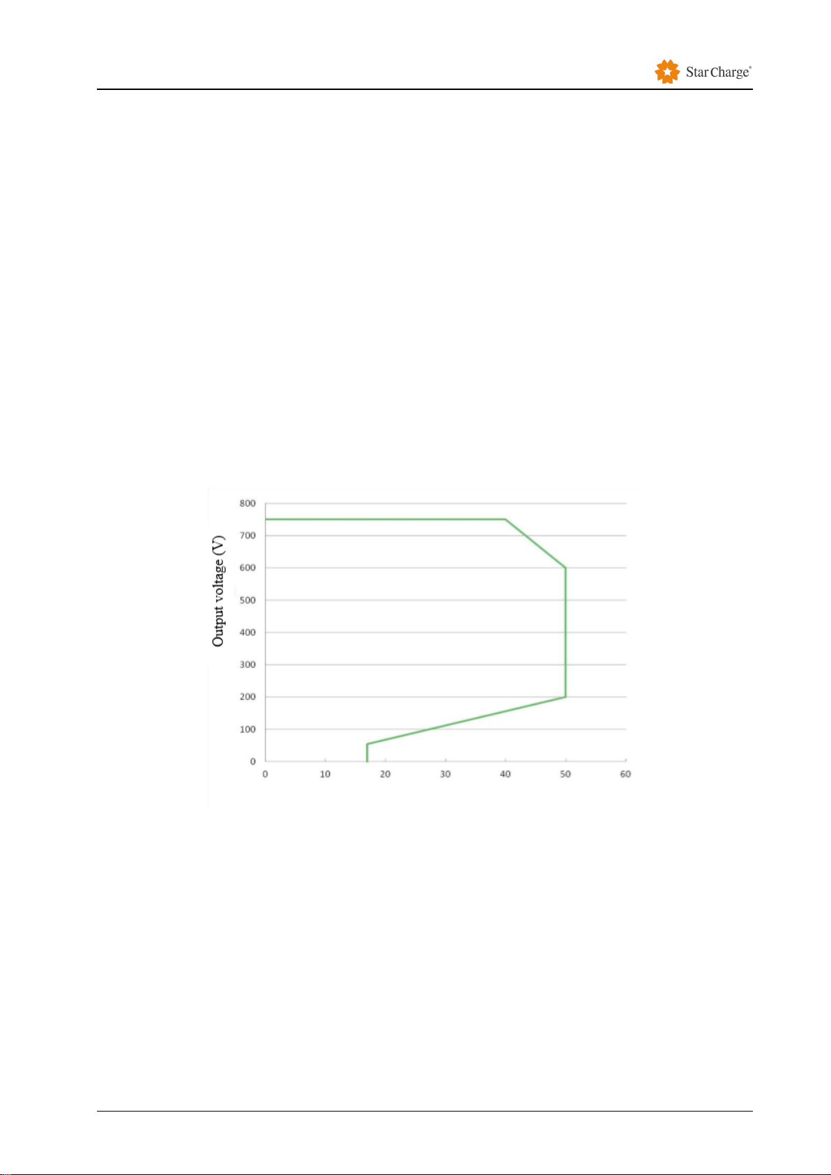
750V&30kW module voltage and current graph:
Figure 2-2 Voltage and current graph of low voltage module(750V&30kW)
Module power and temperature curves:
Voltage & current curve
Output current (A)

Product Overview
Instruction Manual Wanbang Charging Equipment Co.,Ltd 9
Figure 2-3: 750V&30kW Power temperature curve
Parameter
Value
Remark
Output voltage
200~750V
-
Max. output power
30kW
Max. output power of module is 30 kW
under normal condition.
Max. output current
50A
-
Rated current
40A
Rated voltage is 750V
Ambient temp. (℃)
Ambient temp. & power curve
Operation Instruction
Instruction Manual Wanbang Charging Equipment Co.,Ltd 10
3.Operation Instruction
The charger operation has two parts, the charging connection operation and the equipment
operation. To use the product, the user must connect the charger to the vehicle firstly, and then
carry out relevant charging operations through the HMI.
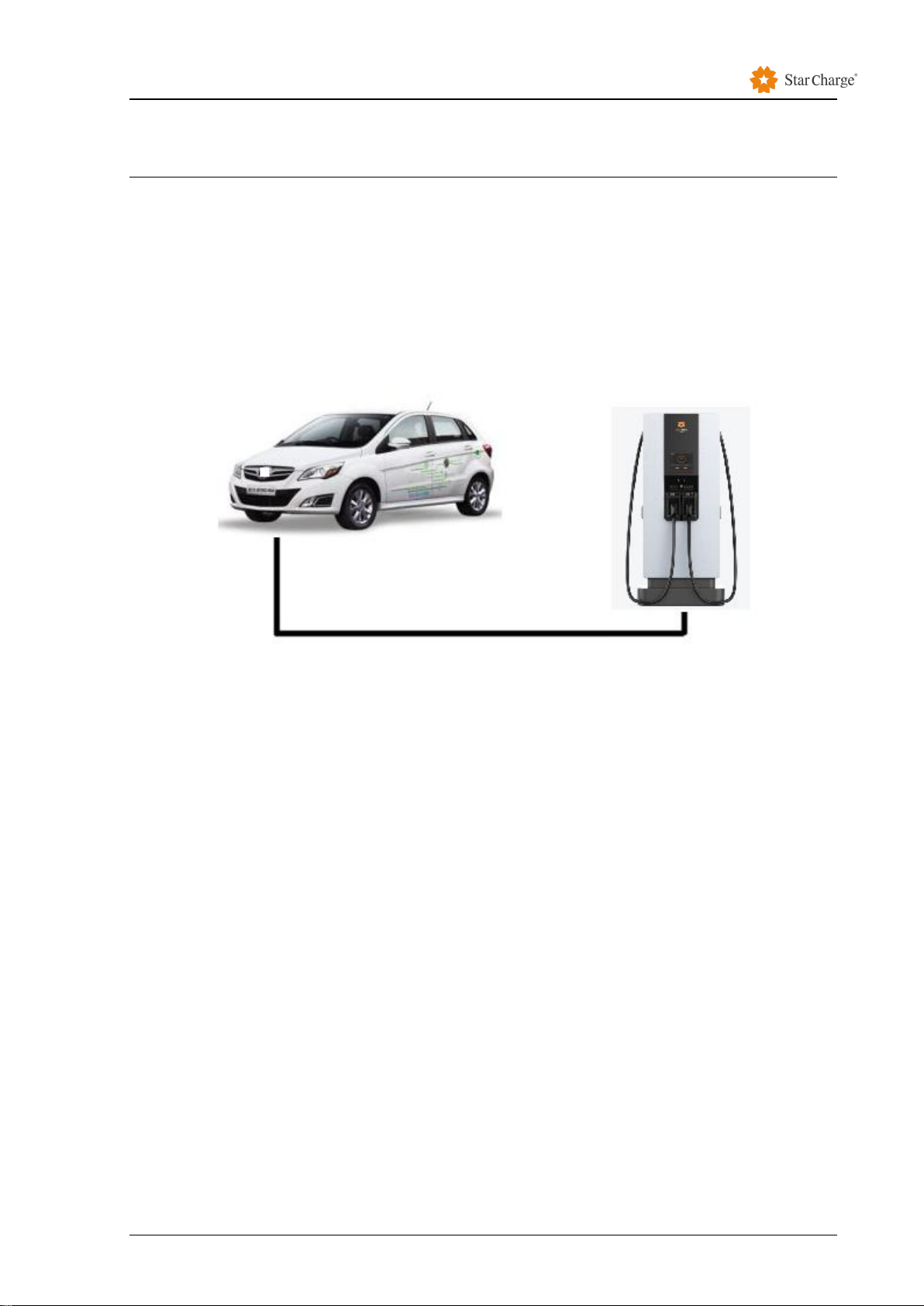
3.1 Charging Connection Operation
Step 1. Confirm that the charger is in normal condition and remove the connector from the holder.
Step 2. Confirm that the vehicle meets the charging conditions and insert the connector into the
corresponding charging port of the vehicle.
Step 3. Confirm that the above connection is intact and start the next step.
3.2 Interface Operation
3.2.1 Swipe the RFID card to charge
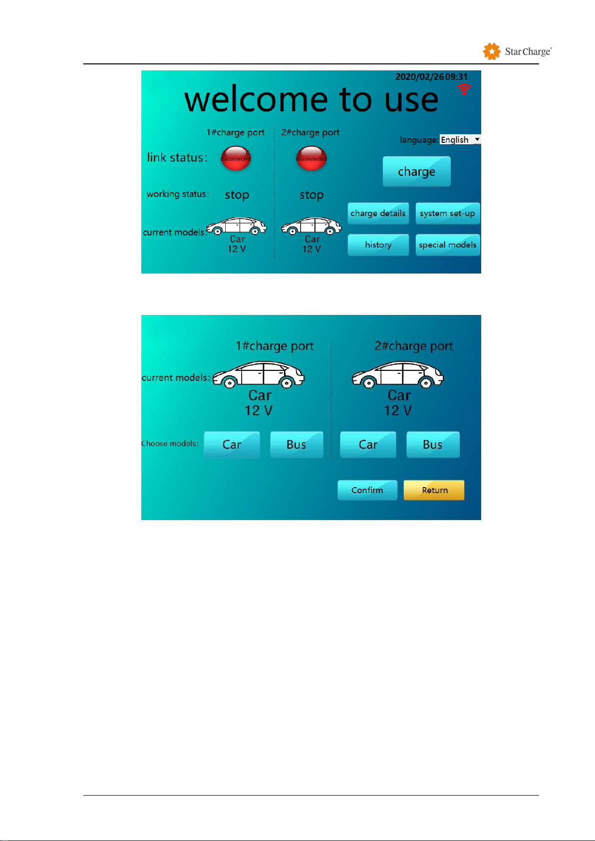
Step 1 Click the screen to turn on the screen and select "special models".
The pictures are for reference only
Operation Instruction
Instruction Manual Wanbang Charging Equipment Co.,Ltd 11
Figure 3-1 Main Interface of Charging (The pictures are for reference only)
Step 2 Enter the model setting interface, and select EV models of charging port.
Figure 3-2 Model settings (The pictures are for reference only)
Step 3 After the setting is completed, click "Confirm" to return to the main interface, click "Charge"
and then select "Scan code".

Operation Instruction
Instruction Manual Wanbang Charging Equipment Co.,Ltd 12
Figure 3-3 Select charging mode (The pictures are for reference only)
Step 4 Click "scan code" to enter QR code interface.
Figure 3-4 Scan interface (The pictures are for reference only)
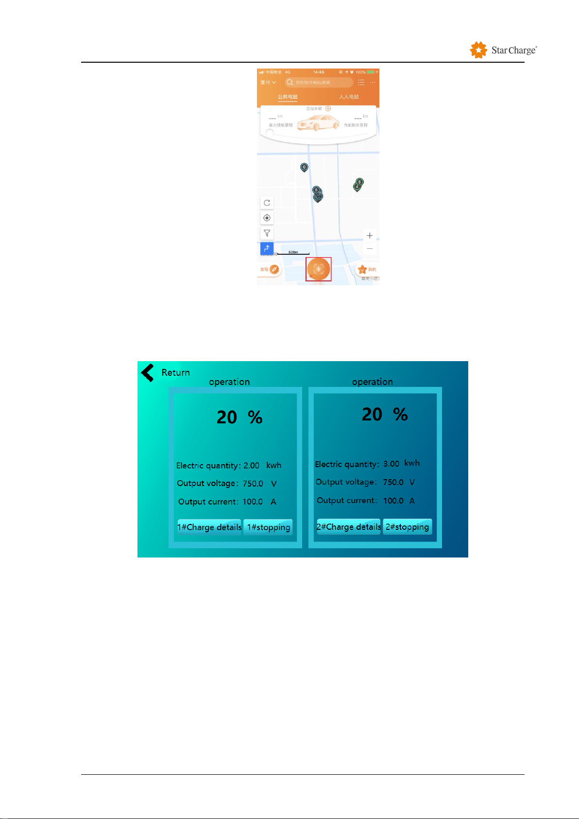
Step 5 OpenApp and click the red button to scan the QR Code on charger’s screen.
Operation Instruction
Instruction Manual Wanbang Charging Equipment Co.,Ltd 13
Figure 3-5 APP interface (Take the star charging app as an example)
Step 6 During the charging process, the charger’s screen displays the interface as shown in
Figure 3-6. The charging state picture here is an example of charging with two connectors at the
same time.
Figure 3-6 Charging status (The pictures are for reference only)
Step 7 After fully charging, click "Back" to return to the main charging interface. You can also stop
charging by clicking the stop button on Star Charge APP or the "Stop Charging" button on the
charger interface.
Step 8 Disconnect the charging connector from the vehicle and return the connector back to the
holder.
3.2.2 Swipe the RFID card to charge
Step 1 Click the screen to turn on the screen and select " special models ".
The pictures are for reference only

Operation Instruction
Instruction Manual Wanbang Charging Equipment Co.,Ltd 14
Figure 3-7 Main Interface of Charging (The pictures are for reference only)
Step 2 Enter the model setting interface, and select EV models of charging port.
Figure 3-8 Model settings (The pictures are for reference only)
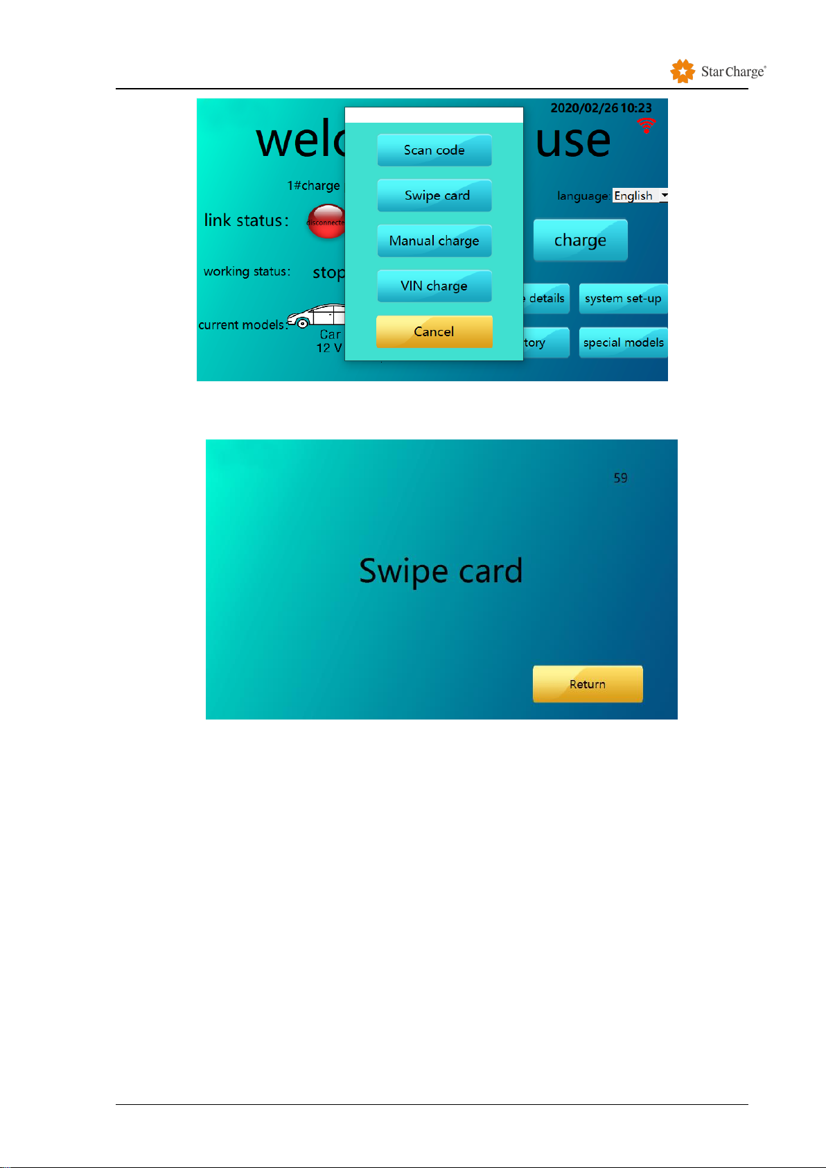
Step 3 After the setting is completed, click "Confirm" to return to the main interface, click "Charge"
and select "Swipe card".
Operation Instruction
Instruction Manual Wanbang Charging Equipment Co.,Ltd 15
Figure 3-9 Select charging mode (The pictures are for reference only)
Step 4 Click" Swipe card " to enter the card swipe interface.
Figure 3-9 Swipe Card Charging (The pictures are for reference only)
Step 5 Place the RFID card on the swiping area to start charging.
Step 6 During the charging process, the charger’s screen displays the interface as shown in
Figure 3-10The charging state picture here is an example of charging with two connectors at
the same time.

Operation Instruction
Instruction Manual Wanbang Charging Equipment Co.,Ltd 16
Figure 3-10 Charging status (The pictures are for reference only)
Step 7 After fully charging, click "Back" to return to the main charging interface. You can also
stop charging by clicking the stop button on Star Charge APP or the "Stop Charging" button on
the charger interface.
Step 8 Disconnect the charging connector from the vehicle and return the connector back to
the holder.

Troubleshooting
Instruction Manual Wanbang Charging Equipment Co.,Ltd 17
4.Troubleshooting
Fault
Possible causes and Solutions
Power LED is off
No power supply.
Check the protection switch od circuit, restart if necessary
Damaged, please contact your service partners.
Input power is normal.
Check the phase sequence to confirm the correct phase
sequence of the inlet cable of the charger.
Unable to start the
charging process
Did not insert the connector into the vehicle properly.
Pull out and plug in again.
Did not execute charging process correctly.
Follow the instructions in the 3.2 Interface Operation process
section.
The connector is dirty or damaged around the security area.
Clean or replace the charging connector.
The vehicle is not fully
charged or the
charging time
increased
Due to extreme high temperature of the vehicle or the charger,
current drops:
Visually check if the plug device is smudgy, worn or
damaged.
If necessary, please contact your service partners.
Due to the external control device (power supply equipment,
PV equipment, or others), the charging cannot be completed.
Fault LED status light
turns yellow.
Fault:
Check all possible causes for failure (*)
Cut off the power supply of the charger, pull out the charging
connector of the vehicle and switch the power supply back
on.
Damage:
Please contact your service partners.
(*) Possible causes for failure(fault status, yellow LED light on):
In principle, the fault should be solved by pulling the charging connector out of the vehicle.
The following reasons may cause the failures to occur:
Module
Fault code
Solutions
DC
part
Insulation has abnormally
stopped during charging
Re-plug the charging connector. If the insulation test
passes before charging, check if there is insulation
abnormality at the car end.
Emergency stop bottom has
been pressed
Check if the emergency stop bottom has been
pressed and if the wiring of the emergency stop is
correct.
The door of the charger opens
and the charging stops.
Check whether the travel switch is normal.
DC meter offline
Check whether the 485 communication lines
between electricity meter and the ac mainboard are
normal.
Output is over/under voltage
Check if the input voltage is normal.

Troubleshooting
Instruction Manual Wanbang Charging Equipment Co.,Ltd 18
Abnormal communication of
power module stops during
charging
Check front - end relay for suction.

Routine Maintenance
Instruction Manual Wanbang Charging Equipment Co.,Ltd 19
5.Routine Maintenance
5.1 Power distribution system
Power on and off steps of the distribution box.
1. Check if the supply voltage is normal.
2. Power on: first turn on the main switch of the distribution box and then the branch circuit switch.
3. Power off: first turn off the branch circuit switch, and then turn off the main switch of the
distribution box.
5.2 Wiring System
5.2.1 Wire slot
Weekly routine inspection: check whether the wire groove is fixed firmly, the cover plate is
completed and if the wire in the slot is exposed or not.
Monthly routine inspection: check whether the wire groove is fixed firmly, and if the cover
plate is completed and sealed.
Annual routine inspection: check whether the wire groove is fixed firmly, the cover plate is
completed and tight, the joint is loose or not and if there is distortion and deformation or if the
fastener is loosened, corroded or rusted.
5.2.2 Cable
Weekly routine inspection: check cable for heating and breakage.
Monthly routine inspection: check the cable for heating, breakage and if it is pulled forcibly
or fixed securely.
Annual routine inspection: check whether the cable is connected closely to the switch, if
the grounding is reliable, if the cable is hot or damaged and whether the insulation resistance
of the cable is in accordance with the regulations. The sealing measures of the cable into the
box should be intact and tightly sealed.
5.3 Circuit Components
5.3.1 Components
Weekly routine inspection: the emergency stop button is working normally. After pressing
the emergency stop button and that it is confirmed the control circuit is disconnected, check
whether all operation indicator lights and buzzers are working normally and if the charging
connector's fixed clasp is damaged or the connection is abnormal.
Table of contents
Other StarCharge Batteries Charger manuals


