ELCOS DIM-807/00 Instruction Manual

IRRIGATION CLOSE-COUPLED PUMP PROTECTION DEVICE
TYPE
THE CLOSE-COUPLED PUMP IS STOPPED
(VIA ELECTROMAGNET OR SOLENOID) IN CASES OF ANOMALY FOR:
• LOW COOLING LIQUID LIVEL
• INEFFICIENT BATTERY CHARGE ALTERNATOR (BELT BREAKAGE)
• LOW OIL PRESSURE
• OVERHEATING
• FUEL RESERVE (WITHOUT STOPPING ENGINE)
• INSUFFICIENT WATER PUMP PRESSURE
OIL AND BATTERY INDICATORS INTEGRATED INTO THE DEVICE
GB DIM-807/00 /4 1
DIM-807/00
INSTRUCTION AND USER MANUAL
®
PARMA ITALY
Fax +39 0521/270218
Tel. +39 0521/772021

This surveys the functioning of the close-coupled pump and stops it if there are anomalies in the parts controlled
by probes.
It has been designed to be installed in cavities in dashboards, electric panels, etc.
NOTICES
Warning:
adhere closely to the following advice
- Always install under other equipment which produces or spreads heat.
- Always follow the Circuit Diagram on pages 6-7 when making connections.
- Check that the line loading and the consumption of the connected equipment are compatible with the
technical characteristics on page 12.
- All technical interventions must be performed with the engine stationary and terminal 50 of the
starter motor disconnected.
- Never use a battery charger for the emergency start-up, this could damage the equipment.
- To protect the safety of persons and the equipment, before connecting an external battery charger,
disconnect the electrical plant terminals from the battery poles.
NOTE: THE HOLE IN THE CASING USED TO INSTALL THE PROTECTION DEVICE COULD INFLUENCE THE
LEVEL OF PROTECTION OF BOTH. STEPS MUST BE TAKEN TO MAINTAIN THE ORIGINAL LEVEL
OF PROTECTION.
THIS DEVICE IS NOT SUITABLE FOR OPERATING IN THE FOLLOWING CONDITIONS:
- Where the environmental temperature is outside the limits indicated in the .
- Where there are high levels or heat from radiation caused by the sun, ovens or the like.
- Where there is the risk of fire or explosions.
- Where the device can receive strong vibrations or knocks.
Technical Data on page 12
The following maintenance operations should be performed every week:
- check that the indicators function;
- check the batteries;
- check that the conductors are tight, check the condition of the terminals.
CONDUCTION AND MAINTENANCE
ELECTROMAGNETIC COMPATIBILITY
This protection device functions correctly only if inserted in plants which conform with the CE marking standards;
it meets the exemption requirements of the standard EN50082-1 but it cannot be excluded that malfunctions
could occur in extreme cases due to particular situations.
The installer has the task of checking that the disturbance levels are within the requirements of the standards.
YOUR ELECTRICAL TECHNICIAN CAN ASK US ANYTHING ABOUT THIS PROTECTION
DEVICE BY TELEPHONING ONE OF OUR TECHNICIANS
UNLESS WE MAKE A WRITTEN DECLARATION STATING THE CONTRARY, THIS PROTECTION DEVICE IS
NOT SUITABLE FOR USE AS A CRITICAL COMPONENT IN EQUIPMENT OR PLANTS RESPONSIBLE FOR
KEEPING PERSONS OR OTHER LIVING BEINGS ALIVE
2GB DIM-807/00 /4
IRRIGATION CLOSE-COUPLED PUMP PROTECTION DEVICE
TYPE DIM-807/00
GB DIM-807/00 /4 3
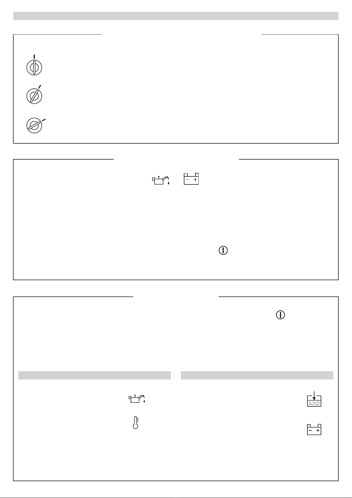
FUNCTIONING
IGNITION KEY
TWIN FUNCTIONS INDICATORS
ENGINE PROTECTIONS
- REST
- MANUAL STOP
- RESET PROTECTION
- DEVICE SUPPLY
- START CLOSE-COUPLED PUMP
0
(AUT.)
(START)
These are on when the key is turned to "AUT". They switch off when the engine is running and the
oil pressure and battery recharger are regular.
- OIL AND BATTERY INDICATORS
- ANOMALY INDICATORS
These are enabled after the ENGINE PROTECTIONS ACTIVE indicator switches on, and they
switch on when the relevant anomaly is detected.
The engine protections are enabled when the ENGINE PROTECTIONS ACTIVE indicator is
on (20 seconds after turning the key to "AUT" or, in any case 20 seconds after the end of the start
impulse).
The interventions of the protection probes (mounted on the engine), shown by the relevant visual
indicators, stop the engine and can be divided into two groups:
After a 3-second delay for:Immediately for:
- OIL PRESSURE SWITCH
- OVERHEATING THERMOSTAT
- COOLING LIQUID LEVEL PROBE
- BATTERY CHARGE ALTERNATOR
(ALTERNATOR BELT BREAKAGE)
(MOUNTED EXTERNALLY)
4GB DIM-807/00 /4
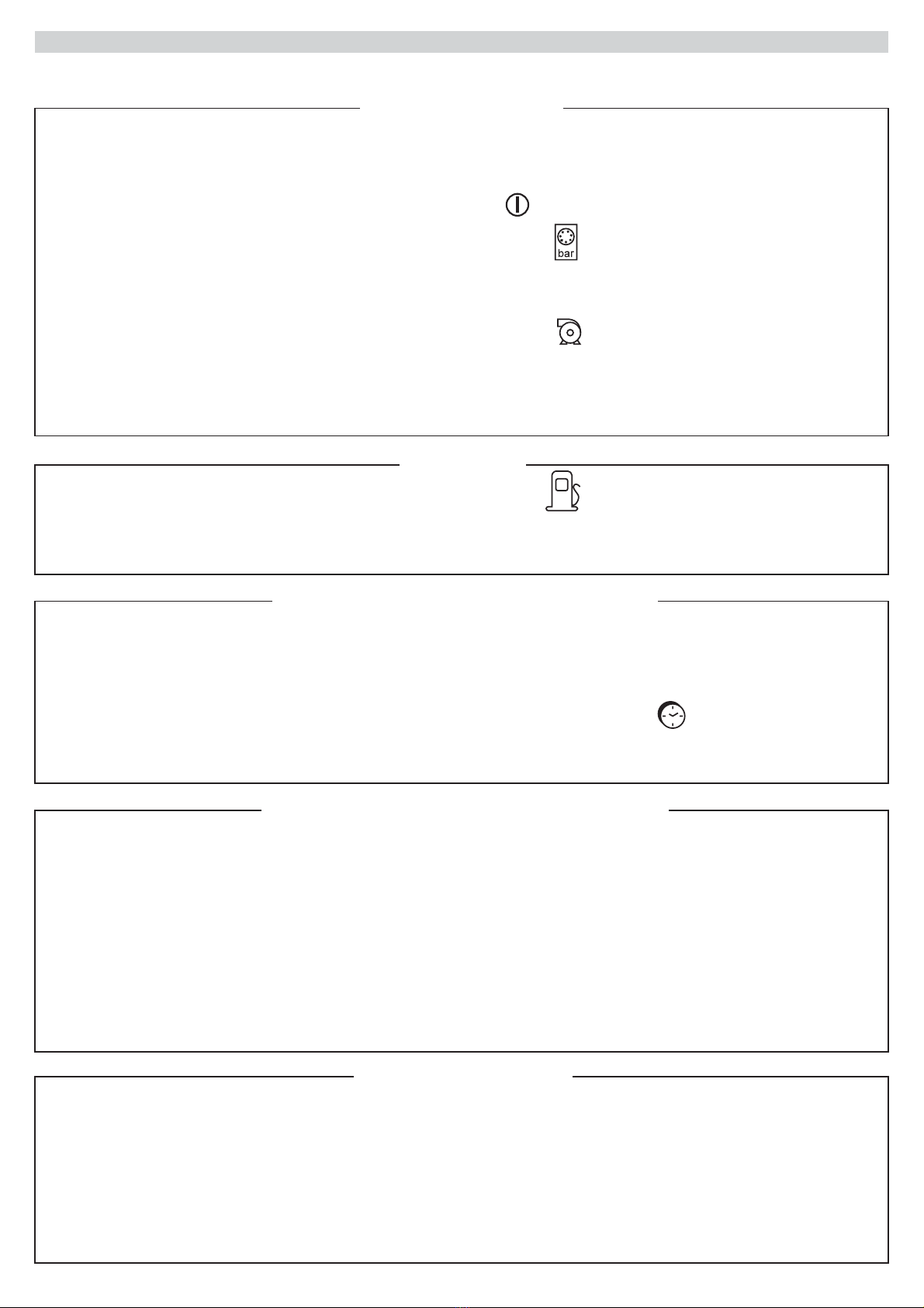
FUNCTIONING
PUMP PROTECTION
STOPPING THE CLOSE-COUPLED PUMP
TIMER (TO BE MOUNTED EXTERNALLY)
MAIN ALARM
This is obtained in three ways:
y turning the ignition key to zero
ecause of protections intervention
ecause of timer intervention.
The protection device uses two different types of stoppage:
- activating the ELECTROMAGNET which pulled the STOP lever for 20 seconds
- disconnecting the supply to the SOLENOID which closes the gasoline passage.
-b
-b
-b
This can be obtained by mounting a visual and/or acoustic indicator externally connected to the
relevant output.
This is continuously activated if the protections or fuel reserve alarm intervene.
RESET: This is obtained by turning the ignition key to zero.
The pump protection is enabled (after 3 minutes (adjustable), the time needed for the water to be
pressurized) when the PUMP PROTECTION ACTIVE lights up.
When the pressure is regular, the relevant indicator lights up.
The intervention of the protection (5 seconds after the lowering of the pressure as detected by the
water pump pressure switch) stops the engine. This is memorized and is shown by the
INSUFFICIENT WATER PUMP PRESSURE visual indicator.
RESET: This is obtained by turning the ignition key to zero.
Connect the timer to the relevant terminal, if the working time of the close-coupled pump is to be set.
Stopping occurs after this time period and the relevant indicator lights up.
Enabled when the key is turned to "AUT", without stopping the engine.
(FUEL RESERVE)
ALARM

GB DIM-807/00 /4 5
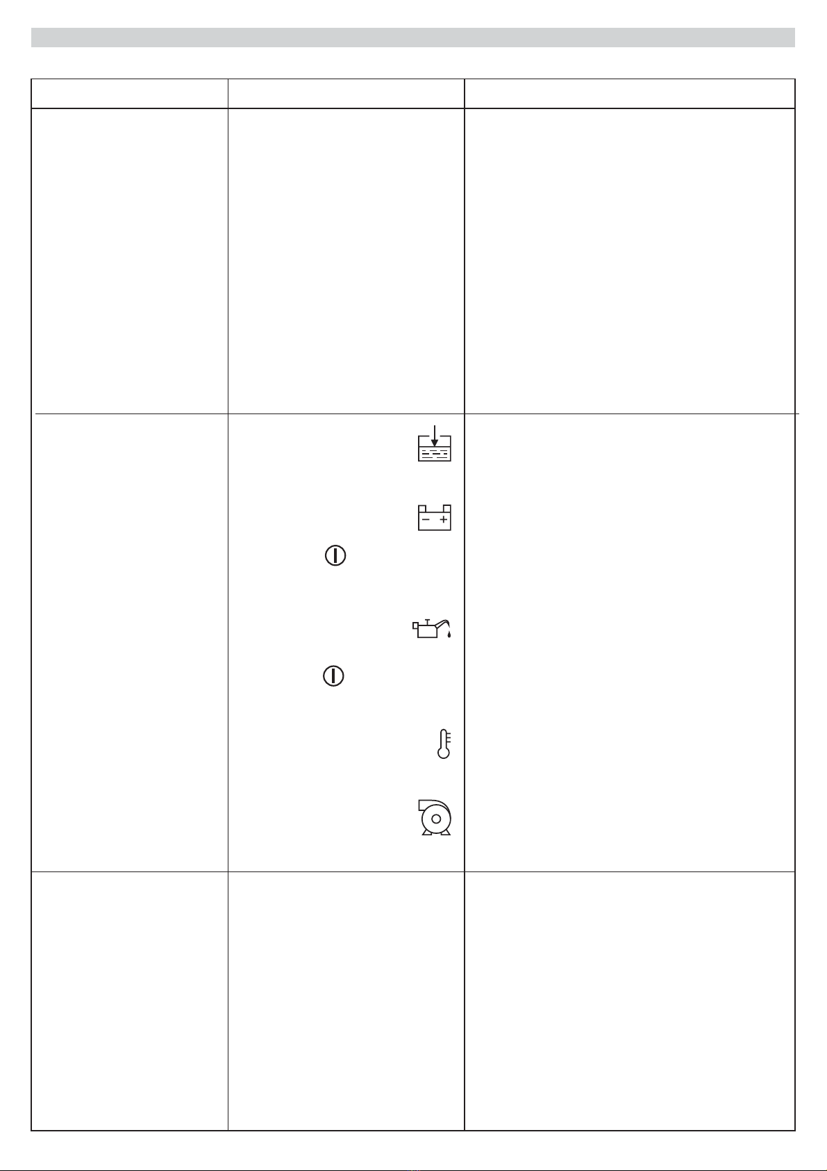
ENGINE PROBES TEST
(WITH PROBES DISCONNECTED)
NOTE: WHEN THE TEST HAS BEEN COMPLETED RECONNECT THE PROBES
FUNCTION PERFORMED TEST
LOW COOLING
LIQUID LEVEL
RECHARGE
ALTERNATOR
(BELT BREAKAGE)
LOW OIL
PRESSURE
OVERHEATING
FUEL RESERVE
INSUFFICIENT
WATER PUMP
PRESSURE
TIMED
STOP
RADIATOR
PROBE
W
RESISTANCE BETWEEN
PROBE AND EARTH:
- WITH LIQUID MAX. 6000
- WITHOUT LIQUID, ABOVE 6000
W
W
ENGINE
STATIONARY
ENGINE
STATIONARY
ENGINE RUNNING
WITH REGULAR
BELT
ENGINE RUNNING
WITH REGULAR
PRESSURE
ENGINE WITH
NORMAL
TEMPERATURE
SUFFICIENT FUEL
TIMER AT
ZERO HORAS
CLOSE-COUPLED
PUMP RUNNING
WITH REGULAR
WATER PRESSURE
CLOSE-COUPLED
PUMP RUNNING
WITH SUFFICIENT
WATER PRESSURE
CLOSE-COUPLED
PUMP STATIONARY
ENGINE RUNNING
WITH BROKEN
BELT
ENGINE RUNNING
WITH INSUFFI-
CIENT PRESSURE
ENGINE
OVERHEATING
INSUFFICIENT
FUEL
TIMER WITH
SET HOURS
NORMALLY THE
RELEVANT
TERMINAL OF THE
BATTERY CHARGE
ALTERNATOR IS
NEGATIVE WITH
THE ENGINE
STATIONARY
NORMALLY THE
TERMINAL OF THE
OIL PRESSURE
SWITCH IS
NEGATIVE WITH
THE ENGINE
STATIONARY
NORMALLY THE
TERMINAL OF THE
THERMOSTAT IS
NEGATIVE WHEN
THE ENGINE IS
TOO HOT
NORMALLY THE W
TERMINAL OF THE
FLOAT IS
NEGATIVE WHEN
THE FUEL IS
RUNNING OUT
NORMALLY THE
TIMER TERMINAL
(INDICATED IN THE
FIGURE ALONGSIDE)
IS NEGATIVE
WHEN THE HOURS
ARE SET
NORMALLY THE
PURPLE WIRE OF
THE WATER
PRESSURE SWITCH
IS NEGATIVE
WHEN THE PUMP
IS STATIONARY
D+
B+
GRGB LC
R
LE
+~~
YELLOW
YELLOW
RED
PERMANENT
MAGNET
ALTERNATOR
PRE-EXCITATION
ALTERNATOR
OIL PRESSURE
SWITCH
THERMOSTAT
FLOAT
TIMER
PRESSURE
SWITCH
W
3W
3W
3W
3W
PURPLE HIRE
0
1
2
3
4
5
6
7
8
9
10
11
12
GREY
**

6GB DIM-807/00 /4
CIRCUIT
B+
D+
1
2/7
3
416
15
47
41
40
28
30
50
30
15/54
50
W
157
3W
MAX
(BELT BREAKAGE)
12356782930
33
31
34
37
35
39 40
39 40
DIM-807/00
PUMP
PROTECTION
ENABLING
3'13'
0
1
2
3
4
5
6
7
8
9
10
11
12
FUSE
5A
FUSE
5A
REGULATION
WATER PUMP
PRESSURE
WARNING
WARNING:
SET AT 2 BAR BELOW
THE WORKING
PRESSURE.
IT IS NOT NECESSARY TO
ADJUST THE PRESSURE
SWITCH AGAIN IF THE
WORKING PRESSURE
REMAINS UNCHANGED.
IF THE FUNCTION
IS NOT USED:
33
• LOW COOLING
LIQUID LEVEL
CONNECTCONNECT TER-
MIINAL33 TO EARTH
(TO BE MOUNTED
EXTERNALLY)
14
30
87
86
85
30
UNCONNECTABLE

GB DIM-807/00 /4 7
DIAGRAM
(1) IGNITION KEY
(2/7) ELECTROMAGNET OR
SOLENOID
(3) OIL PRESSURE SWITCH
(4) THERMOSTAT
(15) WATER PUMP PRESSURE SWITCH
(16) FUEL FLOAT
(47) TIMER
(155) RADIATOR LIQUID LEVEL PROBE
(157) INDICATOR (MAIN ALARM)
(30) 3A 200V DIODE
The system is arranged to command
the stopping with SOLENOID.
For ELECTROMAGNET stopping,
connect terminals 39 and 40.
(14) CHARGE CONTROL LAMP
(27) ALTERNATOR REGULATOR
(28) PRE-EXCITATION CHARGE
ALTERNATOR
(40) STARTER MOTOR
(41) BATTERY
AVAILABLE ON REQUEST
ACCESSORIES
STOP SYSTEMS SET UP
MOUNTED ON ENGINE
155
ROD
ELECTRODE
COOLING LIQUID LEVEL PROBE
FOR RADIATORS WITH
PLASTIC EXPANSION TANKS
FOR RADIATORS WITH
METAL EXPANSION TANKS
155
SCREW
ELECTRODES
DRIVE
EXCITATION
STOP
EXCITATION
SOLENOID
for closing
diesel
ELECTROMAGNET
for pulling
STOP lever
39 40

8GB DIM-807/00 /4
DEVICE TEST
TROUBLE SHOOTINGS
(SIMULATION)
FUNCTION PERFORMED
TYPE OF PROBLEM
INTERVENTION SIMULATION
(WITH INDICATOR ON
PROTECTIONS ARE ACTIVE)
PROBABLE CAUSES
FUNCTIONS INTERVENTION
(STOP, GENERAL ALARM
AND VISUAL INDICATOR ON)
REMEDIAL INTERVENTIONS
LOW COOLING
LIQUID LEVEL
THE STARTER MOTOR
FUNCTIONS BUT THE
ENGINE DOES NOT
START
RECHARGE
ALTERNATOR
(BELT BREAKAGE)
LOW OIL
PRESSURE
OVERHEATING
FUEL RESERVE
INSUFFICIENT
WATER PUMP
PRESSURE
TIMED STOP
DISCONNECT THE TERMINAL
FROM THE ROD MOUNTED
ON THE RADIATOR
- Lack of fuel
- Fuel supply circuit defect
- Low temperature
- Fill the tank
- Check that the stop system (solenoid or
electromagnet) functions
- Consult the engine instruction manual
- Check that the preheating functions
AFTER 3 SECONDS
AFTER 3 SECONDS
IMMEDIATELY
IMMEDIATELY
AFTER 3 SECONDS
the relevant indicator will light upe
without stopping the engine
AFTER 5 SECONDS
IMMEDIATELY
DISCONNECT THE WIRE FROM
TERMINAL [8] OF THE DEVICE AND
CONNECT TERMINAL [8] TO EARTH
DISCONNECT THE WIRE FROM THE
OIL PRESSURE SWITCH TERMINAL
AND CONNECT IT TO EARTH
DISCONNECT THE WIRE FROM THE
THERMOSTAT TERMINAL
AND CONNECT IT TO EARTH
DISCONNECT THE WIRE FROM THE
W TERMINAL OF THE FLOAT
AND CONNECT IT TO EARTH
SIMULATION OF INTERVENTION (WITH
PUMP PROTECTION ACTIVE
INDICATOR ON). DISCONNECT THE
PURPLE WIRE FROM THE TERMINAL
[34] OF THE DEVICE AND CONNECT
THE TERMINAL [34] TO EARTH
DISCONNECT THE WIRE FROM
TERMINAL [35] OF THE DEVICE AND
CONNECT THE TERMINAL [35] TO
EARTH, DISCONNECT AND THEN
RECONNECT IT
NOTE
WHEN THE SIMULATION HAS BEEN COMPLETED ENSURE THAT ALL OF THE CONNECTIONS
ARE RETURNED TO THEIR ORIGINAL POSITIONS
3535 35
- The low cooling liquid
level indicator lights up
- The belt breakage
indicator lights up after
the PROTECTIONS
ACTIVE indicator
lights up
- The low oil pressure
indicator lights up after
the PROTECTIONS
ACTIVE indicator
lights up
- The overheating
indicator lights up
- The insufficient water
pump pressure lights up
- Flat battery
- Starter motor is
defective
- An anomaly indicator is
on
- Defective ignition key
GB DIM-807/00 /4 9
TROUBLE SHOOTING
TYPE OF PROBLEM PROBABLE CAUSES REMEDIAL INTERVENTIONS
ENGINE STOPS FOR
ANOMALY
THE STARTER MOTOR
DOES NOT FUNCTIONS
ENGINE DOES NOT
STOP UNDER ANY
CONDITIONS
- Stop system
(electromagnet or
solenoid) does not function
- Defective engine probes
- Defective device
- Check the level of the cooling liquid
- Check the condition of the alternator belt
- Check the engine oil level
- Check the engine cooling system
- Check that the handle of the water pump
pressure switch has been set at 2 bars
below the plant pressure
- Recharge the battery and clean the
connection terminals
- Check that there are +12V or + 24V on
terminal 50 of the starter motor during the
start phase.
Check and, if necessary, replace
the starter relay.
- See ENGINE STOPS FOR ANOMALY
- Replace the ignition key and check
- Check the correct mechanical or electrical
functioning of the stop system. If the
problem persists, check the stop
servo-relay.
- Test the probes (see ENGINE PROBES
TEST on page 5) and if necessary replace
them.
- Check that during the stop phase there is
voltage on terminal (5) (see STOP on page
4), simulate the function (see DEVICE
TEST on page 8 and if necessary replace
the device (*)

10 GB DIM-807/00 /4
- Low cooling liquid level
indicator on
- The belt breakage
indicator lights up after
the PROTECTIONS
ACTIVE indicator
lights up
- The low oil pressure
indicator lights up after
the PROTECTIONS
ACTIVE indicator
lights up
- The overheating indicator
lights up
- Insufficient water pump
pressure indicator on
- Defective device
- Defective timer
- Defective device
TYPE OF PROBLEM PROBABLE CAUSES REMEDIAL INTERVENTIONS
CLOSE-COUPLED PUMP
STOPS FOR ANOMALY
THOUGH ALL APPEARS
TO BE REGULAR
CLOSE-COUPLED PUMP
STOP ANOMALY WITH
INDICATOR ON
- Test the probe, clean it and, if necessary,
replace it
- Check the function of the charge alternator
- Test and, if necessary, replace the oil
pressure switch
- Test and, if necessary, replace
the thermostat
- Test and, if necessary, replace the water
pump pressure switch
- Simulate the functioning of the device for
the anomaly indicated (see DEVICE TEST
on page 8) and if necessary replace it (*)
- Test the timer and, if necessary , replace it
- Simulate the timed stop function (see
DEVICE TEST on page 8) and if necessary
replace it (*)
TROUBLE SHOOTING
[*] ASSISTANCE REQUEST
Turn the key to zero to reset the functioning
Our assistance service is always at your disposal. When you contact us, you should be ready to provide the following
information:
- The type of equipment installed
- The problem encountered
- The state of the dashboard indicators when the problem arose
- Any previous corrective action taken

GB DIM-807/00 /4
11
ACCESSORIES AVAILABLE ON REQUEST
FOR OHTER ACCESSORIES AVAILABLE ON REQUEST SEE PAGE 7
RADIATOR LIQUID LEVEL PROBE
ROD ELECTRODE
(COMPLETE WITHI:
RIVET CONNECTION,
BOLT, NUT, WASHER,
GASKET AND FEMALE
CONNECTOR)
SCREW ELECTRODES
(COMPLETE WITH:
LUGS)
type AST-015/00
type E 25
code 24.10.12
code 19.01.15
ACCESSORIES DATA FOR ORDERING
MOBILE SOCKETS
type PMO-134/00 code 80.42.34
type PMO-136/00 code 80.42.36
ENGINE PROTECTIONS DEVICE
type code
type code
DIM-807/00 12 V 03.02.03
DIM-807/00 24 V 03.02.04
12 GB DIM-807/00 /4
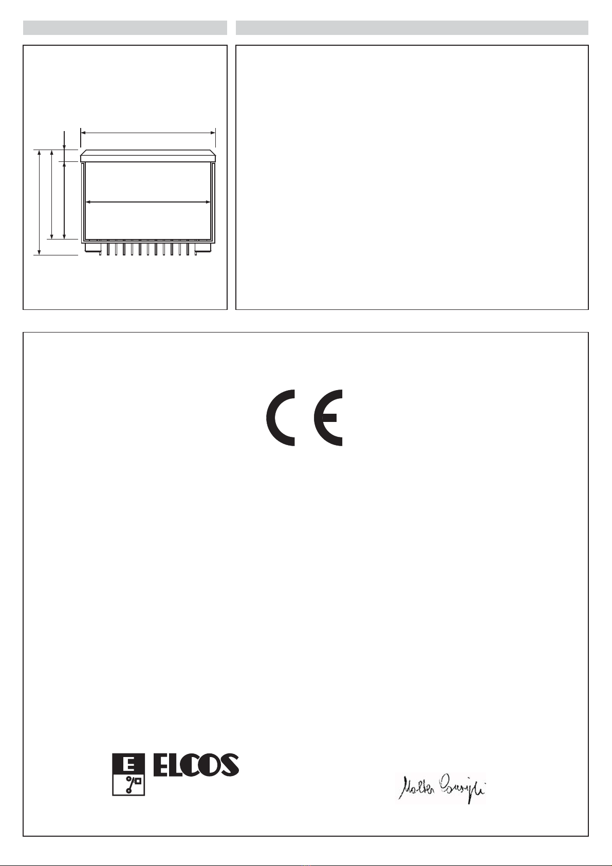
DIMENSIONS TECHNICAL DATA
Ø86
Ø80
67
57
49.5 7.5
- BATTERY SUPPLY 12 VDC (MAX 16 VDC)
VOLTAGE or 24 VDC (MAX 32 VDC)
- CIRCUIT LOADING WITH KEY
TURNED TO ZERO 8 mA
- MAXIMUM LOAD ON OUTPUT [5] 3 A
(STOP)
- MAXIMUM LOAD ON OUTPUT [7] 3 W
(GENERAL ALARM)
- TEMPERATURE RANGE -10 ÷ +60 °C
- TERMINAL BOARD FASTON 6.35 × 0.8
- DEGREE OF PROTECTION
FRONT / REAR IP 65 / IP 00
- 460 g
WEIGHT
CONFORMITY DECLARATION
The company Elcos s.r.l. assumes full responsibility for declaring that the equipment:
when used in the ways and for the purposes described in the enclosed
documents is in conformity with the following directive:
89/336/CEE
93/68/CEE
concerning electromagnetic compatibility
modified by the directive
being manufactured and functioning in accordance with the harmonized
standards:
EN 50081-1, EN 50082-1, EN 60529
type: DIM-807/00
®
Via Naviglio Alto, 24/a
43100 PARMA ITALIA
S.r.l.
Fax +39 0521/270218
Tel. +39 0521/772021
Walter Consigli
Parma, 18/6/1999
President
Table of contents
Other ELCOS Protection Device manuals


Popular Protection Device manuals by other brands


Petzl
Petzl trac manual

FireFlex Systems Inc.
FireFlex Systems Inc. N2 BLAST Owner's operation & maintenance manual

Eaton
Eaton ARCON 2.0 Series Operation and configuration instructions. Technical description

Auerswald
Auerswald SG-100 instructions

Centurion
Centurion Contour Carrier manual

ABB
ABB RELION REL670 Installation and commissioning manual