Eldes ESR100 User manual

ESR100

2
2EN ESR100
Contents
1. QUICKSTART GUIDE.................................................................................................................................................................3
2. TOOLBAR..................................................................................................................................................................................4
3. ADMIN ......................................................................................................................................................................................5
4. LOWER TOOLBAR.....................................................................................................................................................................5
5. DEVICES ...................................................................................................................................................................................6
6. CLIP DB.....................................................................................................................................................................................7
7. MONITORING ...........................................................................................................................................................................8
8. GSM ..........................................................................................................................................................................................9
9. SETTINGS...............................................................................................................................................................................10

3
3EN
ESR100
1. QUICKSTART GUIDE
NOTE: It is recommended to use the DHCP connection.
Locate the two ports at the back of the device
ETH1 port - DHCP
ETH2 port - Fixed
DC IN
12V
DHCP
ETH 1
FIXED
ETH 2
1
Plug in the cable into ETH1 port.
The device should automatically set up the connection
After connecting the cable, open your browser and type http:/esr100 in the address bar and press Enter.
2
You should be redirected to the Login window, where you can enter your username and password and start using the device.
3
If you have failed to log in, plug in the cable into ETH2 port.
DC IN
12V
DHCP
ETH 1
FIXED
ETH 2
4
4
4EN ESR100
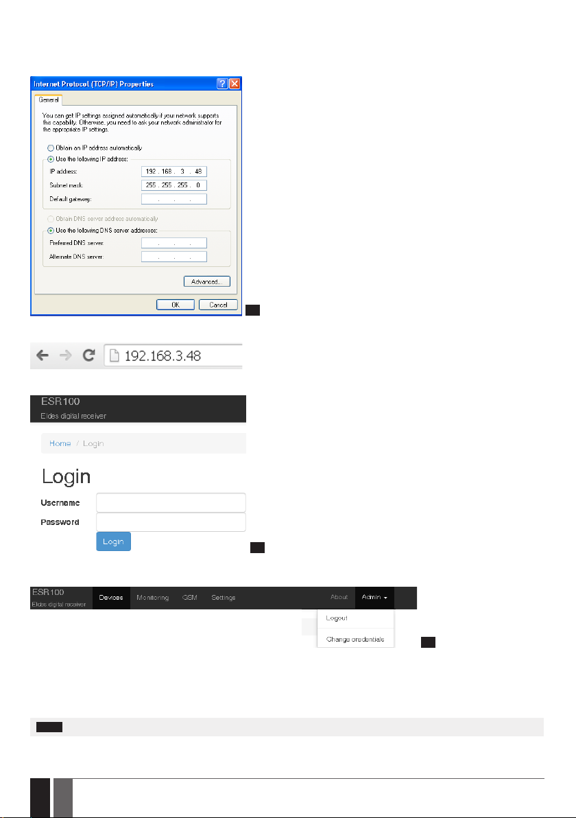
The port has a xed IP address.
In order for the device to start working, you will need to enter the following I.P. address - 192.168.3.48 - in Internet protocol properties.
You can access these properties the following way:
Network places →Network connections →Local area connection properties →Internet protocol properties.
5
After entering the following I.P. and pressing OK, enter the I.P. address in the address bar of your browser and pres enter:
You should be redirected to the Login window, where you can enter your username and password and start using the device.
6
2.TOOLBAR
7
Devices - opens the Devices section, where you can review information about wireless devices and adjust their settings.
Monitoring - opens the Monitoring station window, where you can manage monitoring station settings.
GSM - opens the GSM settings window, where you can view the modem status and change CSD settings.
Settings - this section provides receiver control options and LAN conguration settings.
About - opens the help le.
NOTE: The upper toolbar is xed at the top of the window and will appear in all sections

5
5EN
ESR100
3.ADMIN
8
Admin - opens up the drop-down list, which allows you to logout or change admin credentials, like the username and password.
9
To change current login credentials you have to enter your current username and password in specied elds. Then you need to enter
your new username and password, and click Change button afterwards.
4.LOWER TOOLBAR
The lower toolbar provides you with information about the modem and receiver status, as well as information about system memory.
10
Modem - Shows the modem status.
Values:
• Online
• Oine
Receiver - Shows the receiver status.
Values:
• Running
• Not running
System load - Species how much system resources are currently used.
Memory usage % - Species current memory usage of the system.
NOTE: The lower toolbar is xed at the bottom of the window and appears in all sections.

6
6EN ESR100
5.DEVICES
Devices section displays information about wireless devices, which are currently being monitored.
11
Unit ID - Identication number of a certain wireless device.
12
NOTE: When you put your mouse over a certain unit ID, a box will pop up, indicating the IMEI number of the device.
Account - Identication number of the account, assigned to a wireless device, which is sent to the monitoring station during data
transmission.
Last Channel - Data transmission channel used to receive the last event.
Avaliable channels:
• TCP
• UDP
• SMS
• CSD
Last Channel Value - Value, depending on the channel used to receive the last event.
13
If the Last Channel used for data transmission was TCP/UDP, the value will be will be specied as an IP address.
If the Last Channel used for data transmission was SMS/CSD, the value will be will be specied as a telephone number.
NOTE: If the CLIP DB parameter is turned ON and SMS/CSD channel is used for data transmission, the Last Channel Value eld will
display a username assigned to the telephone number in CLIP DB database. For more information see chapter 6. CLIP DB.
FW Version – Current rmware version of connected devices.
GSM Level (dB.) - GSM signal strength level.
14

7
7EN
ESR100
Last Event Time - time of the last event received from a certain wireless device by the monitoring station.
15
NOTE: When you put your mouse over a certain event time, a box will pop up, indicating the date and time last update of the information.
Timeout 1... 3 - If there were no messages from the device during the set time value in the Timeout 1,2 and 3 a notication is sent to the
monitoring station after each timeout.
Monitoring station - Shows which monitoring station received a certain event and what data transferring type was used.
Serial - Serial port
USB1 - USB port
USB2 - USB port
USB3 - USB port
USB4 - USB port
6.CLIP DB
ATTENTION: Numbers which are NOT added to the CLIB DB database will NOT be able to communicate with the monitoring station.
16
CLIP DB section allows you to turn on CLIP DB function. When it is turned on, the system will receive incoming alerts and event
notications Only from the numbers located in the list.
Each time CLIP DB function is turned ON or OFF a verication window pops up, asking you to conrm your actions.
Add New Number - Allows to add a new number to the CLIP DB section. Pushing this button takes you to a number adding section,
where you have to enter your number and name.
17
After entering the required information in the appropriate elds, click the Add button.

8
8EN ESR100
18
Total x items - shows the total number of items in the database, where xis the exact number of items.
Numbers:
Name - name of a user in the database.
Number - telephone number of the user in the database.
Updated - last time the user information was added or updated.
Additional options:
There are three buttons next to each entry in the database.
1 2 3
19
1. View button - show more detailed information about the certain user.
2. Update button - change information of an existing user.
2. Delete button - delete existing user from the database.
20
If the CLIP DB parameter is turned ON and SMS/CSD channel is used for data transmission, the DEVICES →Last Channel Value eld will
display a username assigned to the telephone number in CLIP DB database.
7. MONITORING
Monitoring section provides access to monitoring station settings.
21
Name - name of the channel, receiving data from the monitoring station.
Baudrate - speed of COM port settings.
Heartbeat - function, allowing to check the signal between the monitoring station and the receiver.
Heartbeat Period (s.) - pauses between signal checks in seconds.
22
ATTENTION: Minimum value of the Heartbeat Period is 30 seconds. The system will not allow to enter a lower value then 30 seconds.

9
9EN
ESR100
Editing monitoring station parameters
23
Parameters, which have been edited have a green outline around them.
In order to save edited options, you must click the check-box, located at the end of each entry in the table.
24
After you click the check-box, the Submit Selected button will be highlighted and you will be able to save you parameters.
25
8.GSM
GSM section lets you check the modem status and congure CSD parameters.
26
The modem status window show dierent information about the modem.
Status - modem status, online/oine.
Signal level - current modem signal level.
Operator - current GSM operator.
Country - the country of the current GSM operator.
Last update - time of last update of the modem status information.
CSD settings are used to set up parameters for transferring data through CSD.
27
Connect Time - A set period of time intended for the device to call the receiver, connect and start exchanging data.
Session Time - A period of time, intended for data transferring. After the receiver receives a call from a wireless device and successfully
establishes connection, it starts transferring data. The data transfer ends and the receiver hangs up after the set time in this eld.
Submit button - Saves changes to the CSD settings.

10
10 EN ESR100
9.SETTINGS
Settings section allows you to view receiver status and control options as well as congure LAN parameters.
28
Start button - activates the receiver (providing it was deactivated). Activates the receiver if it was previously turned o.
Restart button - restarts the receiver. Used to restart the server if malfunctions or problems are present.
Stop button - deactivates the receiver (providing it was activated). used to deactivate the server when maintenance or device relocation
is required.
Status - show current receiver state, running/not running.
refresh button - Refreshes the Status window, so the latest receiver status could be seen.
ATTENTION: If the receiver is turned O, devices will NOT be able to communicate with the monitoring station by any channel (TCP;
UDP; SMS or CSD).
29
# - sequence number of receiver ports.
Name - names of receiver ports.
Type - network protocol type
• dhcp - dynamic host conguration protocol
• static - static network conguration protocol
Status - current status of the network, Online/Oine.
Mac - network address of a certain port.
IP - IP address of a certain port.
Submit button - saves the changes

Other manuals for ESR100
1
Table of contents
Other Eldes Receiver manuals


Popular Receiver manuals by other brands


Pioneer
Pioneer XV-DV303 Setting up

Extron electronics
Extron electronics DFX 100 Tx Setup guide

GRAUPNER
GRAUPNER GR-8 HoTT user manual

Sangean
Sangean ProTravel PT-80 Specifications

Pioneer
Pioneer VSX-D814 operating instructions

Panasonic
Panasonic SH-FX60 - Wireless Audio Delivery System operating instructions