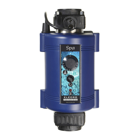
Elecro Engineering Titanium Parts list manual

CE Declaration Of Conformity
Elecro declares that the herewith products or ranges
ELECTRIC AQUATIC HEATER RANGE
Are in conformity with the provisions:
of the ELECTROMAGNETIC COMPATIBILITY directive 89/336/EEC, as amended
93/068/EEC. Controlled by AEMC Measures laboratory—technical report no P96045T
The harmonised standards have been applied: EN 55014—EN 55104
EN 55011
EN 55022
CEI 801-4
CEI 801-2
CEI 801-3
of the LOW VOLTAGE directive 73/23/EEC.
The harmonised standards have been applied
EN 60335-2-35
ELECRO ENGINEERING LTD
Unit 14
Leyden Road
Stevenage
Hertfordshire
SG1 2BW
UK
Tel: +44 (0)1438 749 474
Fax: +44 (0)1438 361 329
Website: www.elecro.co.uk
© Copyright 2004 Elecro Engineering Limited
GUARANTEE
Your Elecro heater is guaranteed for one year from the date of purchase against faulty
workmanship and materials.
ELECRO ENGINEERING LTD will replace or repair, at it’s discretion, any faulty units or
components returned to the company for inspection. Proof of purchase may be required.
ELECRO ENGINEERING LTD will not be liable in cases of incorrect installation of the
heater, or inappropriate use, or neglect of the heater.
PLEASE READ CAREFULLY BEFORE INSTALLING
Do Not Discard, Keep For Future Reference
Incorrect Installation Will Effect Your Warranty
TiTANIUM
Aquatic Heater
& Operating Manual
Installation Instructions

Your Elecro heater must be screw fixed to a firm base or wall. The heater MUST be
horizontal and upright i.e. with the control enclosure located above the Titanium
flow tube (see diagram below). Under no circumstances should the heater be oper-
ated in any other orientation.
NB Diagrams do not show
the digital thermostat
POSITIONING
The heater can be installed on both pump and gravity fed systems. It should
be installed at a low point in the filtration system. To limit weed and debris
build up inside the heater it must be sited after, i.e. downstream, of the filter.
NOTE If the
flow direction
is reversed
(explained
later in this
booklet) the
heater MUST
remain sited
after the filter.
Only clean filtered water
should enter the heater.
NOTES
[Blank Page For Your Notes]

If it becomes necessary to confirm that your Elecro heater is delivering the specified
heat output, an electricity meter reading will be required (taken from the property’s
main electricity meter). Two readings will need to be taken with an exact one hour
interval (i.e. take one meter reading then a second reading exactly one hour later).
Then by subtracting the first reading from the second reading the number of units
(kilo watts / kW) consumed can be calculated. Note that your Elecro heater is also
rated in kW hours. To avoid inaccurate results when performing this test, it is im-
portant to refrain from using other high current drawing appliances in the property
(such as tumble dryer, showers etc). The pond pump and heater will need to be run-
ning (i.e. red light on) continuously during the test. A large pond pump of 1 horse-
power will draw less than 1-kW in a one hour period.
The conclusion of the test should prove that for example a 6-kW heater and a ½
horsepower pump will draw between 6.3-kW to 6.5-kW in one hour. It is impossible
for an Elecro heater to waste energy. All the power drawn by the heater will be
turned into heat and transferred to the water.
Due to the high efficiency of the Elecro heater no warmth should be detectable from
the stainless steel flow tube of the heater.
Possible Cause 3.) Insufficient Flow
The flow rate through the heater needs to be confirmed to be sufficient. Switch off
the circulating pump, close the ball valve unions and un-screw the flow switch. (Use
caution as you will experience a small amount of water loss as you un-screw the
flow switch and conduct the test). With the heater switched on, manually move the
paddle of the flow switch to simulate water flow. If the heater switches on release
the paddle immediately to ensure the unit doesn’t overheat. Reinstall the flow
switch and increase the flow rate through the heater. Chocked filters or blockages
can cause a significant reduction in flow.
No lights appear on the heater when it is switched on
Possible cause: Power Failure external to the heater - Remedy:
Check any fuses, RCD or other switch components installed in the supply cable.
NOTE: the heater is not fitted with a fuse.
TROUBLE SHOOTING CONTINUED PIPE WORK
It is essential that the pipe work connecting to and from the heater has a minimum
bore (internal diameter) of 1¼’’ (32-mm).
To assist correct air purging and to ensure the heater remains completely full of wa-
ter during operation, the return pipe which carries the water back to the pond must
incorporate a safety loop or kick up in the pipe, installed as close as possible to the
heater (see diagram below).
Note: When coupling to flexible pipe, a safety loop can simply be created by routing
the pipe up and over an obstacle. Remember to use pipe clips to securely fasten all
hose connections.
WEATHER PROTECTION
The heater should be installed within a dry weatherproof enclosure.
CAUTION
If the heater is not used during winter months it must be drained to prevent frost
damage.
NOTE: To allow ease of periodic internal cleaning - it is recommended that the
heater is installed with ball valve unions on both water input and output sides. This
will allow the water to be shut off on both sides of the heater to allow removal from
the system.

FLOW REQUIREMENTS
Your Elecro heater is factory set to accept input water flow entering on the left and
exiting on the right, this can be reversed by rotating the flow switch 180° (i.e. ½
turn) (see diagram on following page).
The heater must be installed in accordance with the country / regional requirements
& regulations. In any event the work must be carried out by a qualified electrician,
who will provide a certificate of conformity upon completion of the work. The
power supply must be fitted with a RCD.
Cable section: should be calculated at 5-amp / mm² for distances up to 20 metres
(these sections are indicative and should be checked and adapted if necessary for
cable lengths over 20 metres).
ELECTRICAL CONNECTION
Power Output VOLT (V) AMP
1-kW 230 5
2-kW 230 9
3-kW 230 13
4-kW 230 18
6-kW 230 27
8-kW 230 35
3 Phase
6-kW 400 9
8-kW 400 13
POWER REQUIREMENTS
TROUBLE SHOOTING
5= If Continuously Illuminated
Indicates that the current water temperature
has fallen below the set point temperature.
Heater will not switch from standby to on (red light)
In most cases this will be the result of one of the following not being met.
Possible Cause 1.) The set point temperature has been achieved.
To confirm that the digital thermostat is requesting the unit to heat, see if there is an
illuminated dot above the word ‘out’ on the digital thermostat (5 on diagram below).
If illuminated go to step 2, if not illuminated raise the set point temperature to a
value higher than the current water temperature. Confirm whether the heater now
switches to ‘Heat On’ mode (red light).
Possible Cause 2.) The high limit thermostat has tripped.
Remedy; remove button cover and press red button to re-set (See diagram below).
If a positive click is felt, the cause of the tripping must be investigated and could be
caused by a debris build up or air pocket forming inside the flow tube of the heater.
U
P
TLZ 11
OUT AL
5 = If Flashing
Indicates that the unit is in time delay mode
Step 2 - Push the red button
Step 1 - Unscrew the black cover
NB Diagram does not show digital thermostat

OPERATING YOUR ELECRO HEATER
Upon completion of the installation, run the water-circulating pump to purge the
system & heater of air. (i.e. Remove any trapped air in the system & heater).
On initial power up of the heater the amber light should illuminate. Only when the
water circulating pump is operational and delivering in excess of 1,000-litres per
hour of flow (220 UK gallons) and the digital thermostat is set to a value higher
than that of the water temperature, will the red indicator light turn on and the amber
indicator light turn off. In this mode the heater is on and heating.
*Set Point (Note) The set point is the maximum temperature that the digital ther-
mostat will allow the water to be heated to. Upon reaching the set point temperature
the digital thermostat will switch the heater off, it does not increase or decrease the
power output of the heater.
Warning!
When deciding upon the set point temperature, remember that Koi can be trauma-
tised if their environmental temperature is dramatically changed over a short period
of time, any changes should be made gradually.
TIME SWITCHING DELAY
To prevent overheating of the switch components within the heater caused by fre-
quent on and off switching (cycling), the digital thermostat has been pre-
programmed with a time delay function. This prevents rapid fluctuations in water
temperature from switching the heater on and off more than once in a two minute
period.
The time delay mode is indicated by the flashing of red indicator 6 on the digital
thermostat (see diagram on following page).
Differential:
When the water has reached the set point temperature the heater will switch off and
will not switch back on until the water temperature has dropped by 0.6˚C. This
value is known as the differential and is also in place to prevent overheating to the
switch components caused by cycling.
Once the desired set point value has been selected, do not touch any of the keys for
5 seconds. The unit will then revert to displaying the current water temperature, but
will now control the water temperature to a maximum of the selected set point*.
The flow rate of water entering the heater must not exceed 10,000-litres (2,200 UK
gallons) per hour. A higher flow rate will require the installation of a by-pass to pre-
vent damage to the element(s).
The heater will not operate with a flow rate of less than 1,000-litres (220 UK gal-
lons) per hour.
WATER QUALITY
Elecro TiTANIUM Aquatic heaters are suitable for use with salt water and are also
unaffected by PH levels.
Warning!
The flow switch paddle can be damaged when reversing the flow direction if it is
lifted by more than 5-mm from its housing and turned with force. If the flow switch
has been rotated it is important to ensure that it is finally locked in the correct ori-
entation perpendicular (at right angles) to the flow of water.

24 HOUR TIMER (If Fitted)
Setting Up - The Outer dial will need to be set to the current time (when the heater
has been installed and has a constant power supply). Rotate the minute hand slowly
in a clockwise direction, until the correct hour is located at the tip of the arrow
printed on the dial. See Figure 1 below.
Please note that the outer dial is printed with the 24 hour clock i.e. 8:00 am = 8 on
the dial. 8:00 pm = 20 on the dial.
Programming Guide - Tactic Synchronous & Quartz
Programming Switching Times - Once the outer dial has been set to the current
time you will need to position the appropriate tappets to your required on and off
times. The factory set position of all tappets is in the off position, to change any tap-
pets to the on position they must be switched away from the clock face.
See Figure 2 below.
Figure 2
Manual Override - Your 24 hour timer is also fitted with a manual override
switch that is built into the face of the dial illustrated in Figure 1 (top of this page).
This switch has 3 positions which are explained in the table on the following page.
Minute Hand (pointing to arrow printed on dial)
Outer
Dial
Override
Switch
Figure 1
Tappet
ON OFF
Important - The manual override positions are a fixed selection - i.e. the output of
the 24 hour timer will remain ON or OFF (as selected), until the switch is returned
DIGITAL THERMOSTAT INSTRUCTIONS
The digital thermostat fitted to your Elecro Aquatic heater, has been pre-
programmed with all the necessary parameters to ensure reliable service & opera-
tion.
All you need to do is set the temperature you would like to maintain in your pond
(This is called the set point*).
To display / modify the set point* temperature, press and release the P button (see
diagram on following page).
The pre-programmed set point temperature will be displayed.
Press (3) to increase or (2) to decrease the set point*.
TEMPERATURE DISPLAY
The digital thermostat displays the temperature in ˚C.
Switch Position Function
I = Top Position Manual Override = ON: In this position the time clock
is by-passed, and will not affect the operation of the
heater.
¥= Middle Position 24 Hour Timer = ON: Timed Operation Only.
0 = Bottom Position Manual Override = OFF: In this position the heater
will not operate regardless of any other settings.
1 2
34
5
U
P
TLZ 11
OUT AL
1 P Button Used to display / modify the set point
temperature
2 Down
Button Used to decrease the set point value
3 Up Button Used to increase the set point value
4 Not Used NOT USED
5 LED - OUT Indicates that the water has fallen below
the set point temperature.
Table of contents
Other Elecro Engineering Heater manuals
Popular Heater manuals by other brands

HeatStar
HeatStar ERSP-60 Operating instructions and owner's manual

Behler-Young
Behler-Young VP2 Installation, operation & maintenance manual

TESY
TESY HL-202H Usage and Storage Instructions

SIP
SIP Fireball 350 manual

Berner
Berner DTU03-DTU03-1026 instruction manual

Nemco
Nemco 6150-24 Operating and maintenance instructions

Thermor
Thermor Riva 3 Installation and operating manual

Zibro
Zibro SRE 246 E operating manual

Harbor
Harbor 67125 Set up and operating instructions

Ferroli
Ferroli Napoli 600 INSTRUCTIONS FOR USE & INSTALATION

Tylo
Tylo SENSE SPORT USA Installation and user guide

Clatronic
Clatronic HL 3378 instruction manual