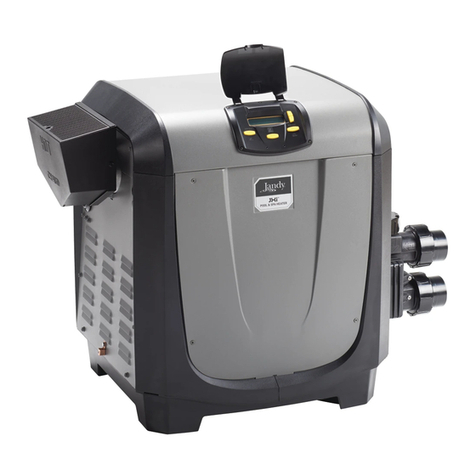
Elecro Engineering 800 Series Parts list manual
Other Elecro Engineering Swimming Pool Heater manuals

Elecro Engineering
Elecro Engineering EVOLUTION Installation instructions
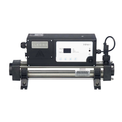
Elecro Engineering
Elecro Engineering In-Line + Swimming Pool Heater Parts list manual
Elecro Engineering
Elecro Engineering FLOW LINE Installation instructions
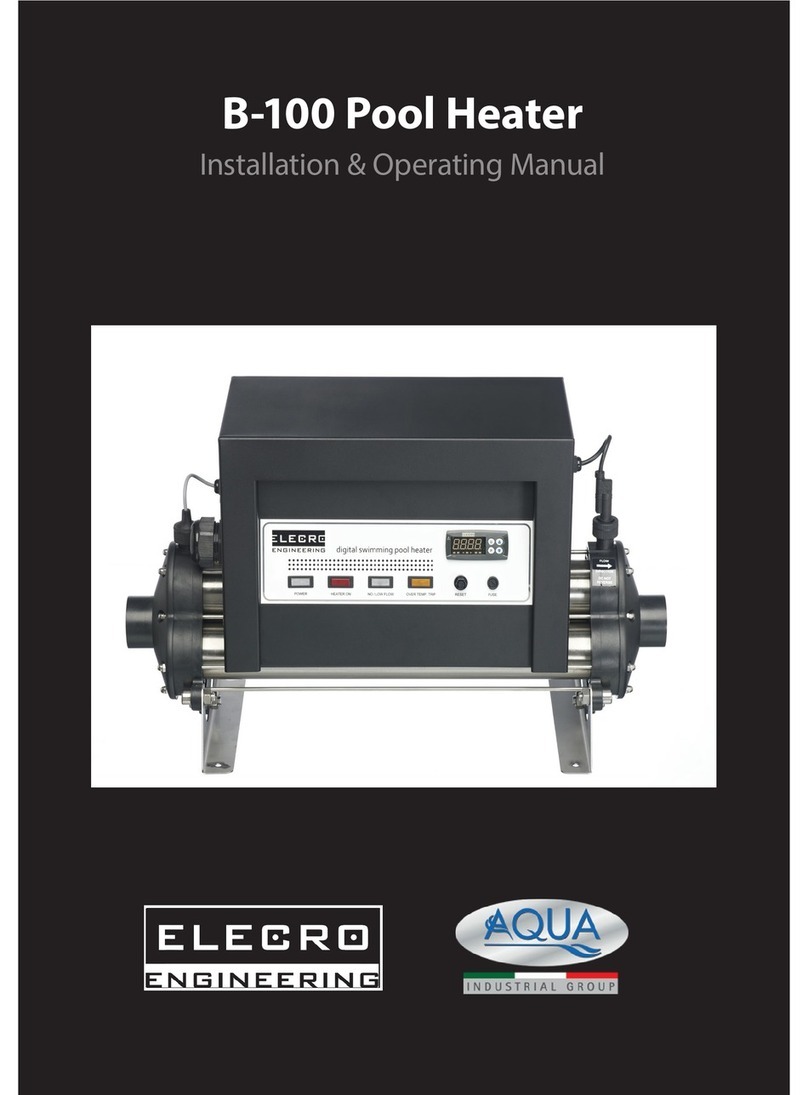
Elecro Engineering
Elecro Engineering B-100 Installation instructions
Elecro Engineering
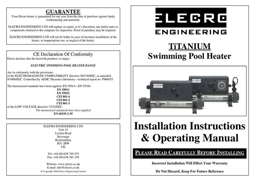
Elecro Engineering TiTANIUM Parts list manual
Elecro Engineering
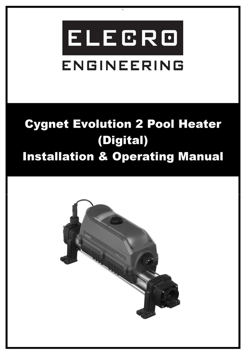
Elecro Engineering Cygnet Evolution 2 Installation instructions
Elecro Engineering
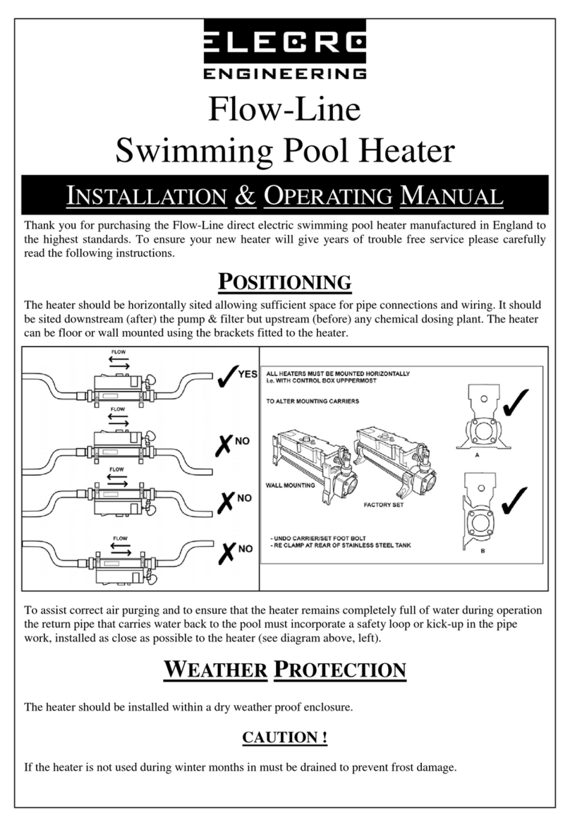
Elecro Engineering FLOW-LINE Installation instructions
Elecro Engineering
Elecro Engineering IN-LINE+ Installation instructions
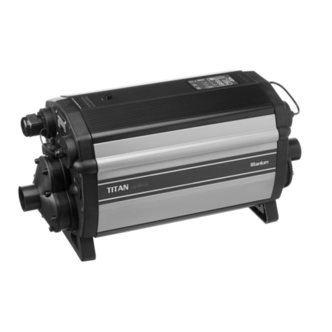
Elecro Engineering
Elecro Engineering Titan Optima Series Installation instructions
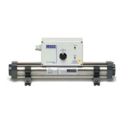
Elecro Engineering
Elecro Engineering 800 Series User manual
Popular Swimming Pool Heater manuals by other brands

Pentair Pool Products
Pentair Pool Products MiniMax CH 150 Operation & installation manual
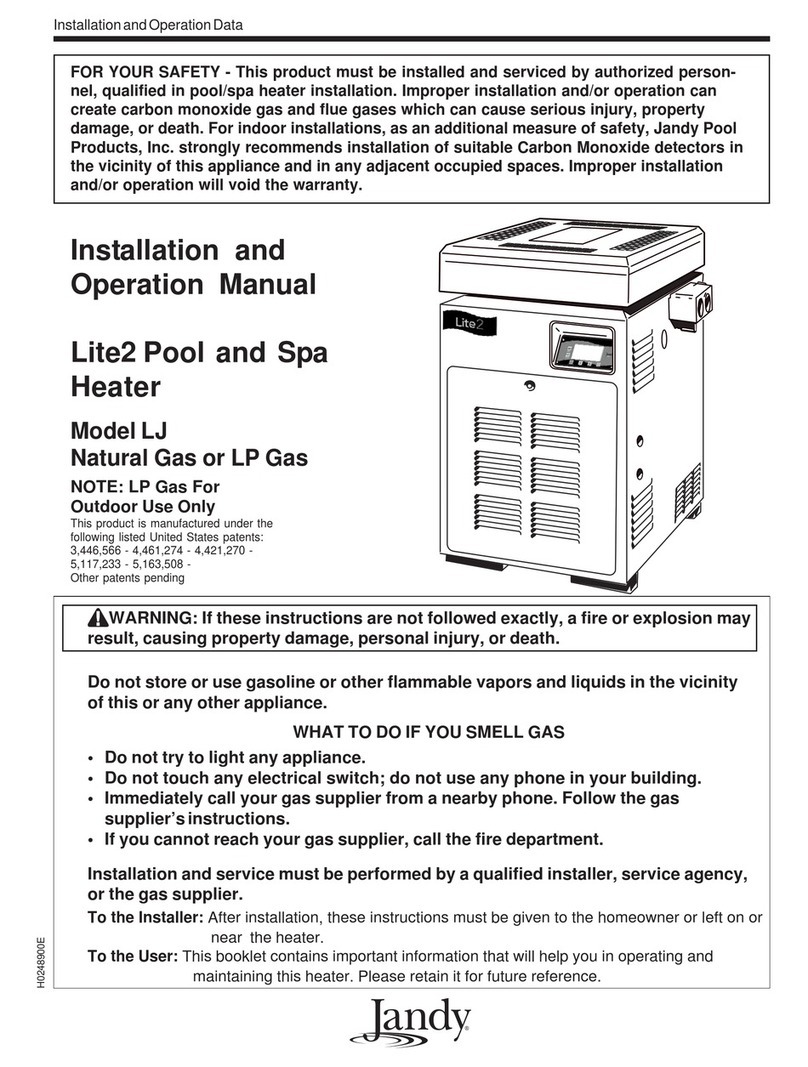
Jandy
Jandy LJ Installation and operation manual

Pentair Pool Products
Pentair Pool Products MiniMax NT Series Operation & installation manual
Raypak
Raypak P-R185A to P-R405A, C-R185A to Installation and operating instructions
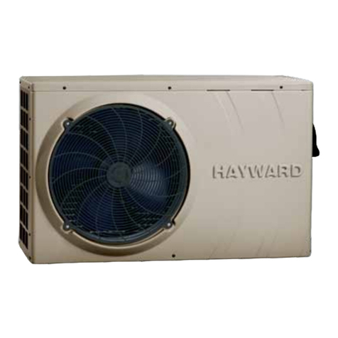
Hayward Pool Products
Hayward Pool Products HP40A Installation instructions manual

Laars
Laars Lite 2 LC Installation and operation manual
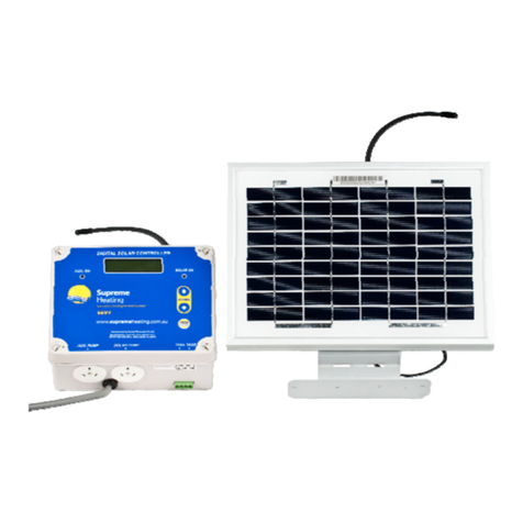
SUPREME
SUPREME Heatseeker Solar Pool Heating user guide
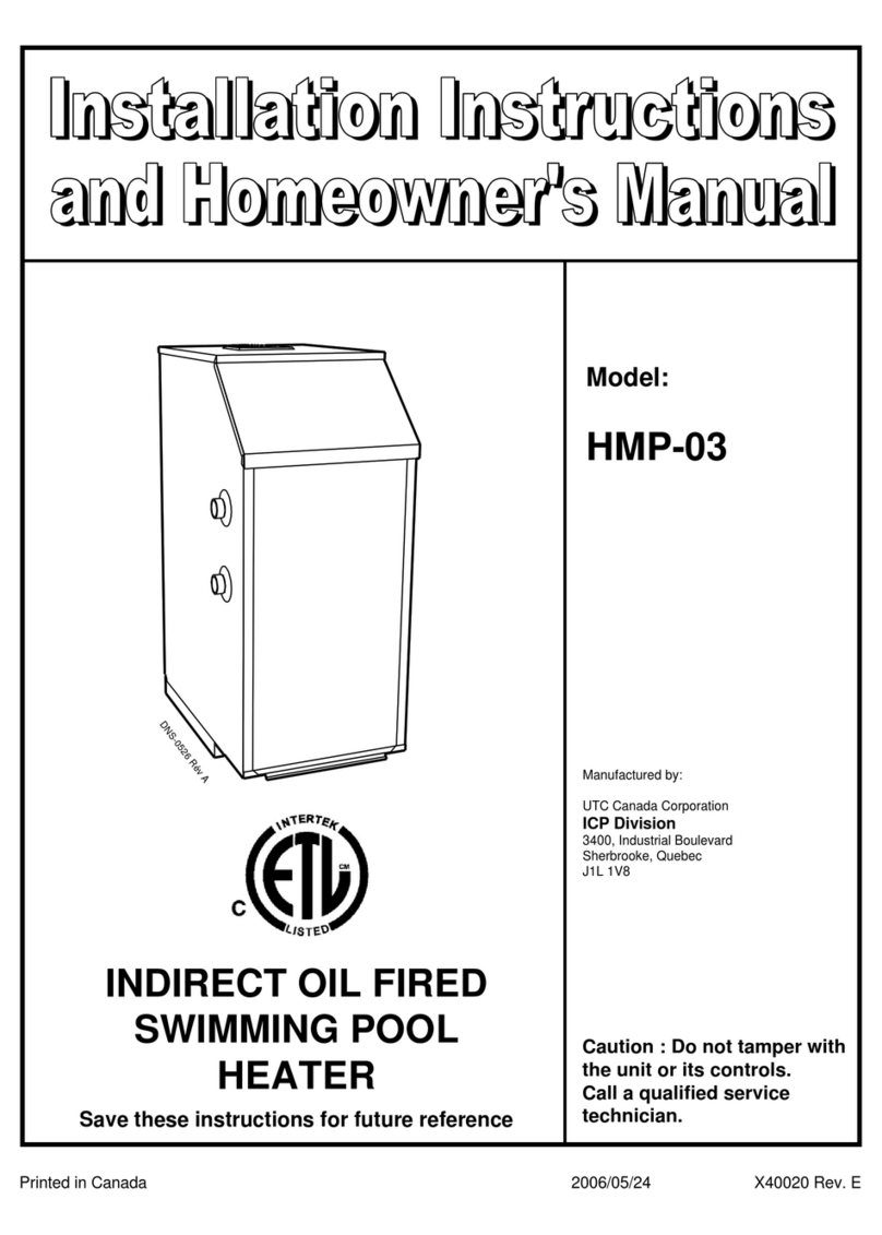
UTC
UTC ICP HMP-03 Installation instructions and homeowner's manual
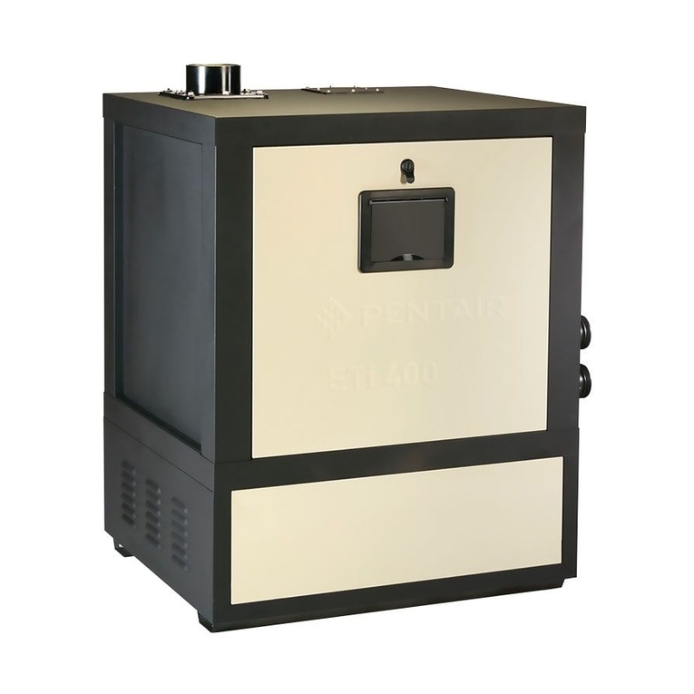
Pentair
Pentair ETi 400 installation guide
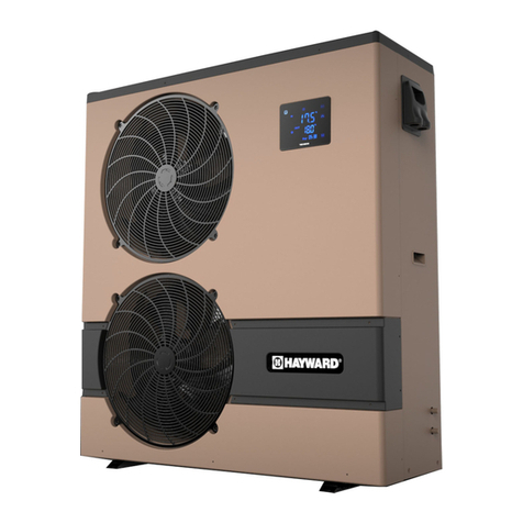
Hayward
Hayward ENP2M-9A Installation instructions manual

BriskHeat
BriskHeat TOT Series instruction manual
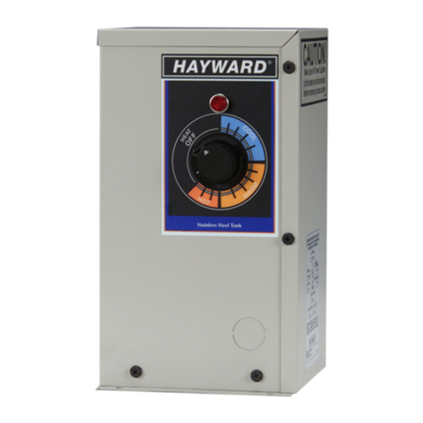
Hayward
Hayward C-SPA-XI 5.5 Installation & operation manual

