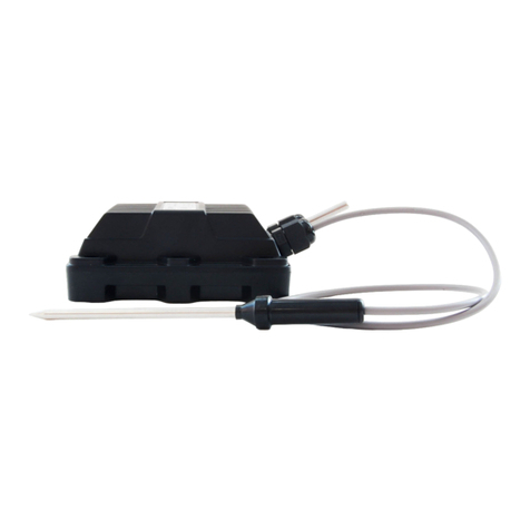
Elecsys WATCHDOG Tracker TR-N1 User manual

Copyright 2017 Elecsys Corporation 81-0046-01 Rev C
Elecsys Watchdog Tracker and Tracker B
Product Manual and Installation Guide
Call Elecsys Customer Support for installation help - (913) 825-6366
Go to www.elecsyscorp.com/Installation for videos and manuals.
Copyright 2017 Elecsys Corporation 81-0046-01 Rev C
WATCHDOG Tracker
CP Test Station Monitor & Data Logger
Critical Bond Monitor
Installation and Product Specication Manual
Test Station/Critical Bond Monitor Systems
Part Numbers:
TR-N1 (CDMA 1xRTT cellular version)
TR-N3 (GSM HSPA+ cellular version)
TR-S3 (Inmarsat IDP satellite version)
WATCHDOG TRACKER

Elecsys Watchdog Tracker and Tracker B
Product Manual and Installation Guide
Call Elecsys Customer Support for installation help - (913) 825-6366
Go to www.elecsyscorp.com/Installation for videos and manuals.
Copyright 2017 Elecsys Corporation 81-0046-01 Rev C
Contents
1Introduction: .................................................................................................................... 3
2Tracker Standard Parts Reference Guide:...................................................................... 4
3Installation:...................................................................................................................... 5
3.1 Website Setup and Conguration:............................................................................ 5
3.2 Installation/Mounting: ............................................................................................... 7
3.3 Connecting the Tracker Wiring:................................................................................ 8
3.4 Measuring AC Current Drain using a CT Coil: ......................................................... 9
3.5 Wiring Diagram:...................................................................................................... 10
3.6 Unit Activation: ...................................................................................................... 11
4Using the Pipeline Watchdog Web Monitor: ................................................................. 12
4.1 Using the Data Logger: .......................................................................................... 12
5Tracker Product Specications: .................................................................................... 13
5.1 Measurement Channel Specications:....................................................................... 14
6Accessories:.................................................................................................................. 14
7Technical Support:........................................................................................................ 14
7.1 Products Under Warranty:...................................................................................... 14
7.2 Products Not Under Warranty: ............................................................................... 15
8Warranty Policy:............................................................................................................ 15
9Sales Contact Information:............................................................................................ 15

Copyright 2017 Elecsys Corporation 81-0046-01 Rev C
Elecsys Watchdog Tracker and Tracker B
Product Manual and Installation Guide
Call Elecsys Customer Support for installation help - (913) 825-6366
Go to www.elecsyscorp.com/Installation for videos and manuals.
Copyright 2017 Elecsys Corporation 81-0046-01 Rev C
Installation Manual and Setup Guide
1 Introduction:
This manual includes instructions and specications pertaining to the following test station and bond
applications for Tracker devices using cellular or satellite communication:
Test Station Monitor Applications:
Simple “structure to reference cell” test points
Single, dual, or triple coupon test stations
Generate alarm notications from out of range readings
AC Monitor Applications:
Measure induced AC voltage on the structure
Measure AC current density at a calibrated coupon
Measure AC drain to ground from an electrical decoupling device (CT coil needed and not supplied
by Elecsys)
Generate alarm notications from out of range readings
Critical Bond Applications:
Measure bond current value and polarity
Measure structure to reference cell for both pipes
Generate alarm notications from out of range readings
The Tracker Monitor is designed to measure, monitor, and report the values typically measured at
CP test stations and critical bond sites. Monitored data is compared to programmable alarm limits
for exception alarm reporting, then transmitted to the Pipeline Watchdog Web Monitor database for
viewing and reporting.
The Pipeline Watchdog Web Monitor allows the user to: 1) set-up e-mail and text message alarms, 2)
set up regular emailed CP rectier and test station data reports, 3) obtain on-demand data reports, 4)
change alarm limit parameters, reporting frequency and monitoring frequency over the air, 5) obtain
any/all stored measurements from the unit memory over the air.
The Tracker is designed for simple installation and operation using the color-coded wire harness and
built-in mounting tabs. The device easily mounts on a riser pipe, post, or utility pole; and the wire
harness accommodates connections to all common test station terminal blocks and bond junction
boxes.
2 Tracker Standard Parts Reference Guide:
Prior to installation, familiarize yourself with the system parts and components included with the unit.
The Tracker includes the monitor unit, 2 mounting brackets, attachment hardware for the mounting
brackets, a connection cable to connect with the measurement points, and 2 ring clamps for mounting
to a 3” PVC riser. If the unit is equipped for satellite operation, it is supplied with the combined
connection/satellite terminal cable, as well as the terminal, terminal bracket, and attachment
hardware.

Elecsys Watchdog Tracker and Tracker B
Product Manual and Installation Guide
Call Elecsys Customer Support for installation help - (913) 825-6366
Go to www.elecsyscorp.com/Installation for videos and manuals.
Copyright 2017 Elecsys Corporation 81-0046-01 Rev C
Tracker
Monitor Unit (self-contained, battery operated, cellular or satellite),
with 7’ (2.1m) 7-conductor measurement connection cable. All
connection wires are insulated.
Satellite Terminal (supplied with satellite units only)
Terminal Mounting Bracket and Fasteners
The following setup guide provides step by step instructions for installation, conguration,
and use of the Watchdog Tracker monitor devices.
3 Installation:
3.1 WebsiteSetupandConguration:
Verify “Site” and “Unit” on the Pipeline Watchdog website (https://secure.pipelinewatchdog.com)
1. Prior to eld installation log into the Pipeline Watchdog website. A “default” site for the
Tracker unit is created at the factory prior to shipment. Locate the default site by doing a
“Search” in the “My Network” section of the website. Select “Unit Serial Number” in the “Search
By” drop-down box, and input the serial number of the unit (located on the label on the back of
the unit), and click the “Search” button on the screen to go to the unit.
2. If unable to locate the Site and Unit using the search tool on the website, contact our
and they will assist you in setting up the unit on the website. Technical support can also
assist with logon problems, password reset, and any other website issues.
3. Prior to doing the eld installation, select the proper unit conguration to be sent to
the unit upon activation in the eld. There are 2 standard congurations for the Tracker,
“Test Station” mode, and “Critical Bond” mode. Each mode has several options.
Unit Conguration
To congure the device, go to the “Site Page” for the unit on the Pipeline Watchdog web monitor (log
in to Pipeline Watchdog → nd site on the Group Page → Click on the site), and click on “Congure
Unit” on the right side of the page. From the congure unit page, click on the “Congure Tracker”
tool button and the conguration screen will appear. Select the conguration type matching your eld
application (Figure 1):

Copyright 2017 Elecsys Corporation 81-0046-01 Rev C
Elecsys Watchdog Tracker and Tracker B
Product Manual and Installation Guide
Call Elecsys Customer Support for installation help - (913) 825-6366
Go to www.elecsyscorp.com/Installation for videos and manuals.
Copyright 2017 Elecsys Corporation 81-0046-01 Rev C
Figure 1. Tracker “Field Application” selection screen
Selecting the mode for your application automatically enables the appropriate channels in the device
and on the web. For example, selecting “Dual Coupon CP Test Station” mode automatically activates
the following channels on the website:
DC pipe to soil potential
AC pipe to soil potential
DC “Instant Off” potential (“disconnected” read from protected coupon)
Induced AC current density (A/m²)
DC protection current level
Native (unprotected) coupon to soil potential
Selecting “Critical Bond (with 2 structure potentials)” activates the following channels:
Bond current (bi-polar indicating direction of current ow)
Primary DC pipe to soil potential
Bonded DC pipe to soil potential
There are 6 default modes from which to choose, plus a “Custom” mode allowing the user to
congure their channel selection to a specic unique application. “Step 3” on page 8 (connecting the
unit in the eld), covers in detail the inputs used and channels activated for each mode.

Elecsys Watchdog Tracker and Tracker B
Product Manual and Installation Guide
Call Elecsys Customer Support for installation help - (913) 825-6366
Go to www.elecsyscorp.com/Installation for videos and manuals.
Copyright 2017 Elecsys Corporation 81-0046-01 Rev C
Following mode selection, you will set the alarm ranges for the enabled channels and enable or
disable alarm notication on the channels (Figure 2):
Figure 2. Channel enable, and alarm parameter selection screen
The eld application selected in the previous section will automatically enable the appropriate
channels for your selected application. You can enable or disable channels if necessary by clicking
in the “Enable” box for that channel. The default “High Alarm” and “Low Alarm” settings may be
changed for your application. Be certain to note the polarity when adjusting these values. The
“Parameter” and “Units” columns indicate the labels applied to the parameter and values on the web
display and in reports. These labels can be edited in the “Data Labels and Descriptions” page in the
conguration section. The “Enable Alarms” check boxes allow you to select what channels will notify
in the event of an out of range reading and what channels will ignore out of range readings.
The bottom section of the unit conguration tool allows you to set the data sampling interval, the
scheduled reporting frequency, and the alarm reminder frequency for the device (Figure 3). The
data sampling time sets the interval at which the device takes readings and stores them to memory.
This can be set for every: 15 seconds, 1 minute, 10 minutes, 1 hour, or 4 hours. The default setting is
every 4 hours. The reporting schedule sets the interval at which the device will send readings to the
website. This interval can be set as frequent as hourly to every 30 days. The default setting is every
14 days. The alarm reminder sets the interval at which the device will re-send an alarm notication
if the alarm has not been addressed and the status is unchanged. The default setting is every 5
days. When all parameters are set, clicking the “Send Conguration” button at the bottom of the
screen sends the conguration parameters to the unit. The device will download the conguration the
next time it contacts the website and send an acknowledgement to the website indicating successful
conguration.

Copyright 2017 Elecsys Corporation 81-0046-01 Rev C
Elecsys Watchdog Tracker and Tracker B
Product Manual and Installation Guide
Call Elecsys Customer Support for installation help - (913) 825-6366
Go to www.elecsyscorp.com/Installation for videos and manuals.
Copyright 2017 Elecsys Corporation 81-0046-01 Rev C
Figure 3. Sampling and reporting interval selection screen
Note: When a new conguration is sent to the Tracker, the internal data card is erased. You
must retrieve any logged data you wish to keep before sending a new conguration.
3.2 Installation/Mounting:
Mounting the Device:
Recommended Installation Tools and Supplies:
Battery powered drill / screwdriver
Wire cutters
Wire stripper
Utility knife
Crimping tool
Multi-meter
Terminals, Spade 18-22AWG - #10 (for connecting wire harness to measurement points)
¼” x2 ½” Lag Screws (if mounting to a 4x4 post, or for satellite terminal mounting)
The Tracker enclosure has an upper and a lower mounting tab for securing the unit to a standard
3” riser pipe. The electronics and the battery pack inside the enclosure are weatherproff, enabling
the unit to be mounted to a post, to the side of a junction box, etc. without exposing the electronics
to the environment.. The connection cable supplied with the unit is 7’ (2.4 meters) in length. Select
a mounting location that allows for this cable length to be sufcient for connecting to the desired
measurement points.

Elecsys Watchdog Tracker and Tracker B
Product Manual and Installation Guide
Call Elecsys Customer Support for installation help - (913) 825-6366
Go to www.elecsyscorp.com/Installation for videos and manuals.
Copyright 2017 Elecsys Corporation 81-0046-01 Rev C
If the Tracker uses satellite communication, the satellite terminal, mounting bracket, and the
necessary hardware to mount the terminal on the bracket are also included. The satellite terminal
must be mounted with a clear view of the sky at the direction and angle of elevation for your location
as shown in the chart below:
Geographic Area Compass Direction Elevation Angle
(angle up from horizon)
Northeastern US 175-185° (S) 35-40°
Southeastern US 175-185° (S) 35-40°
Midwest, Central US 175-185° (S) 25-30°
Southwest US, Texas 175-185° (S) 35-40°
Northwest US 175-185° (S) 30-35°
Columbia, South Am. 355-5°(N) 65-70°
Saudi Arabia, UAE 145-155° (SE) 50-60°
South Africa 355-5°(N) 30-35°
Peru 355-5°(N) 60-65°
Chile, Argentina 355-5°(N) 45-55°
Brazil, Argentina 355-5°(N) 55-75°
Europe 140-160° (SE) 15-30°
India 205-220° (SW) 55-65°
Australia 45-65° (E) 20-30°
When the Tracker and the satellite terminal are both properly mounted, connect the terminal to the
Tracker by inserting the connector on the end of the cable to the input connector at the base of
the satellite terminal. Turn the collar on the connector ¼ turn to secure the connection. Attaching
the wire harness to the measurement points and connecting to the Tracker are covered in the next
sections.
3.3 ConnectingtheTrackerWiring:
Connecting the unit in the eld
The Tracker accommodates input connections for several typical test station or critical bond
monitoring applications. Below are the standard connection points for each color-coded wire lead
in the multi-conductor cable from the monitor unit. Ensure installation is done according to the
instructions in this manual and the product is used for the proper application for proper operation.
Securely fasten all wire connections using the appropriate cord anchorage. Wiring schematic for the
device is on the following page for reference (Figure 6).
Wire Color Connects to:
Brown Pipe Structure
Yellow Reference Cell
Green Protected Coupon*
Blue/Wht Structure 2 or “Native” Coupon
Purple AC Coupon**
Wht/Red CT Coil or Bond Shunt+

Copyright 2017 Elecsys Corporation 81-0046-01 Rev C
Elecsys Watchdog Tracker and Tracker B
Product Manual and Installation Guide
Call Elecsys Customer Support for installation help - (913) 825-6366
Go to www.elecsyscorp.com/Installation for videos and manuals.
Copyright 2017 Elecsys Corporation 81-0046-01 Rev C
Wht/Yellow CT Coil or Bond Shunt–
*If “On Potential” and “Off Potential” is to be measured, the “Protection On/Off” switch in the test
station must be set to the “Off” position.
** If connecting to a single or dual coupon test station, connect the AC coupon lead to the “Protected”
coupon terminal.
Illustrated wiring diagram is on the following page.
Note: Not all wires are used in all applications. “Tape off” any unused wires to insulate from
interference or shorting.
These connection options cover most applications for which the Tracker is designed. If your
application includes conguration or connections not covered in these typical setups, please contact
our Technical Support Department at (913) 825-6366 and we will be happy to assist you in setup for
custom applications.
3.4 MeasuringACCurrentDrainusingaCTCoil:
A “CT coil” current sensor (not supplied) is necessary to measure AC drain to ground.
Refer to the “CT Coil Selection Guide” below for recommendations for selecting amp
range, etc.
4.5 Scout Wiring Diagram

Elecsys Watchdog Tracker and Tracker B
Product Manual and Installation Guide
Call Elecsys Customer Support for installation help - (913) 825-6366
Go to www.elecsyscorp.com/Installation for videos and manuals.
Copyright 2017 Elecsys Corporation 81-0046-01 Rev C
3.5 WiringDiagram:
Figure 6. Tracker wiring diagram

Copyright 2017 Elecsys Corporation 81-0046-01 Rev C
Elecsys Watchdog Tracker and Tracker B
Product Manual and Installation Guide
Call Elecsys Customer Support for installation help - (913) 825-6366
Go to www.elecsyscorp.com/Installation for videos and manuals.
Copyright 2017 Elecsys Corporation 81-0046-01 Rev C
3.6 Unit Activation:
Activation:
When the unit is installed and connected to the measurement points, it is ready for activation. The
Tracker device is battery powered. It comes from the factory ready for activation. To power on the
unit and initiate the rst communication to the website, press and hold the pushbutton on the side of
the unit for 4 seconds until the LED begins ashing. The unit will initialize, establish communication
with the cellular system or the satellite system, then retrieve a conguration from the website. When
the startup sequence is completed the device will commence taking measurements and reporting to
the website as scheduled.
To activate the Tracker and download the conguration selected in Step 1, push the button on
the base of the unit and a “Request for Conguration” command will be sent to the website. The
conguration will download to the device and an acknowledgement will be transmitted from the unit to
the website.
The LED on the front of the unit provides status information during setup and pushbutton
communication cycles. The table below indicates the status conveyed through the LED patterns:
State Communication Status LED Behavior
Uncongured Idle LED on solid
Congured Idle
Signal strength (1 to
4 quick blinks every 3
seconds)
Transmitting/Receiving
“Conguration Request”
packet sent, awaiting
acknowledgement
ON one second, OFF
one second
Transmitting/Receiving
“ACK” (Acknowledgement
received or Conguration
received. Unit operating
normally)
Signal strength (# of
ashes = “bars”)
Transmitting/Receiving Communications timeout
Rapid, continuous
blinks
Transmitting/Receiving
“NACK” (Communication
established, but no
acknowledgement
received, website setup
problem) LED on solid
Transmitting/Receiving Insufcient signal strength
Rapid, continuous
blinks
When the “status” LED is ashing the communication signal strength (1 to 4 rapid ashes every
3 seconds) communication with the Pipeline Watchdog website is successful. The LED will
automatically turn off following a successful transmission. This completes the eld installation.

Elecsys Watchdog Tracker and Tracker B
Product Manual and Installation Guide
Call Elecsys Customer Support for installation help - (913) 825-6366
Go to www.elecsyscorp.com/Installation for videos and manuals.
Copyright 2017 Elecsys Corporation 81-0046-01 Rev C
4 Using the Pipeline Watchdog Web Monitor:
Once the Tracker is properly installed in the eld, the user’s primary contact with the system will
come by using the website. All programming for alarm thresholds, reporting frequency, interrupter
parameters, etc. is done over the web.
To change any of the parameters in the conguration at any time, go to the “Congure Unit” selection
page for that site on the Pipeline Watchdog web interface and select the changes desired then click
on “Send Conguration” to send the changes. The Tracker will download the new conguration the
next time it communicates to the website and a “CONFIG ACK” (conguration acknowledgement)
response will be received from the unit to the website indicating the conguration change was
successful.
4.1 UsingtheDataLogger:
The Tracker will automatically log all readings for enabled channels to a 2GB SD memory card in the
device. The logged data can then be retrieved by downloading the data to the website. To retrieve
logged data over the web click on the “Data Logger” button on the site page of the unit. The following
“Data Logger File Retrieval” screen will open (Figure 7):

Copyright 2017 Elecsys Corporation 81-0046-01 Rev C
Elecsys Watchdog Tracker and Tracker B
Product Manual and Installation Guide
Call Elecsys Customer Support for installation help - (913) 825-6366
Go to www.elecsyscorp.com/Installation for videos and manuals.
Copyright 2017 Elecsys Corporation 81-0046-01 Rev C
Figure 7. Data Logger le retrieval screen
The le retrieval screen allows you to select a date range, sample frequency, and the channel(s) from
which you want to retrieve data. The sample frequency resolution will not be greater than the sample
frequency set in the conguration (i.e. if the unit is sampling once every hour, only those samples are
being logged to the card). When the date range, sample frequency, and channels are selected for
the download, click on the “Calculate File Size and Cost” button to calculate the cost of the download.
IMPORTANT NOTE! There is an additional communication charge of $0.10/kilobyte of
data downloaded (1kb of data is equivalent to approximately 2 weeks of sampling all
measurements at 1 hour intervals).

Elecsys Watchdog Tracker and Tracker B
Product Manual and Installation Guide
Call Elecsys Customer Support for installation help - (913) 825-6366
Go to www.elecsyscorp.com/Installation for videos and manuals.
Copyright 2017 Elecsys Corporation 81-0046-01 Rev C
When the le size and download cost has been calculated, click on “Send File Request” to send the
command to the Tracker. The data will be downloaded the next time the unit communicates with the
website. The “Data Logger Requests” log at the bottom of the page (Figure 8). The requests log
indicates the status of the request (pending or complete). When the request is completed, the le
is accessed by clicking on the “Download” link under “Actions” on the right of the screen. The le is
opened in an Excel page as a comma separated value (.csv) spreadsheet. The downloaded le can
be copied, saved, and exported from the Excel view.
5 Tracker Product Specications:
Part Number CDMA cellular telemetry: TR-N1
GSM cellular telemetry: TR-N3
IDP satellite telemetry: TR-S3
Input Connections
All connection wires are
insulated. Be certain
all wire connections
are properly secured
and fastened with
the appropriate cord
anchorage.
Structure 1 (pipeline)
Structure 2 (second pipeline or “native” coupon)
Reference cell
“Protected” coupon
“AC” coupon
(Note: if no dedicated AC coupon is used AC measurements can be
taken on the “protected” coupon)
Shunt/CT coil +
Shunt/CT coil –
Data-logging Embedded SD - >15 years of samples at 15 second sample rates.
(faster rates available with custom congurations)
Sample frequency up to every 15 seconds
Power Li-SOCL2 Lithium battery (3 to 5 year life under normal conditions
and operating parameters)
(NOTE: the Elecsys P/N: 49-0046-00 battery pack is the only
authorized battery replacement!)
Connection for external power: 6.5 to 18 VDC
(nominally 12V solar).
Solar panels or solar power system not supplied by Elecsys
Corporation
Operating Environment Temperature: -40°C to +70°
Humidity: 0-95% non-condensing
Enclosure IP66 rated, 14” (35.5cm) x 3 3/8” (8.6cm) x 3” (7.62cm)

Copyright 2017 Elecsys Corporation 81-0046-01 Rev C
Elecsys Watchdog Tracker and Tracker B
Product Manual and Installation Guide
Call Elecsys Customer Support for installation help - (913) 825-6366
Go to www.elecsyscorp.com/Installation for videos and manuals.
Copyright 2017 Elecsys Corporation 81-0046-01 Rev C
5.1MeasurementChannelSpecications:
Measurement Channel Channel Range Accuracy
DC potential (structure 1 to reference) -10V to +10V 1mV
AC potential (structure 1 to reference) 0 – 35V rms 10mV
DC Potential (structure 2 or native to reference) -10V to +10V 1mV
AC potential (structure 2 or native to reference) 0 – 35V rms 10mV
Protected coupon “instant off” (coupon to ref.) -10V to +10V 1mV
AC current density (structure 1 to coupon drain)* 0 – 500 mA rms 0.1mA
DC protection current density (structure 1 to coupon) -100mA to +100mA 0.1mA
AC drain current (voltage across external CT coil) 0 – 500 mV rms 0.1mV
DC bond shunt current (across external shunt) -150mV to +150mV 0.1mV
* Note: the Tracker can simultaneously/alternatively calculate AC current density using the
pipeline AC voltage potential measurement and a user supplied soil resistivity measurement
value constant.
6 Accessories:
Description Part Number
External cellular High-Gain Antenna Kit 48-0003-21
(includes: antenna, bracket, and adapter)
Replacement Battery Pack 49-0046-00
(NOTE: this battery pack is the only authorized battery replacement!)
7 Technical Support:
In the event of a problem, Elecsys always stands ready to provide prompt service and technical
support.
Elecsys Technical Support Hours: 8AM to 5PM Central time, Monday through Friday
Elecsys Technical Support Direct Phone: 913-825-6366.
Most support issues are quickly resolved over the phone. If the problem cannot be resolved by
phone, Elecsys will arrange for repair or replacement equipment as soon as possible to get the site
operational once again.
During the Warranty Period, Elecsys will repair or replace problems systems or components at its
expense. After the Warranty Period expires, Elecsys will repair or replace failed components for a fair
and reasonable charge.

Elecsys Watchdog Tracker and Tracker B
Product Manual and Installation Guide
Call Elecsys Customer Support for installation help - (913) 825-6366
Go to www.elecsyscorp.com/Installation for videos and manuals.
Copyright 2017 Elecsys Corporation 81-0046-01 Rev C
7.1 Products Under Warranty:
Call Elecsys Technical Support at 913-825-6366.
Upon determination by Elecsys that the problem is related to a cause that is covered under this
warranty, instructions for returning the Product will be provided, as well as an RMA number.
A repaired or replacement Product is warranted in accordance with the terms of the standard limited
warranty, for the balance of the term applicable to the inoperative Product.
Upon its examination, if the inoperative Product is found to have problems not covered under the
warranty, Elecsys reserves the right to charge for repair services.
Replacement parts or Products will be shipped to domestic customers at Elecsys’ expense, subject to
availability, via ground delivery service and at international customers’ expense. Elecsys shall not be
responsible for failure of the delivery service to make on-time delivery.
7.2 Products Not Under Warranty:
Call Elecsys Technical Support at 913-825-6366.
Upon determination by Elecsys that the problem is related to a cause that must be remedied by Elecsys,
instructions for returning the Product will be provided, as well as an RMA number.
A purchase order or other such authorization will be required to cover the cost of repair or a replacement
Product.
A repaired or replacement Product is warranted in accordance with the terms of the standard limited
warranty, for a period of 90 days following installation and activation.
8 Warranty Policy:
For a period of eighteen (18) months from the date of shipment, Elecsys warrants that its products will
be free from defects in workmanship and materials.
For the same period, Elecsys warrants that its products will perform to their specications and, to the
extent Elecsys is informed of the use(s) for which the original purchase is made, are t for such use(s).
NO OTHER WARRANTY, EXPRESS OR IMPLIED IS MADE OR MAY BE IMPLIED.
Any claim that an Elecsys product is defective shall be made in writing and supported by such detail
and/or documentation as Elecsys shall reasonably require.
9 Sales Contact Information:
Please contact Elecsys Remote Monitor Sales at (913) 888-5222 or by email: [email protected]
for order and pricing information.

Copyright 2017 Elecsys Corporation 81-0046-01 Rev C
Elecsys Watchdog Tracker and Tracker B
Product Manual and Installation Guide
Call Elecsys Customer Support for installation help - (913) 825-6366
Go to www.elecsyscorp.com/Installation for videos and manuals.
Copyright 2017 Elecsys Corporation 81-0046-01 Rev C
Our Commitment –
The goal of the Remote Monitor division of Elecsys Corporation is to provide you with the best
products and service available in the industry. If you encounter any difculties, or have any questions
or concerns, before, during or following installation, please contact our Technical Support Team:
(913) 825-6366 or [email protected] . We are fully staffed Monday through Friday, from
7:00am Central Time to 5:00pm Central Time and WE ARE HERE TO HELP!
Elecsys Corporation
846 N. Mart-Way Ct.
Olathe, KS 66061
(913) 888-5222 Main Phone
(913)825-6366 Technical and Field Support Line
This manual suits for next models
2
Table of contents
