StewMac Monarch User manual

stewmac.com ©2018 StewMac page 1 of 14
Sheet #i-2205 Updated 5/18
CLASSIC PEDAL KIT
Monarch
StewMac
Assembly
Instructions
The Monarch Overdrive is an all
discrete, FET-based dirt machine.
It’s designed around the input stage
of a vintage amp but congured to
produce higher gains that sound
very open and free of unnatural
compression. The Monarch gives big
bottom end with a snappy, bright top at all gain ranges with
some careful tuning of the treble and bass controls. The
treble and bass controls function as frequency boosters,
not the traditional roll o lters in most overdrives. They are
located in the preamp section and have a large impact on
the over all tone, nature and distortion characteristics. If you
are looking for an overdrive for big fat chords with excellent
low end retention, this is it!
An EarthQuaker Devices original, the Monarch Overdrive
has been out of production for some time, but now you can
build your own!
IN COLLABORATION WITH
Easy instructions!
Clear pictures show where
each part goes.
RARE / VINTAGE / HARD TO GET
WHEN YOU CAN’T BUY IT BUILD IT
EarthQuakerDevices™
Kit case is unpainted
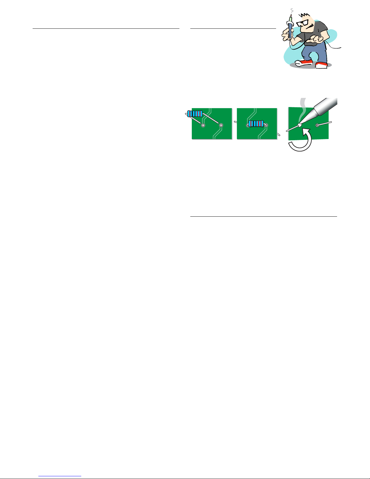
Tips for soldering
The solder joints you’ll make on the
circuit board are very small, and too
much heat can damage the board.
The idea is to make joints quickly,
without scorching the eyelets.
Hold components in place for soldering by threading the
leads through the board and bending them apart on the
reverse side.
Make your solder joints on the reverse side. Insert the tip into
the eyelet and let it heat for 4-5 seconds before touching it
with solder. This heats the contact enough for the solder to
ow nicely without damage. You don’t need much solder,
just enough to ll the eyelet. After soldering, trim away the
excess lead wire.
Give your pedal a custom paint job!
Any paint sold for use on metal will work well on the kit case.
Spray paints like Rustoleum® or Krylon® are a durable nish.
You might want to paint the case before building the kit,
so you won’t need to take the parts back out for painting.
A way to add custom graphics is to print them from your
computer onto waterslide decal paper. If you use decals,
protect them from scratches by spraying clear topcoats
over them.
Tools and supplies
Required: Soldering iron with ne point tip
Solder
Wire cutter/stripper
3/8" nut driver or socket
1/2" nut driver or socket
10mm nut driver or socket
14mm wrench
#1 Phillips screwdriver
Also helpful: Clear silicone adhesive
Circuit card holder
Magnifying glass or OptiVISOR
StewMac Soldering Aids
Power: This pedal requires a standard 9V DC
center-negative power supply or 9V battery
(neither included) and consumes less than
100mA.
stewmac.com ©2018 StewMac page 2 of 14
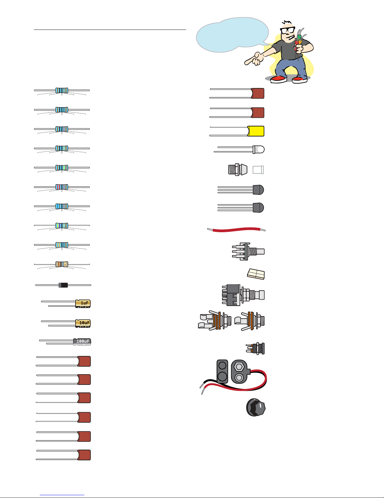
Parts list
Resistor values are indicated by colored bands, read from left
to right. The rst color in the code is usually the one painted
closest to a lead wire. When a gold or silver band is present,
it’s always one of the last colors in the code. A magnier is
a big help in reading these codes.
stewmac.com ©2018 StewMac page 3 of 14
Save time: sort the
components by type
before you art!
.47µF capacitor (1) #7336
474J
100V
474J 100V
5mm LED mounting bezel (1) #7432
470pF capacitor (1) #7328
parts: i-2205 Monarch Overdrive
1KΩ resistor (1) #7357
Brown Black Black Brown Brown
10µF capacitors (2) #7338
100µF capacitor (1) #7339
220pF capacitor (1) #7327
221J
100V
221J 100V
471J
100V
471J 100V
.001µF capacitors (2) #7329
102J
100V
102J 100V
5mm white LED (1) #7422
BS170 transistor (1) #7485
2N5457 transistors (3) #7486
A1MΩ audio taper pots (3) #7459
B100KΩ linear taper pot (1) #7453
24" of lead wire (1) #5960
Adhesive foam tape squares (4) #7560
PT2399
1µF capacitors (2) #7337
Brown Black Black Black Brown
100Ω resistor (1) #7352
1N4001 rectier diode (1) #7404
10uF
1uF
100uF
100pF capacitors (2) #7326
101J
100V
101J 100V
.022µF capacitor (1) #7332
223J
100V
223J 100V
.0022µF capacitor (1) #7330
222J
100V
222J 100V
.01µF capacitors (2) #7331
103J
100V BS
170 2N
5457
103J 100V
.0047µF capacitor (1) #7321
.0047J
100n
.0047J 100n
Stereo Mono
3PDT latching footswitch (1) #1611
Metal case with 4 screws (1) #7601
Circuit board (1)
(Not pictured)
(Not pictured)
1/4" stereo jack (1) #4653
1/4" mono jack (1) #4652
2.1mm DC power connector (1) #7467
9V battery clip (1) #1222
Protective cap (1) #1227
Control knobs (4) #7501
Brown Black Black Yellow Brown
1MΩ resistors (3) #7367
Brown Black Black Red Brown
10KΩ resistors (4) #7362
Brown Black Black Orange Brown
100KΩ resistor (3) #7365
Red Red Black Red Brown
22KΩ resistors (2) #7379
Blue Gray Black Red Brown
68KΩ resistor (1) #7380
Yellow Purple Black Orange Brown
470KΩ resistor (1) #7382
Blue Gold
Brown Black
10M resistors (2) #7383
Orange Orange Black Black Brown
330Ω resistor (1) #7375

stewmac.com ©2018 StewMac page 4 of 14
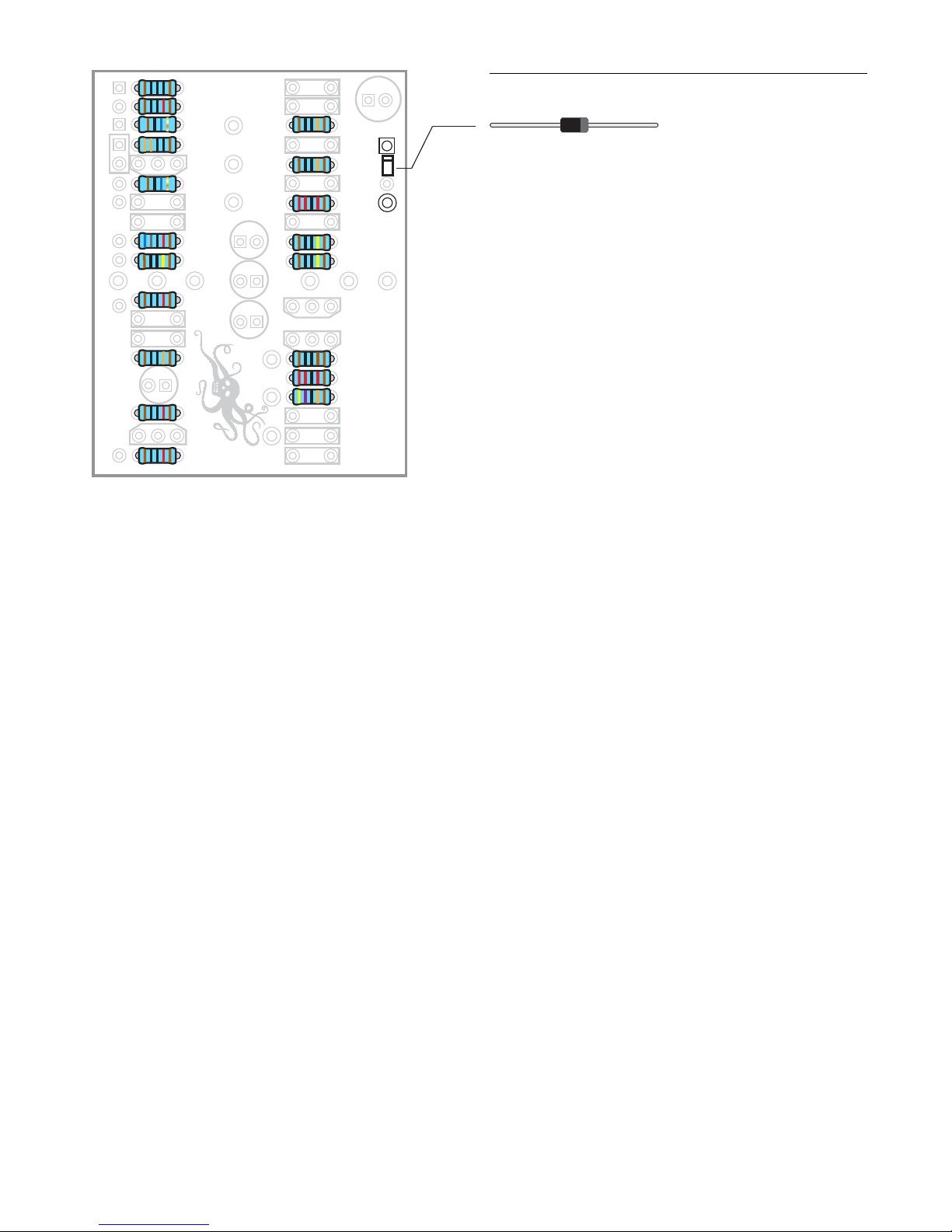
Step 1: Install nineteen resistors
As you get started, note that the values of each component
are printed in their proper location on the circuit board un-
less otherwise noted.
Resistors have a low prole, sitting closer to the board than
taller components, so install them rst. Their locations are
marked on the board with the value of the part.
Resistors are not polarized, so it doesn’t matter which lead
goes in which eyelet. They can be installed in either direction.
Larger resistors may need to be placed on the
board at an angle due to their size.
V–V+ B+ B+ B– B– GO
IGL
.47
.022
.001
.0047
.0022
22K
1M
1M
1 M
10 M
330
220 p
10 M
10 K
10 K
100 p
100
100K
10 K
68K
100p
.01
10K
1K
22 K
470 K
.001
470 p
100u
10
1
1
10
.01
100K
100 K
V–V+ B+ B+ B– B– GO
IGL
.47
.022
.001
.0047
.0022
22K
1M
1M
1 M
10 M
330
220 p
10 M
10 K
10 K
100 p
100
100K
10 K
68K
100p
.01
10K
1K
22 K
470 K
.001
470 p
100u
10
1
1
10
.01
100K
100 K
EarthQuaker Devices
Monarch Rev 2 | 2011
EarthQuaker Devices
Monarch Rev 2 | 2011
Brown Black Black Orange Brown
100KΩ resistors (3) #7365
Red Red Black Red Brown
22KΩ resistors (2) #7379
Blue Gray Black Red Brown
68KΩ resistor (1) #7380
Brown Black Black Yellow Brown
1MΩ resistors (3) #7367
Brown Black Black Red Brown
10KΩ resistors (4) #7362
Yellow Purple Black Orange Brown
470KΩ resistor (1) #7382
Blue Gold
Brown Black
10MΩ resistors (2) #7383
Orange Orange Black Black Brown
330Ω resistor (1) #7375
1KΩ resistor (1) #7357
Brown Black Black Brown Brown
Brown Black Black Black Brown
100Ω resistor (1) #7352
stewmac.com ©2018 StewMac page 5 of 14
Step 2: Install one diode
Diodes are polarized, so they need to be installed in the
correct orientation.
Note the stripe around one end: this marks the negative
(minus) lead of the diode. On the circuit board, the printed
outline of the diodes also shows this stripe. Install each
diode so that its stripe matches the direction shown on the
circuit board.
1N4001 rectier diode (1) #7404
Either round eyelet can be used here
V–V+ B+ B+ B– B– GO
IGL
.47
.022
.001
.0047
.0022
22K
1M
1M
1 M
10 M
330
220 p
10 M
10 K
10 K
100 p
100
100K
10 K
68K
100p
.01
10K
1K
22 K
470 K
.001
470 p
100u
10
1
1
10
.01
100K
100 K
EarthQuaker Devices
Monarch Rev 2 | 2011
stewmac.com ©2018 StewMac page 6 of 14
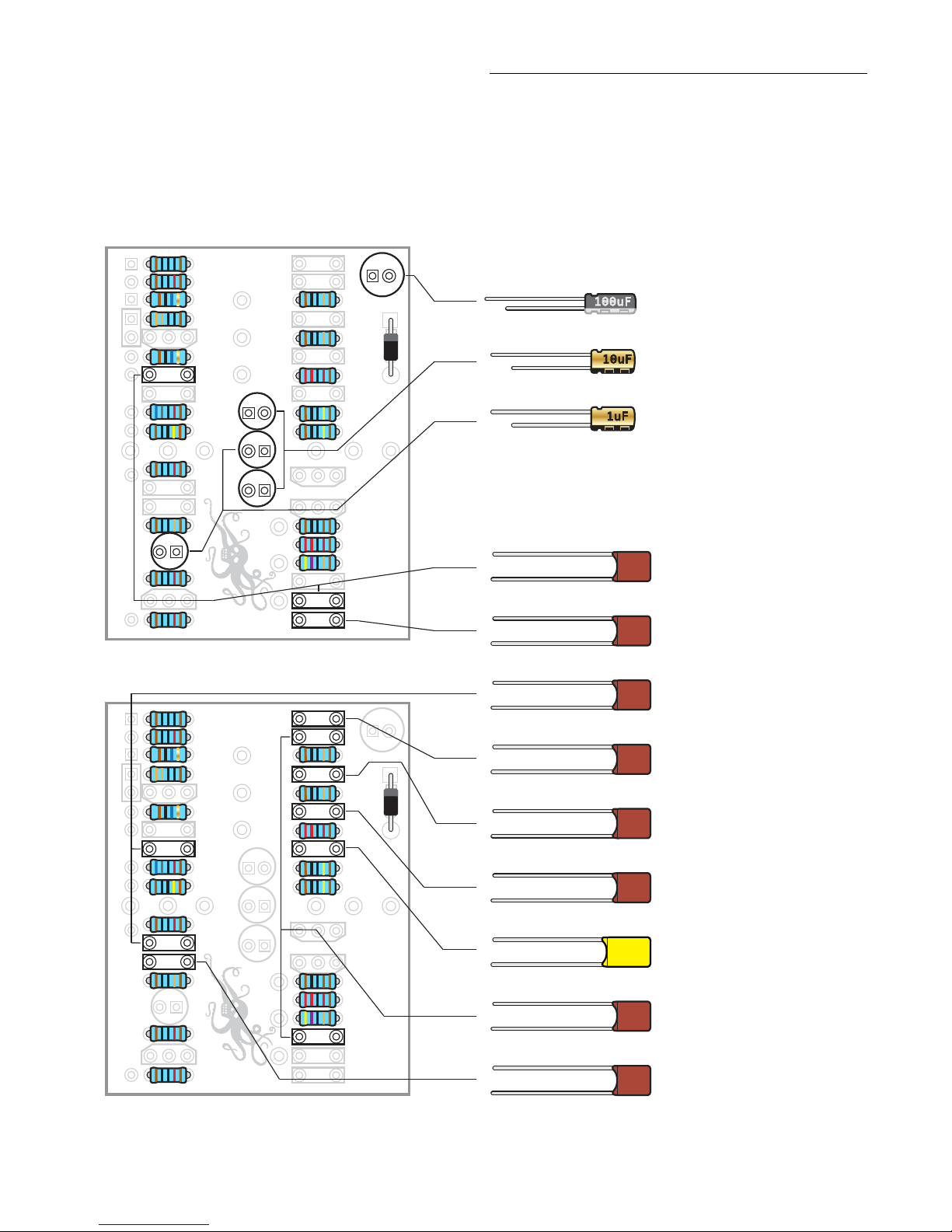
Step 3: Install seventeen capacitors
The three types of capacitors shown below are polarized,
and have to be installed in the correct orientation. Note
the stripe running the length of each cap; this identies the
negative (minus) lead. On the circuit board, the circle for this
cap’s location has a round through hole on one side, and a
square through hole on the other: insert the capacitors with
their stripe facing the round hole side. (On polarized caps of
this type, there’s a second way to identify the minus lead: it
is the shorter of the two leads.)
The remaining capacitors below are not polarized. Solder
these caps in place facing either direction.
V–V+ B+ B+ B– B– GO
IGL
.47
.022
.001
.0047
.0022
22K
1M
1M
1 M
10 M
330
220 p
10 M
10 K
10 K
100 p
100
100K
10 K
68K
100p
.01
10K
1K
22 K
470 K
.001
470 p
100u
10
1
1
10
.01
100K
100 K
V–V+ B+ B+ B– B– GO
IGL
.47
.022
.001
.0047
.0022
22K
1M
1M
1 M
10 M
330
220 p
10 M
10 K
10 K
100 p
100
100K
10 K
68K
100p
.01
10K
1K
22 K
470 K
.001
470 p
100u
10
1
1
10
.01
100K
100 K
EarthQuaker Devices
Monarch Rev 2 | 2011
EarthQuaker Devices
Monarch Rev 2 | 2011
474J
100V
474J 100V
221J
100V
221J 100V
471J
100V
471J 100V
102J
100V
102J 100V
10uF
100uF
101J
100V
101J 100V
223J
100V
223J 100V
222J
100V
222J 100V
103J
100V
103J 100V
.0047J
100n
.0047J 100n
1uF
10µF capacitors (2) #7338
100µF capacitor (1) #7339
1µF capacitors (2) #7337
.47µF capacitor (1) #7336
470pF capacitor (1) #7328
220pF capacitor (1) #7327
.001µF capacitors (2) #7329
100pF capacitors (2) #7326
.022µF capacitor (1) #7332
.0022µF capacitor (1)
#7330
.01µF capacitors (2) #7331
.0047µF capacitor (1)
#7321

stewmac.com ©2018 StewMac page 7 of 14
Step 5: Install nine lead wires
The kit comes with 24" of lead wire. Cut the wire into 2”
sections. This will give you twelve 2" sections.
Strip around 3/32" of both ends of the 2" pieces. On one of
the 2" pieces, strip 1/4" o one end and 3/32" o the other.
This allows this wire to jump lugs on the footswitch.
Nine lead wires will be installed in eyelets; V+, V-, B+, B-, G,
I, O, G, and L. Leave the second B+ and B- eyelets inside the
rectangle open for the next step.
The two extra wires will be used to connect the jacks to the
footswitch. Note: save the wire with 1/4" stripped for this
step. There will be one extra wire not needed.
Step 4: Install four transistors
Transistors are directional, and they need to be installed
in a specic direction to function properly. Note that each
transistor has a at side. On the circuit board, their locations
have one side with a single at line. Install the transistors to
match their outline.
V–V+ B+ B+ B– B– GO
IGL
.47
.022
.001
.0047
.0022
22K
1M
1M
1 M
10 M
330
220 p
10 M
10 K
10 K
100 p
100
100K
10 K
68K
100p
.01
10K
1K
22 K
470 K
.001
470 p
100u
10
1
1
10
.01
100K
100 K
EarthQuaker Devices
Monarch Rev 2 | 2011
24" of lead wire (1) #5960
V–V+ B+ B+ B– B– GO
IGL
.47
.022
.001
.0047
.0022
22K
1M
1M
1 M
10 M
330
220 p
10 M
10 K
10 K
100 p
100
100K
10 K
68K
100p
.01
10K
1K
22 K
470 K
.001
470 p
100u
10
1
1
10
.01
100K
100 K
EarthQuaker Devices
Monarch Rev 2 | 2011
24" of lead wire (1) #5960
V–V+ B+ B+ B– B– GO
IGL
.47
.022
.001
.0047
.0022
22K
1M
1M
1 M
10 M
330
220 p
10 M
10 K
10 K
100 p
100
100K
10 K
68K
100p
.01
10K
1K
22 K
470 K
.001
470 p
100u
10
1
1
10
.01
100K
100 K
EarthQuaker Devices
Monarch Rev 2 | 2011
BS170 transistor (1) #7485
2N5457 transistors (3) #7486
BS
170 2N
5457

stewmac.com ©2018 StewMac page 8 of 14
Step 6: Install one 9V battery clip
9V battery clip (1) #1222
Protective cap (1) #1227
Place the 9V protective cap on the 9V clip. This cap protects
the battery clip from coming in contact with the other elec-
tronic components.
Flip the board over, the 9V battery clip will be installed on
the back of the board. The 9V battery clip has two leads,
black (negative) and red (positive). The black lead goes to
eyelet B- and the red lead goes to eyelet B+. The leads must
be installed in the proper eyelets to function properly.
stewmac.com ©2018 StewMac page 9 of 14
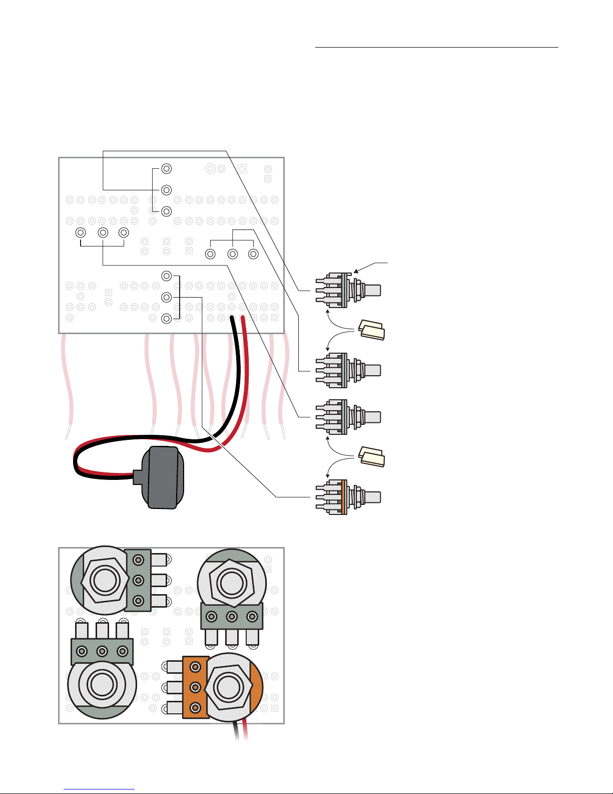
Step 7: Install four control pots
The last components to go onto the circuit board are the four
control pots. They install on the back of the board. Each pot
has three connecting lugs, refer to the below left graphic to
be sure your orientation is correct when installing the pots.
If any pot has an index pin protruding from the case, break
it o before installation, so the pot will mount ush against
the pedal case. Needle nose pliers work well for removing
the pins.
Use the adhesive foam tape to insulate the back of the
pots from the soldered leads of the other parts on the circuit
board. Solder the pot in place, making sure the foam back
sits at the back of the board.
Refer to the left graphic to be sure your orientation is correct
when installing the pots.
B100K
A1M
A1M
A1M
A1MΩ “treble” pot #7459
Apply adhesive foam tape to back of the pots
If the pot has an index pin, break it o.
A1MΩ “bass” pot #7459
A1MΩ “gain” pot #7459
Apply adhesive foam tape to back of the pots
B100KΩ “level” pot #7453

stewmac.com ©2018 StewMac page 10 of 14
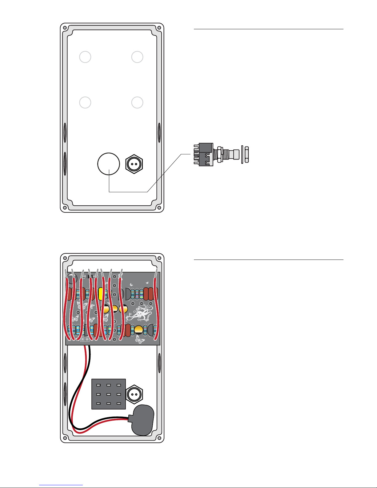
Step 8: Install one LED indicator light
The LED mounting bezel consists of two main parts: A ring
that the LED ts into, and a plastic plug that goes over the
LED from the back side to keep it in place.
Like some of the caps and diodes, the LED is polarized and
has to be installed in a specic direction. One side of the di-
ode has a at edge, indicating the negative lead. Another in-
dication is that the negative lead is shorter than the positive.
Install the mounting bezel through the front of the enclosure.
From the inside, slip a lock washer and nut on and tighten it
up using a 3/8" socket. Insert the LED into the bezel so the
at side (short lead) faces the hole for the footswitch. Feed
the leads through the plastic plug, press the plug down until
it’s tight in the bezel. The LED will be held in place when you
solder the leads to the switches and circuit board. For a more
secure mount, you can run a bead of clear silicone adhesive
around the plastic plug.
5mm LED mounting bezel (1) #7432
5mm white LED (1) #7422
case
stewmac.com ©2018 StewMac page 11 of 14
Step 9: Install one footswitch
Step 10: Install the circuit board
Install the footswitch so the part number printed on the side
faces the bottom of the enclosure. Use a 14mm wrench
to tighten it up. The switch is the eect bypass switch that
turns on the pedal.
The circuit board is held in place by the control pots.
Install their shafts through the top of the case, and thread
washers onto them on the outside. Using a 10mm wrench
install the mounting nuts so they are good and snug, but
take care not to overtighten.
Do not connect any of the lead wires at this point.
3PDT latching footswitch (1) #1611
V–V+ B+ B+ B– B– GO
IGL
.47
.022
.001
.0047
.0022
22K
1M
1M
1 M
10 M
330
220 p
10 M
10 K
10 K
100 p
100
100K
10 K
68K
100p
.01
10K
1K
22 K
470 K
.001
470 p
100u
10
1
1
10
.01
100K
100 K
EarthQuaker Devices
Monarch Rev 2 | 2011
stewmac.com ©2018 StewMac page 12 of 14
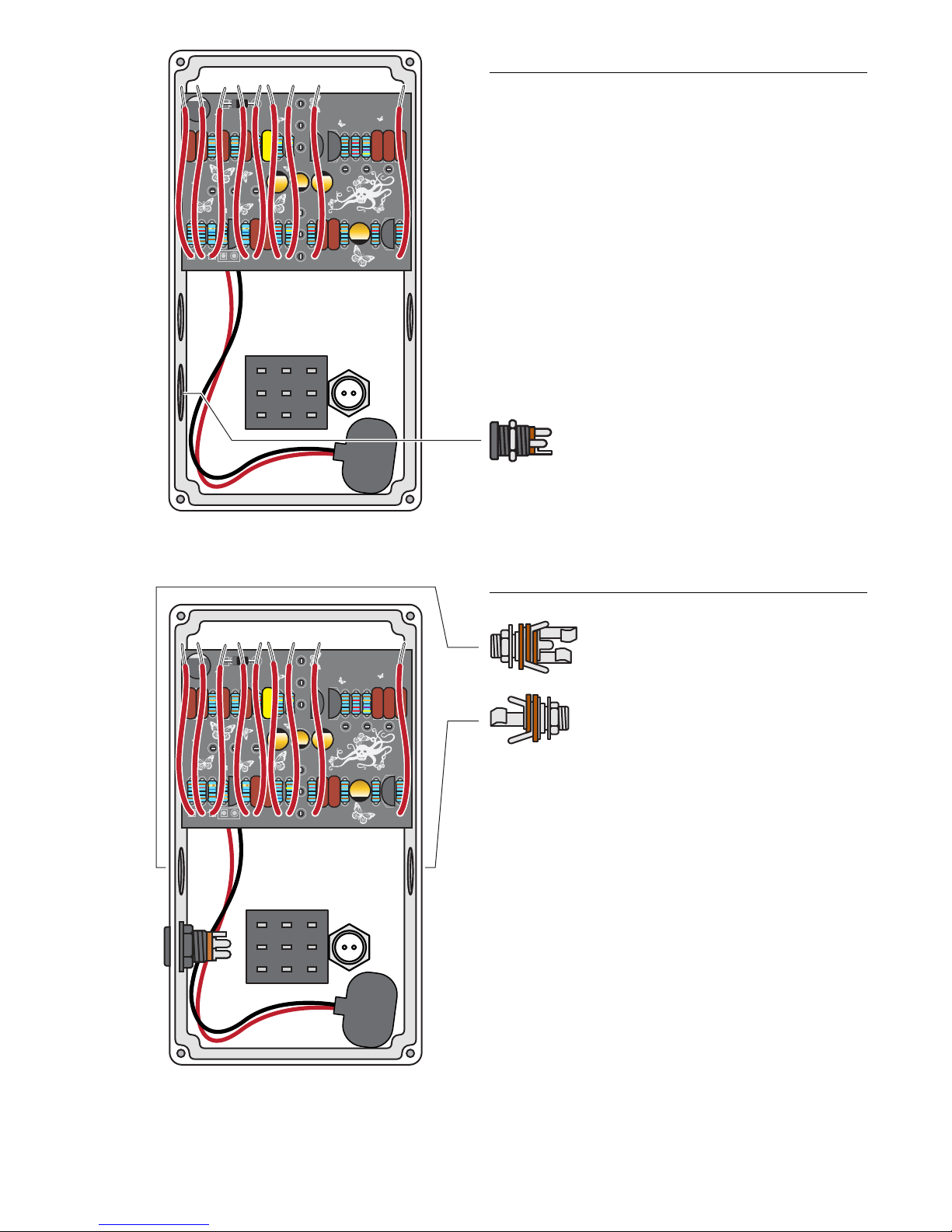
Step 11: Install one DC jack
Install the DC jack using a 14mm wrench.
V–V+ B+ B+ B– B– GO
IGL
.47
.022
.001
.0047
.0022
22K
1M
1M
1 M
10 M
330
220 p
10 M
10 K
10 K
100 p
100
100K
10 K
68K
100p
.01
10K
1K
22 K
470 K
.001
470 p
100u
10
1
1
10
.01
100K
100 K
EarthQuaker Devices
Monarch Rev 2 | 2011
2.1mm DC power connector (1) #7467
Step 12: Install two jacks
V–V+ B+ B+ B– B– GO
IGL
.47
.022
.001
.0047
.0022
22K
1M
1M
1 M
10 M
330
220 p
10 M
10 K
10 K
100 p
100
100K
10 K
68K
100p
.01
10K
1K
22 K
470 K
.001
470 p
100u
10
1
1
10
.01
100K
100 K
EarthQuaker Devices
Monarch Rev 2 | 2011
#4652 Mono jack (1)
#4653 Stereo jack (1)
There are two dierent jacks for this kit, one stereo and
one mono. The stereo jack is the input and the mono is the
output. When looking at the back of the enclosure, the stereo
jack will go on the left side and the mono on the right. Install
the input and output jacks with the solder lugs facing up.
This will make soldering easier later.
Run the 9V battery clip under the jack to keep it out of the
way.
A 1/2" wrench is recommended to tighten the jacks in place.
stewmac.com ©2018 StewMac page 13 of 14
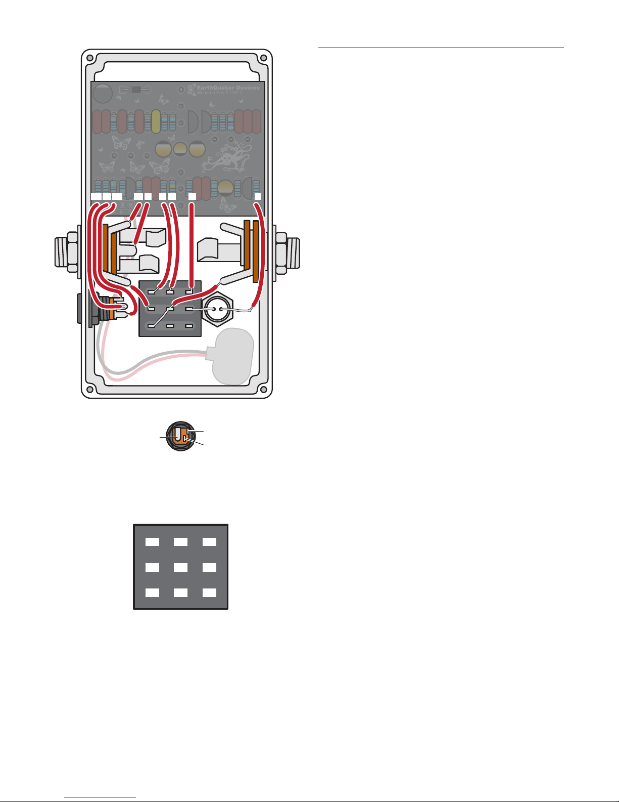
Step 13: Final wire-up
With all of the components in place, it is time to wire it all up.
Starting on the left-hand side of the circuit board, wire up the
DC jack rst. The wire labeled V+ connects to the +9V lug.
V- connects to Masse (GND) lug. B+ connects to Battery + lug.
Next solder the input jack. Solder the wire labeled B- to the
lug that connects to the shorter tip of input jack. This will
disconnect the battery when unplugged. Next solder the
wire labeled G to the sleeve lug on the input jack. This lug
connects to the threaded shaft of the jack.
Continuing, solder the wire labeled I to lug #1 on the foot-
switch. Solder the wire labeled O to lug #4. Finally, solder
the wire labeled G to lug #7.
Solder the nal wire labeled L to the positive (long) lead of
the LED.
Moving on to the footswitch, solder a wire to lug #2 then
solder the same wire to the lug of the input jack that con-
nects to the longer tip. Solder the wire with the 1/4” striped
end to jumper lugs #3 and #5 on the footswitch, then solder
the same wire to the tip lug of the output jack. Finally solder
the negative (shorter) lead of the LED to the #8 lug of the
footswitch.
Add a battery, if you would like. Screw on the back panel
and plug in!
The lugs on the footswitches are
numbered as shown above.
The lugs on the DC jack are as
show above.
1
2
3
4
5
6
7
8
9
V–V+ B+ B+ B– B– GO
IGL
.47
.022
.001
.0047
.0022
22K
1M
1M
1 M
10 M
330
220 p
10 M
10 K
10 K
100 p
100
100K
10 K
68K
100p
.01
10K
1K
22 K
470 K
.001
470 p
100u
10
1
1
10
.01
100K
100 K
EarthQuaker Devices
Monarch Rev 2 | 2011
Masse (GND) lug +9V lug
Battery + lug
V+ B- G O G LV- B+ I
stewmac.com ©2018 StewMac page 14 of 14
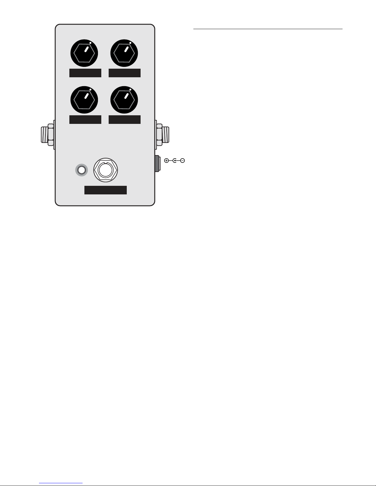
Here’s how the controls work:
Treble: Boosts the highs.
Bass: Boosts the lows.
Gain: Adjusts the amount of drive.
Level: Adjusts the output level, unity is around 9 o’clock…
This thing is LOUD!
Power: Use a standard 9 volt DC power supply with a
2.1mm negative-center barrel (not included). We always
recommend pedal-specic, transformer-isolated wall-wart
power supplies or supplies with separate isolated outputs.
Pedals will make extra noise if there is ripple or unclean
power. Switching-type power supplies, daisy chains and
non-pedal specic power supplies do not lter dirty power as
well and let through unwanted noise. Do not run at higher
voltages! Current draw is 3 mA.
INPUTOUTPUT
9V DC
BASSTREBLE
LEVELGAIN
BYPASS
Other StewMac Music Pedal manuals

StewMac
StewMac JHS 808 User manual

StewMac
StewMac TAPE OP DELAY Manual

StewMac
StewMac SCREAMER Manual

StewMac
StewMac Disaster Transport User manual

StewMac
StewMac FAN TREMOLO Manual

StewMac
StewMac SWELL DRIVE Manual

StewMac
StewMac SUN FUZZ Manual

StewMac
StewMac INTERVAL FUZZ Manual

StewMac
StewMac NYC BIG MUFF PI User manual

StewMac
StewMac TWO KINGS BOOST DOUBLE-POWERED ROYAL TONE Manual


