Electric Mirror QUANTUM User manual
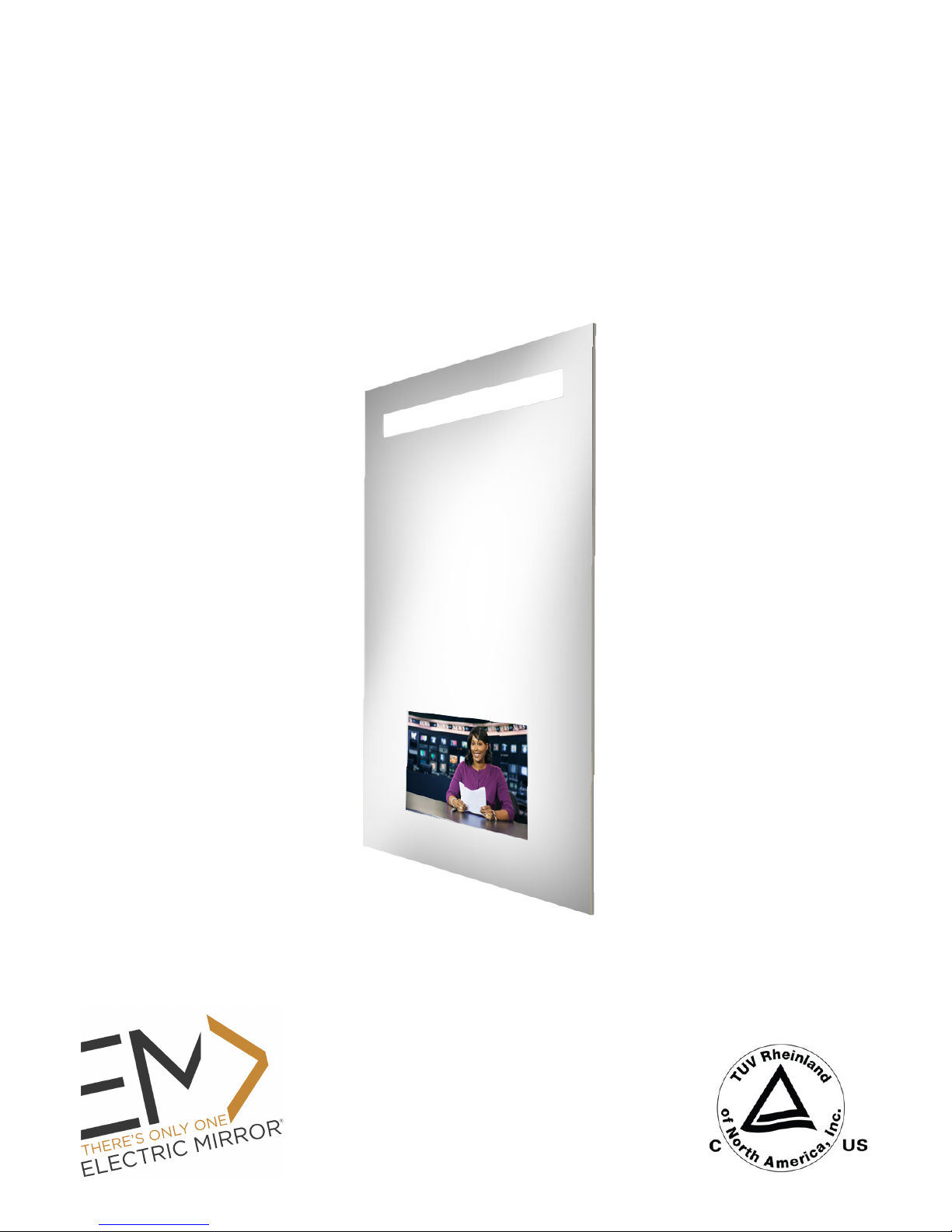
QUANTUM™
LIGHTED MIRROR TV
Installation Instructions
IMPORTANT SAFETY INSTRUCTIONS
Must be installed by a qualified technician.
Read these installation instructions. Keep these instructions for future use. Follow all instructions. Install in
accordance with manufacturer’s instructions.
FAILURE TO FOLLOW INSTRUCTIONS COULD RESULT IN DEATH OR SERIOUS BODILY HARM.
FAILURE TO FOLLOW INSTRUCTIONS VOIDS WARRANTY.
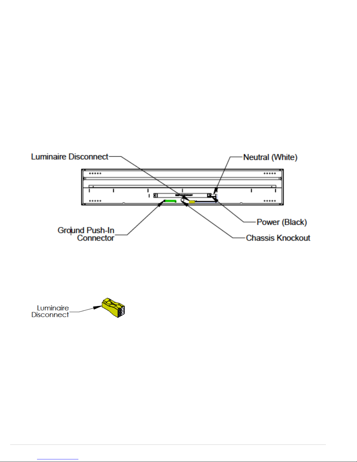
This luminaire must be mounted or supported independently of an outlet box. Make sure electrical connections
are wired correctly. Power and neutral wires must be connected to the luminaire disconnect. Insert the power
wire into the black colored insert and the neutral wire into the white colored insert.
The ground must be connected. Do not defeat the safety purpose of the grounding wire
inside the chassis. The chassis must be grounded to avoid possible electrical shock.
CAUTION
READ ALL INSTRUCTIONS PRIOR TO INSTALLATION
WARNING:
TO PREVENT INJURY, THE MIRROR MUST BE INSTALLED IN ACCORDANCE WITH THE MANUFACTURER’S
INSTRUCTIONS
CAUTION
THE ONLY USER-SERVICEABLE PARTS INSIDE ARE THE LAMPS.
OTHER COMPONENTS MUST BE SERVICED BY QUALIFIED ELECTRICIANS/PERSONNEL. LUMINAIRE
DISCONNECT MUST BE DISCONNECTED PRIOR TO COMPONENT SERVICING.
2THERE’S ONLY ONE™ ELECTRIC MIRROR® | E sales@electricmirror.com | T +1 425 776-4946 | F +1 425-491-8200 | W www.electricmirror.com
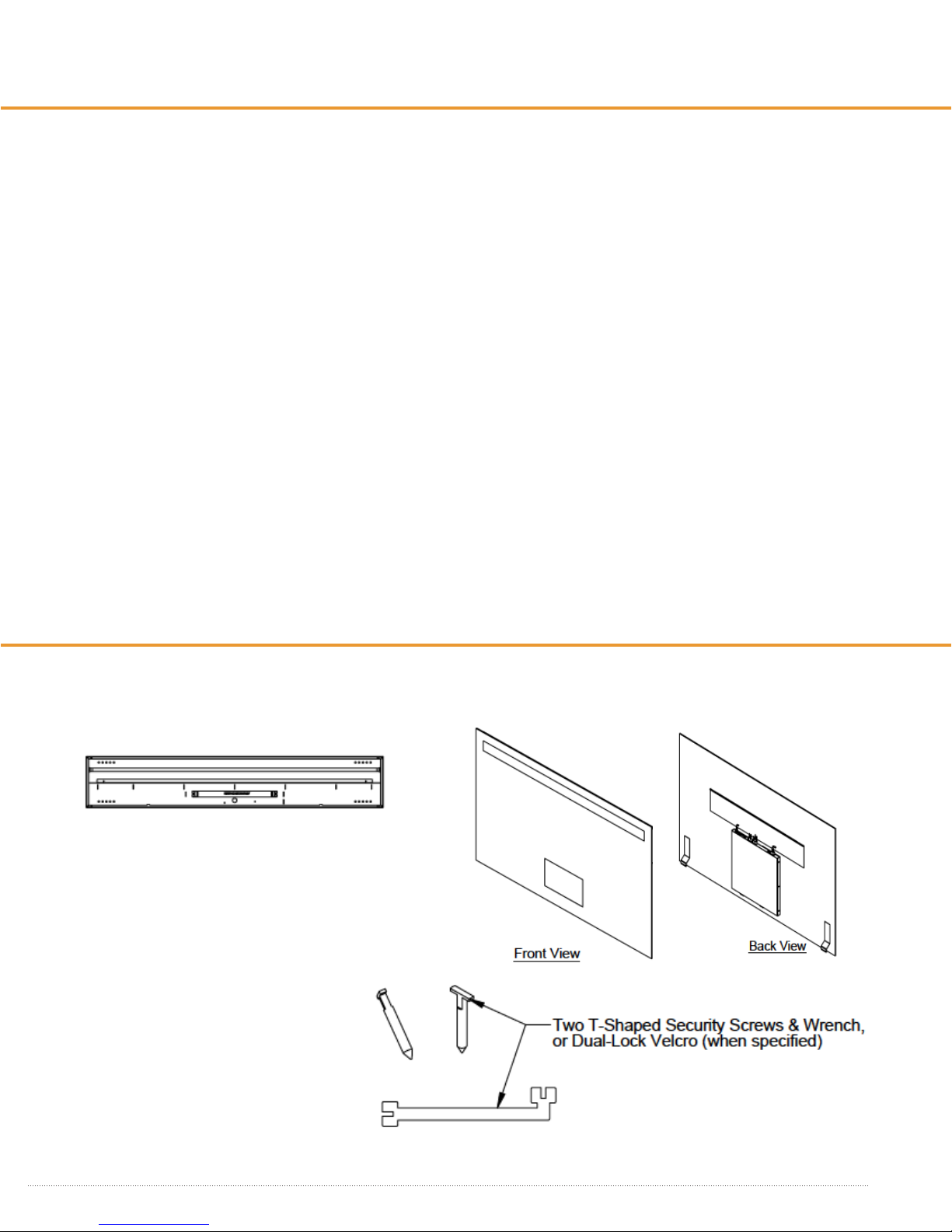
UNPACKING YOUR MIRROR TV
Verify Contents
Prior to installation, unpack items and verify contents. The lighted mirror comes with 3 boxes and lamps:
BOX 1: CHASSIS ASSEMBLY BOX 2: MIRROR ASSEMBLY WITH INTEGRAL HANGERS
BOX 3: KIT-TV-XX
Includes remote, power cord, RF cable, & optional speakers
3
THERE’S ONLY ONE™ ELECTRIC MIRROR® | E sales@electricmirror.com | T +1 425 776-4946 | F +1 425-491-8200 | W www.electricmirror.com
INSTALLATION
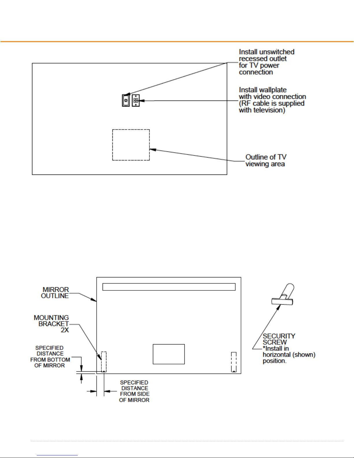
1. WALL PREPARATION
Ensure that a recessed power receptacle and a video 4-port wall plate are installed behind the mirror. For the
United States and Canada, the recessed receptacle may need to be on a GFCI circuit. (Please check your local
jurisdiction for projects outside the United States or Canada.) The recessed receptacle and 4-port plate should be
placed within the referenced dimensions from the Sales Aid. Use a mud ring, in combination with the 4-port plate
for AV connections. The Mirror TV comes with RF cable, HDMI, S-Video, VGA, and Component video connections.
Please consult your AV specialist for which video connection is necessary for your project. In instances where the
TV may be at the top of the mirror, please see a separate specification for this custom application.
2. MOUNTING BRACKETS
Mark security screw locations for mounting brackets and install. Use flat wrench provided to turn screws. Make
sure the screws are installed in horizontal position. In some installations, such as with a tile wall, it may be dicult
to install security screws; in these cases, when specified in advance, Dual-lock Velcro will be already attached to
the bottom mirror security bracket.
4THERE’S ONLY ONE™ ELECTRIC MIRROR® | E sales@electricmirror.com | T +1 425 776-4946 | F +1 425-491-8200 | W www.electricmirror.com
5. WIRING DETAILS
Please note, all electrical installations should be carried out by a fully qualified electrician in conformance with
the National Electrical Code and local building codes.
Power supply connection. Before proceeding to power supply wiring, make sure the MC cable is brought in
through the wall and into the chassis knockout.
Insert ground wire in the grounded connector. Insert the power and neutral wires into the luminaire disconnect.
The power wire is inserted into the black port (number 1) and the neutral wire is inserted into the white port
(number 2).
3. MOUNTING CHASSIS ON THE WALL
Before mounting chassis on wall, identify mirror location on wall. Drill marks should be measured from the edge of
the mirror NOT FROM EDGE OF CHASSIS.
There are multiple mounting holes that can be chosen from to accommodate mounting locations. The chassis
shall be installed with a minimum of (4) 1/4” x 1-1/2” lag screws or other engineering approved fasteners. Use wall
anchors or reinforced backing areas to support chassis. See individual product specifications for mounting hole
locations.
4. INSTALL LAMPS
Lamps should fit within the lamp holders provided in chassis. Rotate lamps to lock into place.

5
THERE’S ONLY ONE™ ELECTRIC MIRROR® | E sales@electricmirror.com | T +1 425 776-4946 | F +1 425-491-8200 | W www.electricmirror.com
Power up the TV unit and test audio and video functionality. The LCD TV operates by remote control only. Take
the batteries out of the remote. Remove the safety tab, place the batteries back inside and close. Turn TV on. Hit
the source button to search for RF source. Hit the scan button to auto scan the TV to cable channel. Refer to the
TV Operation Manual for instructions on how to operate the TV.
6. TV CONNECTIONS
Connect Power and Video. Move the Mirror TV close to the final position and plug the power, video, and audio
cables (from the integrated mini-speakers) into their appropriate sources. An RF cable is provided. Before hanging
the unit, ensure that cables have sucient slack.
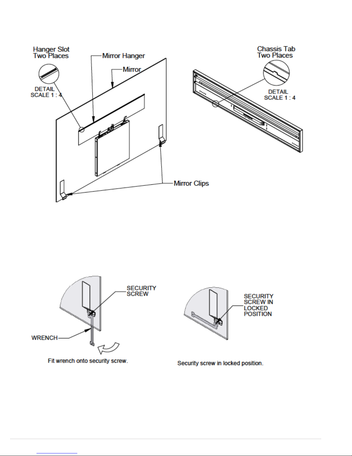
7. MIRROR MOUNTING
After the wiring process is complete, the mirror is ready to be hung on the chassis. The weight of the mirror is
supported at the top of the chassis. The chassis flange, at the bottom of mirror, is used to keep the mirror from
moving away from the wall.
Hang the mirror on the chassis by aligning the tabs on the chassis with the mirror hanger slots while holding the
mirror against the chassis. Slide the mirror down, inserting the chassis tabs into the hanger slots. Make sure both
tabs are engaged through hanger slots and the mirror clip overlaps the chassis flange.
6THERE’S ONLY ONE™ ELECTRIC MIRROR® | E sales@electricmirror.com | T +1 425 776-4946 | F +1 425-491-8200 | W www.electricmirror.com
Table of contents
Other Electric Mirror TV manuals


