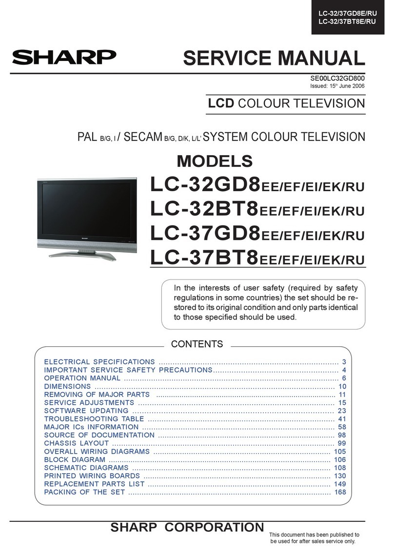
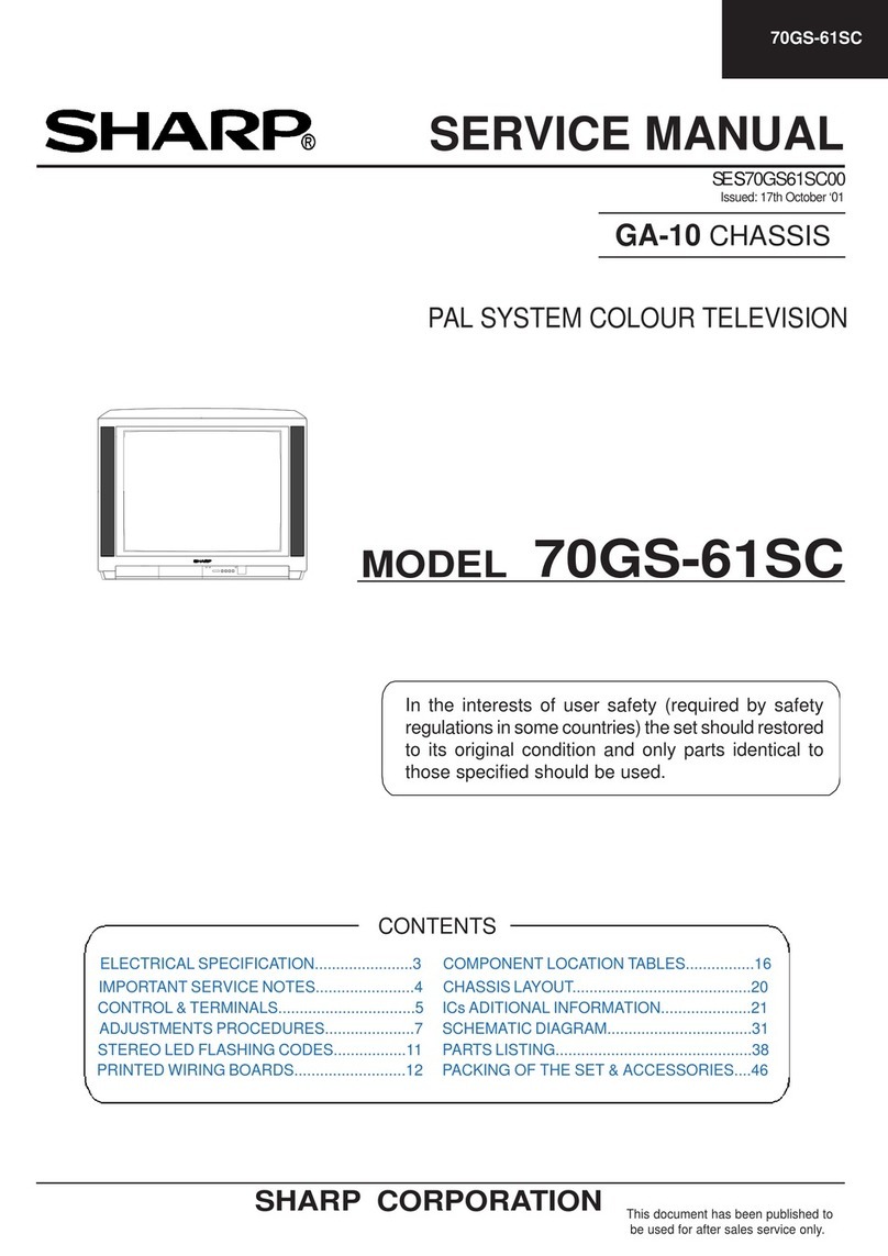
Sharp LC-12A2E User manual

1
LC-12A2E
S00J8LC-12A2E
LCD COLORTELEVISION
SERVICE MANUAL
MODEL LC-12A2E
In the interests of user-safety (Required by safety regula-
tions in some countries) the set should be restored to its
original condition and only parts identical to those specified
be used.
Page
»IMPORTANT SERVICE SAFETY PRECAUTION................................................................................. 2
»ELECTRICAL SPECIFICATIONS......................................................................................................... 3
»OPERATION MANUAL ......................................................................................................................... 4
»OUTLINE DIMENSION FIGURE .......................................................................................................... 5
»DISASSEMBLY OF THE SET............................................................................................................... 6
»ADJUSTING PROCEDURE OF EACH SECTION ............................................................................... 8
»TROUBLE SHOOTING TABLE ........................................................................................................... 11
»CHASSIS LAYOUT ............................................................................................................................. 14
»BLOCK DIAGRAM .............................................................................................................................. 16
»DESCRIPTION OF SCHEMATIC DIAGRAM ..................................................................................... 18
»SCHEMATIC DIAGRAMS ................................................................................................................... 19
»PRINTED WIRING BOARD ASSEMBLIES........................................................................................ 26
»PARTS LIST
ËELECTRICAL PARTS..................................................................................................................... 31
MAIN UNIT ..................................................................................................................................... 31
TERMINAL UNIT............................................................................................................................ 35
SWITCH UNIT................................................................................................................................ 37
R/C UNIT........................................................................................................................................ 37
ËSUPPLIED ACCESSORIES PARTS.............................................................................................. 38
ËPACKING PARTS ........................................................................................................................... 38
ËCABINET PARTS LIST................................................................................................................... 38
ËCABINET AND MECHANICAL PARTS.......................................................................................... 39
»PACKING OF THE SET ...................................................................................................................... 40
CONTENTS
SERVICE MANUAL LCD COLOR TELEVISION MODEL LC-12A2E
SHARP CORPORATION

LC-12A2E
2
1234567890123456789012345678901212345678901234567890123456789012123456789012345678901234567890121234
1
23456789012345678901234567890121234567890123456789012345678901212345678901234567890123456789012123
4
1234567890123456789012345678901212345678901234567890123456789012123456789012345678901234567890121234
1234567890123456789012345678901212345678901234567890123456789012123456789012345678901234567890121234
1
23456789012345678901234567890121234567890123456789012345678901212345678901234567890123456789012123
4
1
23456789012345678901234567890121234567890123456789012345678901212345678901234567890123456789012123
4
1234567890123456789012345678901212345678901234567890123456789012123456789012345678901234567890121234
SAFETY NOTICE
Many electrical and mechanical parts in LCD television
have special safety-related characteristics.
These characteristics are often not evident from visual
inspection, nor can protection afforded by them be
necessarily increased by using replacement components
rated for higher voltage, wattage and etc.
Replacement parts which have these special safety
characteristics are identified in this manual; electrical
components having such features are identified by “ å”
IMPORTANT SERVICE SAFETY PRECAUTION
ËService work should be perfomed only by qualified service technicians who are thoroughly
familiar with all safety checks and the servicing guidelines which follow:
and shaded areas in the
Replacement Parts Lists
and
Schematic Diagrams
.
For continued protection, replacement parts must be
identical to those used in the original circuit.
The use of a substitute replacement parts which do not
have the same safety characteristics as the factory
recommended replacement parts shown in this service
manual, may create shock, fire or other hazards.
WARNING
1. For continued safety, no modification of any circuit
should be attempted.
2. Disconnect AC power before servicing.
BEFORE RETURNINGTHE RECEIVER
(Fire & Shock Hazard)
Before returning the receiver to the user,perform the
following safety checks:
1. Inspect all lead dress to make certain that leads are not
pinched, and check that hardware is not lodged between
the chassis and other metal parts in the receiver.
2. Inspect all protective devices such as non-metallic
control knobs, insulation materials, cabinet backs,
adjustmentandcompartmentcovers or shields,isolation
resistor-capacitor networks, mechanical insulators, etc.
3. Tobesure that no shockhazard exists, checkforleakage
current in the following manner.
• Plug the AC cord directly into a 110~240 volt AC outlet,
and connect the DC power cable into the receiver's DC
jack.(Do not use an isolation transformer for this test).
• Usingtwoclipleads,connecta 1.5k ohm, 10wattresistor
paralleled by a 0.15µF capacitor in series with all
exposed metal cabinet parts and a known earth ground,
such as electrical conduit or electrical ground connected
to earth ground.
• Use an AC voltmeter having with 5000 ohm per volt, or
higher,sensitivity or measure the ACvoltagedrop across
the resisor.
• Connect the resistor connection to all exposed metal
parts having a return to the chassis (antenna, metal
cabinet, screw heads, knobs and control shafts,
escutcheon and etc.) and measure the AC voltage drop
across the resistor.
All checks must be repeated with the AC cord plug
connection reversed. (If necessary, a nonpolarized
adaptor plug must be used only for the purpose of
completing these checks.)
Any reading of 0.75V peak (this corresponds to 0.5
milliamp. peak AC.) or more is excessive and indicates
a potential shock hazard which must be corrected before
returning the monitor to the owner.
TO EXPOSED
METAL PARTS CONNECT TO
KNOWN EARTH
GROUND
DVM
AC SCALE
50k ohms.
10W
0.15 µF
TEST PROBE
CAUTION
FOR CONTINUED PROTECTION
AGAINST A RISK OF FIRE REPLACE
ONLY WITH SAME TYPE FUSE.
F3701 (1.25A, 250V), F3702 (1.25A, 250V),
F3751 (2A, 250V) FUSE.
3
LC-12A2E
ELECTRICAL SPECIFICATIONS
Items ................................................................12" LCD COLOR TV, Model: LC-12A2E
LCD panel.................................................................................................. 12" TFT LCD
Number of pixels ........................................................................................ 921,600 dots
Video color system ..........................................................................PAL/NTSC/SECAM
TV FUNCTION
TV Standard (CCIR) .............................................................................. BG/DK/I/L/L'
TV Tuning System.......................................................................Auto preset 100 ch.
STEREO/BILINGUAL ............................................................................NICAM, IGR
AUTO PRESET.................................................................................................... Yes
CATV.....................................................................................................~Hyper Band
Brightness....................................................................................................... 400 cd/m2
Lamp life ....................................................................................................60,000 hours
Viewing angles........................................................................................H: 160°V: 160°
Audio amplifier ............................................................................... 0.6 W ×2, 2.5 W ×1
Speakers........................................................................3 ×4 cm 2 pcs., 65 mm φ 1 pc.
Terminals
AV1 ................................................................. AV-IN1, S-VIDEO-IN, COMPONENT
AV2 ...................................................................................................AV-IN2/AV OUT
ANTENNA............................................................................................................DIN
HEADPHONE .......................................................................... 3.5 mm φ jack (Rear)
OSD language ........................English/German/Dutch/French/Italian/Spanish/Swedish
Power requirement................................................... DC 12V, AC 110 - 240 V, 50/60 Hz
Weight ................................................................... 3.0 kg, incl. stand, excl.accessories
Accessories ......................................................... R/C, Batteries, AC adapter, AC cord,
Operation manual, Cable clamp
Specifications are subject to change without prior notice.

LC-12A2E
4
OPERATION MANUAL
Power/standby indicator
A green indicator lights when the power is on and a red indicator
lights when in the standby mode (the indicator will not light when
the main power is off).
Rear control panel
Remote sensor window
(The actual location is not visible)
To change the angle of the TV
set, tilt the screen 10 degrees
forward or 20 degrees backward.
It can also be rotated 90 degrees.
Please adjust the angle so that
the TV set can be watched most
comfortably.
Main unit (front view) Main unit (rear view)
Remote control

5
LC-12A2E
OUTLINE DIMENSION FIGURE
Unit: mm

LC-12A2E
6
DISASSEMBLY OFTHE SET
1. Insert your finger into the center of the terminal cover
and pull it toward you to detach the terminal cover.
2. Remove the four screws 1and one screw 2.
3. Open the cabinet B by approx.45˚ from the bottom
of the cabinet (stand side).
4. Remove the lead wire from the cable clamp 3.
5. Remove the power connector 4.
6. Remove the connector 5from the light reception
unit.
7. Remove the lead wire from the cable clamp 6.
8. Remove the speaker connector 7.
9. Remove the FFC from the FFC connector 8on the
main PWB.
10. Remove the connector 9from the ir unit.
11. Remove the connector 0from the switch PWB.
12. Remove the right and left speaker connectors q
on the terminal PWB.
<<Disassembly of the main PWB>>
1. Disconnect the flexible cable connectors wand
efrom the LCD panel.
2. Disconnect the cable connectors rand tfrom
the fluorescent lamp.
3. Remove the four screws y.
<<Disassembly of the terminal PWB>>
1. Remove the cover i.
2. Remove the five screws u.
3. Remove the two screws o.Take them out of the
cabinet holes.
<<Cabinet A side>>
<<Cabinet B side>>
Cabinet A GCABA2401CEKB
Terminal Cover GCOVA1855CEKB
Hinge Cover GCOVA1853CESA
Rotation Cover GCOVA1854CESA Cabinet B GCABB2295CEKA

7
LC-12A2E
• Caution for handling the LCD panel
1. Work in a clean room. (Humidity: 50% or more)
2. A worker must wear arm bands.
3. Work on a conductive mat.
4. Do not expose the unit to shock such as fall or
vibration.
<<Disassembly of LCD Panel>>
1. Remove the six LCD unit fixing screws.
2. Remove the shield case.
3. Remove the light guide plate holder.
4. Remove the reflection panel.
5. Remove the light guide plate lamp unit.
6. Remove the light guide plate.
7. Remove the lamp unit.
8. Remove the fixing angle.
9. Remove the ITO sheet, diffusion sheet and
reflection polarizing sheet.
1
1
1
3
2
4
5
6
7
8
9
LCD Display Unit
Reflection Polarising Sheet
Spacer
Spacer
Fixing Angle
Shield Case
Light Guide Plate Holder
Reflection Panel
Lamp Unit
(KLMP-0096CEZZ)
Light Guide Plate
ITO Sheet
Diffusion Sheet

LC-12A2E
8
ADJUSTING PROCEDURE OF EACH SECTION
Preparation for Adjustments
Use the dedicated AC adapter or stable DC power supply.
AC adapter: UADP-0210CEZZ
DC power supply: 12 (V), 3.2 (A)
[1] Adjusting procedure
1-1. Checker adjustment
Power ON (initialization) →Setting of model and inch size →Model data transfer to the setting E2PROM (I2C) →
Adjustment processing mode →Adjustment (+B adjustment, 38.9-VCO adjustment, 33.9-L’-VCO adjustment,
RF-AGC cut-in adjustment)
1-2. Finish processing adjustment
Setup →Power ON →Adjustment processing mode (Remote control) →Opposed bias, TV contrast and white
balance adjustments
[2] Entering the adjustment processing mode
• Setting the 81 pin (KEY4) or 82 pin (KEY5) of IC2001 (microcomputer) to “L”, turn on the power.
[3] Key operation in the adjustment processing
Selection of the receiving channel
• The receiving channel UP/DOWN is performed with the tuning UP/DOWN key.
One push ...The UP/DOWN tuning is performed per channel.
Continuous push ...The UP/DOWN search is performed until a next receivable station is found.
• Various adjustments
The adjustment is performed for each item by the menu select, tuning UP/DOWN or volume UP/DOWN key (main
body and remote control).
• The adjustment item makes a toggle operation with the menu select key input.(Next item)
If the menu select key is input while the bottom item is selected, it moves to the top item on the next page.
• The adjustment item makes a toggle operation with the video select key input.
(Previous item) If the video select key is input while the top item is selected, it moves to the bottom item on the
previous page.
• If the auto preset key is input while an item is selected, it moves to the top item on the next page.
Page 1 →Page 2 →... →Page 15 →Page 1
• If the manual memory key is input while an item is selected, it moves to the top item on that page.UP/DOWN of each
adjustment vale selected is performed with the volume UP/DOWN key input.
• For P14 – 15, the unit enters the register select mode with the volume UP/DOWN key input while PAL/NTSC is
selected, and the cursor moves to the address 01.
• The cursor moves up or down with the tuning UP/DOWN key and moves left or right with the volume UP/DOWN key,
and a decision is made with the 12 key.
When the decision is made, the cursor moves to the adjustment value selected, and UP/DOWN of each adjustment
value selected by the volume UP/DOWN key input is performed.
Decide with the 12 key and return to the address select.Move to the next item with the menu select key.
During address select, the cursor movement by the volume UP/DOWN key input is as follows:
Example: 01 ↔02 ↔03 ↔01 ↔...
The cursor movement by the tuning UP/DOWN key input is as follows:
Example: 02 ↔05 ↔... ↔F6 ↔02 ↔...

9
LC-12A2E
[4] Initialization
4-1. Connect the 81 pin and 82 pin of IC2001 (microcomputer) to GND, and turn on the power.
4-2. Select the model name (A2E/A2E(K)).
4-3. Select the inch size (12).
4-4. Return the 81 pin and 82 pin of IC2001 (microcomputer) to the original state.
[5]Transmission data by model
Transmission data
[6] Adjustment
6-1. +B adjustment
1) Receive the E-12CH (PAL color bar).
2) Adjust the voltage of the 49 pin of SC401 to 5.00V±0.02V.
Note: Since 5.0V is a reference voltage of all power voltage, adjust it precisely.
6-2. 38.9-VCO adjustment
1) Set the sound system to the B/G mode.
2) Send the CW signal of 38.9MHz, 90dBµV from SG to TP3201 (IF-OUT).
3) Adjust the L3231 coil so that a voltage of 2.5±0.2V is obtained at TP3203 (AFT).
Note 1:The input impedance of the digital voltmeter must be 1MΩor more.
Note 2:To adjust L3231, use a non-magnetic driver.
Note 3: No signal must not be input from the antenna.
6-3.33.9-L’-VCO adjustment
1) Set the sound system to the L’ mode.
2) Send the CW signal of 33.9MHz, 90dBµV from SG to TP3201 (IF-OUT).
3) Adjust the R3233 volume so that a voltage of 2.5±0.2V is obtained at TP3203 (AFT).
Note 1:The input impedance of the digital voltmeter must be 1MΩor more.
Note 2: After performing the adjustment of the item 6-2, execute this item.
Note 3: No signal must not be input from the antenna.
6-4.RF-AGC cut-in adjustment
1) Set the sound system to the B/G mode, and receive the E-12CH (PAL color bar).
2) Set the antenna input level to 56dBµV (75Ωtermination, QP value).
3) Turn the R3231 (AGC volume) clockwise so that the voltage of the TP3202 (RF-AGC terminal) becomes
maximal.
4) Turn it counterclockwise, and adjust the AGC terminal voltage to the point that is lower than the maximal
voltage by 0.5±0.2V.
6-5. Opposed bias adjustment
1) Receive the monoscope pattern.
2) Adjust the "COM BIAS" so that the contrast of the stairway-shaped part may become the biggest.
Model E2PROM adress Item Write Data OSD Display

LC-12A2E
10
6-6.TAMP adjustment
1) Receive the E-12CH (PAL color bar).
2) If the reading of “Y” on the page 2 of the adjustment processing is not located between B0 and BA, perform
the adjustment of “PAL TAMP” on the same page so that the reading of “Y” is located between B0 and BA.
3) If the adjustment of “PAL TAMP” is executed, write its adjustment value to the followings manually.
“NTSC TAMP”
“SECAM TAMP”
“PAL.M TAMP”
“PAL.N TAMP”
(Screen of the page 2 of the adjustment processing menu OSD)
0 1 2 3 4 5 6 7 8 9 10 11 12 13 14 15 16 17 18 19 20 21 22 23 24 25 26
2COM B I AS 1 1 7
NTSC TAMP 27
PAL TAMP 27
SECAM TAMP 27
PAL -M TAMP 27
PAL - N TAMP 27
TV H - PEAK ING 3
RCU TOF F +3
GCU TOF F 0
BCUTOF F - 9
G3 B3 R3 00 00 00
G1 B4 Y 0 0 00 B5
0
1
2
3
4
5
6
7
8
9
10
11
12
13
Y Data
(White 75%)
3)
Item
6-7.White balance adjustment
1) Receive the monoscope pattern.
2) Adjust “RCUTOFF” and “BCUTOFF” on the page 2 of the adjustment processing so as to obtain the color of
the same level as the standard set.
Caution: For the adjustment processing of “RCUTOFF” and “BCUTOFF”, adjust them in the indication value
range of –10 ~ +10.

11
LC-12A2E
TROUBLE SHOOTINGTABLE
No picture
at all
Yes
No
Are inputs
and outputs
of IC802 as
specified?
Check all the settings on the microprocessor’s adjust process menu.
No picture
Check IC802
and its
peripheral
parts.
Yes
No
Are inputs
and outputs
of IC1201 as
specified?
Check
IC1201 and
its peripheral
parts.
Check LCD
panel voltage
and
waveform.
NoTV and
VIDEO 1
output
Yes
No
Are inputs
and outputs
of IC402 as
specified?
Check IC402
and its
peripheral
parts.
No
Is input at Pin
(73) of IC802
as specified?
Check IC802,
AV1 line and
their
peripheral
parts.
NoTV
output
Yes
No
Are voltages
at Pins (6),
(7) and (9) of
tuner as
specified?
Check the
power line.
Yes
No
Is output at
Pin (19) of
tuner as
specified?
Check the
tuner and its
peripheral
parts.
No
Is input at Pin
(1) of IC402
as specified?
Check the
line in
question.
Yes
Check IC402
and its
peripheral
parts.
Yes
No
Are Pins (2)
and (4) of
IC402 at “H”
and “L”
respectively?
Are Pins (65)
and (66) of
IC2001 at “H”
and “L”
respectively?
NoVIDEO
1 output
Yes
No
Is input at Pin
(1) of IC402
as specified?
Check the
line in
question.
Yes
No
Are Pins (2)
and (4) of
IC402 both at
“L”?
No
NoVIDEO
2 output
No
Is input at Pin
(74) of IC802
as specified?
Check J3409,
AV2 line and
their
peripheral
parts.
No S
VIDEO
output
No
Are inputs at
Pins (71) and
(72) of IC802
as specified?
Check
SC3301, SY
line, SC line
and
peripheral
parts.
No
COMPONENT
output
No
Is input at
Pins (4), (5),
(6) and (75)
of IC802 as
specified?
Check J3404,
J3405, J3406,
DVD-Y line,
CB line, CR
line and
peripheral
parts.
Are Pins (65)
and (66) of
IC2001 both
at “L”?
Check IC402
and its
peripheral
parts.
Yes
Yes
Yes
Yes
Check the
line in
question.
Are data
signal at pins
(31)~(57) of
IC802 as
specified?
Check data
signals at
pins (13),
(14) of IC802.
No
Are input and
output of
IC1201 as
specified?
Yes
Check the
wire breaks
and the short
of circuits of
IC802.
IC1201 and
its peripheral
parts.
Check the
wire breaks
and the short
of circuits of
IC1201 and
its peripheral
parts.
Yes
Check the
line in
question.
Yes
Are input and
output of
IC1201 as
specified?
No
Are data
signals at
pins (31)~(57)
of IC802 as
specified?
No No
Check data
signals at
pins (13), (14)
of IC802.
Yes
Check the
wire breaks
and the short
of circuits of
IC802,
IC1201 and
its peripheral
parts.
Check the
wire breaks
and the short
of circuits of
IC1201 and
its peripheral
parts.
1
Yes
2
1
Yes
Are input and
output of
IC1201 as
specified?
No
Are data
signals at
pins (31)~(57)
of IC802 as
specified?
Check data
signals at
pins (13), (14)
of IC802.
Yes
Check IC802,
IC1201 and
its peripheral
parts.
Check the
wire breaks
and the short
of circuits of
IC1201 and
its peripheral
parts.
2

LC-12A2E
12
TROUBLE SHOOTINGTABLE (Continued)
No picture and sound
No color
NoTV color No S-VIDEO color
Yes
No
Do F3701 and F3702
function?
No
Yes
No
Check all the settings on the microprocessor’s adjust process menu.
No
Are secondary outputs
(+38V, +16V, +9V, +5V, -8V)
of T701 as specified?
Yes
Are the oscillation waveform
at T701’s primary side as
specified?
Yes
No
Disconnect F3701 and
F3702. Is the load side
short-circuited?
Yes
No
Is any of T701’s primary side,
Q701, Q710 and S4701
short-circuited?
Check J3701, its peripheral
parts and connection cable.
Replace F3701 and F3702.
Check S4701 and
connection cable.
Check the secondary-side
load of T701.
Fluorescent lamp
Yes
No
Does F3751 function?
Yes
No
Is Pin (34) of IC1201 at “H”?
Yes
Yes
No
Are the oscillation waveforms
at the primary side ofT751
and T752 as specified?
Yes
Replace F3751.
No
Is input at Pin (71) of IC802
as specified?
Check SC3301, SC line and
peripheral parts.
No
Are data signals at pins
(31)~(57) of IC802 as
specified?
Check each DC pin voltages
of IC802 and its peripheral
parts.
Check input and output
signals of IC1201.
Check the line, IC1201 and
its peripheral parts.
Check Q751, Q752,T751,
T752, Q753 and their
peripheral parts.
Replace the fluorescent lamp
and check the oscillation
waveform again.
NoVIDEO color
Check all the settings on the microprocessor’s adjust process menu.
No COMPONENT color
No
Is input at Pins (4) and (6) of
IC802 as specified?
Check J3404, J3405, CB line,
CR line and peripheral parts.
Yes
Are data signals at
pins (31)~(57) of
IC802 as specified?
Check input and
output signals of
IC1201.
No
Check each DC
pin voltages of
IC802 and its
peripheral parts.

13
LC-12A2E
TROUBLE SHOOTINGTABLE (Continued)
No sound
from front
speakers
Yes
No
Is Pin (53) of
IC2001 at “L”?
No sound
from rear
speakers
Check all the settings on the microprocessor’s adjust process menu.
No sound
No
Are outputs at
Pins (1) and (7)
of IC903 as
specified?
Yes
No
Are inputs and
outputs of
IC303 as
specified?
Yes
No
Are inputs at
Pins (5) and (8)
as well as
outputs at Pins
(2) and (11), all
of IC301, as
specified?
Muting effect is
on. Check the
FSMU line.
Check IC901,
IC903 and their
peripheral
parts.
Check IC303
and its
peripheral
parts.
Check the line
in question,
IC303 and its
peripheral
parts.
Yes
Check the
speakers and
their peripheral
parts.
No sound
from
headphone
Yes
No
Is Pin (55) of
IC2001 at “L”?
Check the
headphone and
its peripheral
parts.
Check Q306,
J3410 and their
peripheral
parts.
Yes
No
Is Pin (54) of
IC2001 at “L”?
No
Are input at Pin
(5) as well as
output at Pin
(2) of IC302, as
specified?
Yes
Check the
speaker and its
peripheral
parts.
Check the line
IC901, IC303
and their
peripheral
parts.
Muting effect is
on. Check the
FSMU line.
No sound
from output
line
Yes
No
Is Pin (52) of
IC2001 at “L”?
No
Are outputs at
Pins (1) and (7)
of IC902 as
specified?
Yes
Check the line
in question.
Check the
LMUTE line.
Check IC902
and its
peripheral
parts.
TV sound
failure
Yes
No
Is output at Pin
(46) of SC3401
as specified?
No
Is input at Pins
(36), (37) of
IC901 as
specified?
Check the
tuner and its
peripheral
parts.
Check IC901,
Q3204, Q3205
and their
peripheral
parts.

14
LC-12A2E
A
B
C
D
E
F
G
H
I
J
12345678910
CHASSIS LAYOUT
MAIN Unit (Side-A)
MAIN Unit (Side-B)

15
LC-12A2E
A
B
C
D
E
F
G
H
I
J
12345678910
TERMINAL Unit
SWITCH Unit
R/C Unit

1234567891011 12 13 14 15 16 17 18 19 20
A
B
C
D
E
F
G
H
I
J
LC-12A2E LC-12A2E
16~17
BLOCK DIAGRAM

18
LC-12A2E
DESCRIPTION OF SCHEMATIC DIAGRAM
1. When the exclusive-use AC adapter is used, the color
bar signal of color bar generator for service is input
to get the normal screen. When the audio is
minimized, the voltage value is measured with the
20 kΩ/V tester.
2. When the exclusive-use AC adapter is used, the color
density, lightness and color hue are set to the center
position, and the signal of color bar generator for
service is observed to get waveform.
The wave form test point is indicated with the mark
( ) in the wiring diagram.
3. Indication of resistors and capacitors
[Resistors]
Unit : Nonindication … Ω, K…kΩ,
M…MΩ
Error : Nonindication … ±10%
J…±5%
F…±1%
D…±0.5%
[Capacitor]
Unit :Nonindication or µ…µF,
P or p … pF
IMPORTANT SAFETY NOTICE:
PARTS MARKED WITH
"å"( )
ARE
INPORTANT FOR MAINTAINING THE SAFETY OF
THE SET.
BE SURE TO REPLACE THESE PARTS WITH
SPECIFIED ONES FORMAINTAININGTHE SAFETY
AND PERFORMANCE OF THE SET.
CAUTION:
This circuit diagram is original one, therefore there
may be a slight difference from yours.
Resistors
Nonindication Carbon-film resistor
C Solid resistor
S Metal-oxide-film resistor
N Metal-film resistor
W Cement resistor
T Special resistor
Capacitors
Nonndication Ceramic capacitor
ML Mylar capacitor
PF Polypropylene
film capacitor
TA Tantalum capacitor
Styrol capacitor
[Item]

19
LC-12A2E
ËSWITCH and R/C Unit
A
B
C
D
E
F
G
H
I
J
12345678910
SCHEMATIC DIAGRAMS

1234567891011 12 13 14 15 16 17 18 19 20
A
B
C
D
E
F
G
H
I
J
LC-12A2E LC-12A2E
åAND SHADED COMPONENTS=SAFETY RELATED PARTS
ËMAIN Unit -1/2
20~21

1234567891011 12 13 14 15 16 17 18 19 20
A
B
C
D
E
F
G
H
I
J
LC-12A2E LC-12A2E
åAND SHADED COMPONENTS=SAFETY RELATED PARTS
ËMAIN Unit -2/2
22~23
Table of contents
Other Sharp TV manuals

Sharp
Sharp LC-32LD164E User manual

Sharp
Sharp XFlat 20F650 User manual

Sharp
Sharp 29WF200 User manual

Sharp
Sharp LC-60LE925X User manual

Sharp
Sharp LC-32SH130E Manual

Sharp
Sharp LC-60UI7652K Technical manual

Sharp
Sharp 28LF-92H User manual

Sharp
Sharp 27U-S650 User manual

Sharp
Sharp LC-46XL2E User manual

Sharp
Sharp 28JF-76E User manual

Sharp
Sharp Aquos LC-46D84X User manual

Sharp
Sharp AQUOS LC-22SB24U User manual

Sharp
Sharp 51AT15H Service manual

Sharp
Sharp LC-40FG5241KF User manual

Sharp
Sharp 4T-C60AH1X User manual

Sharp
Sharp 29H-FX3P User manual

Sharp
Sharp ROKU LC-43LB371U User manual

Sharp
Sharp 63CS-03SC User manual

Sharp
Sharp 13N-M100 User manual

Sharp
Sharp 72FF-57E User manual