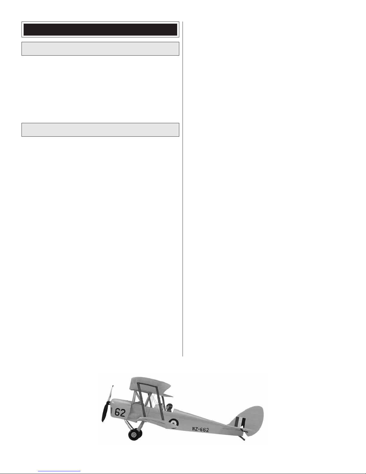
electrifly Tiger Moth User manual

Wingspan: 30 in [760mm]
Wing Area: 282 in2 [18.2 dm2]
Wing Loading: 4.1 oz/ft2 [13 g/dm2]
Length: 24.5 in [620mm]
Weight: 8.1 oz [230 g]
Radio: 3-channel, 2-micro servos
Motor: RimFire™250 (28-13-1750),
7.4V (2S) 300mAh LiPo,
SS-8 ESC
INSTRUCTION
MANUAL
Champaign, Illinois
(217) 398-8970, Ext 5
airsuppor[email protected]
Entire Contents © 2010 GPMA1134 Mnl
READ THROUGH THIS MANUAL BEFORE STARTING CONSTRUCTION. IT CONTAINS IMPORTANT
INSTRUCTIONS AND WARNINGS CONCERNING THE ASSEMBLY AND USE OF THIS MODEL.
WARRANTY
SPECIFICATIONS
Great Planes®Model Manufacturing Co. guarantees this kit to
be free from defects in both material and workmanship at the
date of purchase. This warranty does not cover any component
parts damaged by use or modification. In no case shall Great
Planes’ liability exceed the original cost of the purchased kit.
Further, Great Planes reserves the right to change or modify this
warranty without notice.
In that Great Planes has no control over the final assembly or
material used for final assembly, no liability shall be assumed nor
accepted for any damage resulting from the use by the user of
the final user-assembled product. By the act of using the
user-assembled product, the user accepts all resulting liability.
If the buyer is not prepared to accept the liability associated
with the use of this product, the buyer is advised to return
this kit immediately in new and unused condition to the
place of purchase.
To make a warranty claim send the defective part or item to
Hobby Services at the address below:
Hobby Services
3002 N. Apollo Dr. Suite 1
Champaign IL 61822 USA
Include a letter stating your name, return shipping address, as
much contact information as possible (daytime telephone
number, fax number, e-mail address), a detailed description of
the problem and a photocopy of the purchase receipt. Upon
receipt of the package the problem will be evaluated as quickly
as possible.

2
TABLE OF CONTENTS
INTRODUCTION . . . . . . . . . . . . . . . . . . . . . . . . . . . . . . . .2
AMA. . . . . . . . . . . . . . . . . . . . . . . . . . . . . . . . . . . . . . .2
SAFETY PRECAUTIONS . . . . . . . . . . . . . . . . . . . . . . . . .2
ADDITIONAL ITEMS REQUIRED . . . . . . . . . . . . . . . . . . .3
Motor, Battery, ESC Recommendations. . . . . . . . . . . .3
Radio Equipment . . . . . . . . . . . . . . . . . . . . . . . . . . . . .3
Adhesives and Building Supplies. . . . . . . . . . . . . . . . .3
KIT INSPECTION. . . . . . . . . . . . . . . . . . . . . . . . . . . . . . . .3
KIT CONTENTS. . . . . . . . . . . . . . . . . . . . . . . . . . . . . . . . .3
ASSEMBLY . . . . . . . . . . . . . . . . . . . . . . . . . . . . . . . . . . . .4
Mount the Wings . . . . . . . . . . . . . . . . . . . . . . . . . . . . .4
Mount the Stab and Fin . . . . . . . . . . . . . . . . . . . . . . . .6
Hook up the Elevator and Rudder . . . . . . . . . . . . . . . .6
Mount the Cowl and Landing Gear . . . . . . . . . . . . . . .8
Optional: Add the Flying Wires. . . . . . . . . . . . . . . . . .10
GETTHE MODEL READYTO FLY . . . . . . . . . . . . . . . . . 11
Check the ControlThrows . . . . . . . . . . . . . . . . . . . . . 11
Balance the Propeller. . . . . . . . . . . . . . . . . . . . . . . . . 11
Balance the Model (C.G.). . . . . . . . . . . . . . . . . . . . . .12
Charge the Batteries . . . . . . . . . . . . . . . . . . . . . . . . .13
MOTOR SAFETY PRECAUTIONS . . . . . . . . . . . . . . . . .13
FLYING. . . . . . . . . . . . . . . . . . . . . . . . . . . . . . . . . . . . . . .14
Ground Check and Range Check . . . . . . . . . . . . . . .14
Flight . . . . . . . . . . . . . . . . . . . . . . . . . . . . . . . . . . . . .14
INTRODUCTION
Thank you for purchasing the ElectriFly Tiger Moth Slow
Flyer EP ARF.The Tiger Moth was intended for indoor flying,
but is also fun to fly outdoors on evenings or in the morning
when the winds are still calm.
For the latest technical updates or manual corrections to the
Tiger Moth visit the ElectriFly web site at www.ElectriFly.com.
Open the “Airplanes” link, then select the ElectriFly Tiger
Moth ARF. If there is new technical information or changes
to this model a “tech notice” box will appear in the upper left
corner of the page.
Academy of Model Aeronautics
If you are not already a member of the AMA, please join!
The AMA is the governing body of model aviation and
membership provides liability insurance coverage, protects
modelers’ rights and interests and is required to fly at most
R/C sites.
Academy of Model Aeronautics
5151 East Memorial Drive
Muncie, IN 47302-9252
Tele. (800) 435-9262
Fax (765) 741-0057
Or via the Internet at:
http://www.modelaircraft.org
IMPORTANT!!! Two of the most important things you can
do to preserve the radio controlled aircraft hobby are to
avoid flying near full-scale aircraft and avoid flying near or
over groups of people.
PROTECT YOUR MODEL, YOURSELF
& OTHERS… FOLLOW THESE
IMPORTANT SAFETY PRECAUTIONS
1.YourTigerMothshouldnotbeconsidereda toy,butrathera
sophisticated, working model that functions very much like
afull-sizeairplane.Becauseofitsperformancecapabilities,
the Tiger Moth, if not assembled and operated correctly,
could possibly cause injury to yourself or spectators and
damage to property.
2.You must assemble the model according to the
instructions. Do not alter or modify the model, as
doing so may result in an unsafe or unflyable model.
In a few cases the instructions may differ slightly from
the photos. In those instances the written instructions
should be considered as correct.
3.You must take time to build straight, true and strong.
4.Youmust use an R/Cradio system that isin good condition,
a correctly sized motor, and other components as
specified in this instruction manual. All components must
be correctly installed so that the model operates correctly
on the ground and in the air.You must check the operation
of the model and all components before every flight.
5. If you are not an experienced pilot or have not flown this
type of model before, we recommend that you get the
assistance of an experienced pilot in your R/C club for
your first flights. If you’re not a member of a club, your
local hobby shop has information about clubs in your area
whose membership includes experienced pilots.
6.While this kit has been flight tested to exceed normal use,
if the plane will be used for extremely high stress flying,
such as aggressive aerobatics, or if a motor larger than
one in the recommended range is used, the modeler is
responsible for taking steps to reinforce the high stress
points and/or substituting hardware more suitable for the
increased stress.
We, as the kit manufacturer, provide you with a top quality,
thoroughly tested kit and instructions, but ultimately the
quality and flyability of your finished model depends
on how you build it; therefore, we cannot in any way
guarantee the performance of your completed model,
and no representations are expressed or implied as to the
performance or safety of your completed model.
Remember: Take your time and follow the instructions to
end up with a well-built model that is straight and true.

3
ADDITIONAL ITEMS REQUIRED
This is a partial list of items required to finish the Tiger Moth
that are illustrated in the instruction manual. Order numbers
are provided in parentheses.
Motor, Battery, ESC Recommendations
❍Great Planes®RimFire 250 (28-13-1750) Outrunner
motor (GPMG4502)
❍Great Planes ElectriFly 2S (7.4V) 300mAh 20C
Competition BP LiPo battery (GPMP0700)
❍Great Planes ElectriFly SS-8 8 Amp Brushless ESC
(electronic speed control) (GPMM1800)
❍Great Planes 8 x 6 Power Flow Slo-Flyer electric
propeller (GPMQ6610, qty. 2)
Radio Equipment
❍Minimum 3-channel radio control system
❍Two ES40 Pico micro servos (GPMM1200)
❍Mini/micro receiver (Futaba®R6004FF – FUTL7624)
Adhesive & Building Supplies
Other than common hobby tools, this is the list of
Adhesives and Building Supplies that were used to finish
the Tiger Moth.
❍Thin foam-safe CA (HOTR1040)
❍Medium foam-safe CA (HOTR1050)
❍CA applicator tips (GPMR6033)
❍CA accelerator (GPMR6035)
❍Great Planes Pro Threadlocker (GPMR6060)
❍#60 to #55 (.040" to .052") [1.0mm to 1.3mm] drill bit
❍Spare Propeller Saver O-rings (GPMG1405)
❍Optional: J&Z R/C 56 (or household white glue)
❍Optional: 3/4" fiber-reinforced tape (for reinforcing
wings, see page 4)
KIT INSPECTION
Before starting to build, take an inventory of this kit to make
sure it is complete, and inspect the parts to make sure they
areofacceptablequality.Ifanypartsare missing or arenotof
acceptable quality, or if you need assistance with assembly,
contact Product Support.
Great Planes Ph: (217) 398-8970, ext. 5
Product Support Fax: (217) 398-7721
3002 N Apollo Drive, Suite 1
Champaign, IL 61822
E-mail: airsuppor[email protected]
KIT CONTENTS
1Fuselage
2Bottom Wing
3Top Wing
4Horizontal Stabilizer (Stab)
5Vertical Stabilizer (Fin)
6Pilots
7Cowl
8Main Landing Gear
9Outer Wing Struts
10 Cabanes
11 Hook and Loop Material
12 Landing Gear Struts
1
6
2
4
9
10
11
12
8
7
3
5

4
ASSEMBLY
Mount the Wings
❏ 1. If you will be flying your Tiger Moth aggressively by
flyingitoutdoorsinwindyconditionsorperformingaggressive
aerobatics, or if you will be using servos, batteries or a motor
largerthan thoserecommended,apply two6" [150mm]strips
of 3/4" [20mm] fiber-reinforced tape to the bottom of both
wings as shown. (We marked light centerlines on the strips
of tape to make them easier to center.) If you will be flying
your Tiger Moth in calm conditions or indoors in a normal,
scale-like manner, no reinforcement is required.
❏ 2. Use a sharp hobby knife to cut the skin from the top of
the bottom wing over the holes for the landing gear struts.
❏ 3. Also cut the skin from both sides of the bottom wing
over the notches for the outer wing struts.(There is no need
to cut the skin from the slots in the top wing.)
❏ 4. Cut the C.G. marking template from the back of the
manual.Tape the template to the top of the bottom wing with
the front edges of the template aligned with the leading edge.
Use a small pin or a sharpened pencil to lightly puncture
small dimples through the cross marks in the template
into the wing skin. When balancing the plane later, it will
be suspended with sharpened pencils or pens “keyed” into
the dimples. Note: Should you ever need to re check the
balance in the future but have misplaced your template, the
recommended balance point is 15/16" [23.8mm] from the
leading edge of the bottom wing at the fuselage sides.The
forward balance point is 3/4" [19.1mm] and the aft balance
point is 1-1/8" [28.6mm].

5
❏ 5.Test fit the bottom wing to the fuselage just to see how
it fits.Remove the wing and apply a bead of thick or medium
foam-safe CA to the wing saddle and fit the wing back into
position. Glue the front and back of the wing to the fuselage
as well.
❏ 6.Test fit the cabanes as shown, making certain they
are all the way down into the “pockets” in the fuselage.View
the top edges of the cabanes to make sure they align with
each other.Make any adjustments necessary.Then, glue the
cabanes into position with foam-safe CA.
Top Wing
❏ 7.Test fit the top wing to the cabanes. View the model
from the bottom, making sure the leading edge of the top
wing is parallel with the leading edge of the bottom wing. If
necessary, there should be enough free play in the notches
torotate the top wingto get italigned.If you need to move the
top wing but cannot, the notches may be slightly enlarged.
❏ 8. Once you can get the top wing aligned with the bottom
wing, glue it to the cabanes with a small amount of thin,
foam-safe CA—using only a little thin CA will allow it to
harden faster and keep excess from running all over the rest
of the wing or dripping onto your clothes or workbench!
Refer to this photo for the following two steps.
❏ 9.Test fit the outer struts to the top and bottom wings.
Then, glue the struts to the bottom wings only with a small
amount of thin CA.
❏ 10.As when gluing the top wing to the cabanes, view
the model from the bottom. Note the alignment between
the leading edge of the top and bottom wing to see if they
are parallel with each other. If necessary, adjust the top
wing on the struts until the leading edges are parallel.Then,
glue the top wing to the struts with a small amount of thin,
foam-safe CA.

6
❏ 11. After the CA on the struts and cabanes has hardened,
follow with fillets of J&Z R/C 56 or thick or medium foam-safe
CA to all the glue joints of the wings including the bottom
wing to the fuselage and both wings to the cabanes and
outer struts.
Mount the Stab and Fin
❏ 1. Use a sharp hobby knife to cut the skin from all the
slots and notches in the horizontal stabilizer (stab), elevator
and rudder.
❏ 2. Make sure the elevator and rudder can move up and
down and left and right freely by flexing them back and forth a
few times. If the hinge joints seem too rigid, move them back
and forth a few more times to about a 45-degree angle in both
directions.When you do the elevator, align the hinge line with
the edge of your workbench or a cardboard box to keep the
elevator halves aligned.
❏ 3. Glue the fin to the stab, making sure the two are
perpendicular.NOTE: Becertainthat the slotfortheelevator
horn is on the right side.
❏ 4. Hold the stab to the fuselage and view the model from
the rear to see if it is parallel with the bottom wing.If the stab
is not parallel with the bottom wing, lightly sand or trim the
high side of the stab saddle to get the stab to align.
❏ 5.The same way you glued on the wing, apply thick or
medium foam-safe CA to the stab saddle and then set the
stab down into position. Make sure the leading edge of the
fin is centered over the top of the fuselage.Hold the stab in
position long enough for the glue to set (or use a light mist
of CA accelerator).
Hook Up the Elevator & Rudder
❏ 1. Connect both pushrods to the control horns with the
micro FasLink™connectors as shown.

7
❏ 2. Guide the rudder pushrod up through the rudder tube
in the left side of the fuselage.Then, fit and glue the rudder
horn into the elevator.
❏ 3. Fit and glue the elevator horn into the elevator the
same way.
Cut
Make two
❏ 4. Make two single-arm servo arms by cutting off the
unused arms.
ELEVATOR RUDDER
ES40 Pico servos
Middle
hole
Inner
hole
ELEVATOR RUDDER
“Other”
servo arms
5/16" [7.5mm] 13/32" [10mm]
❏ 5. If using ES-40 Pico servos, mount a screw-lock
connector to the middle hole of one servo arm and to the
inner hole of the other servo arm. If using different servos,
mount the connectors in the holes closest to 5/16" [7.5mm]
and 13/32" [10mm] from center.
❏ 6.Turnonyourtransmitterandcenterthetrims.Temporarily
connect the servos to your receiver. Connect the ESC to the
receiver and a battery to the ESC so you can power up the
system. Mount the servo arms to the servos.
❏ 7. Unplug the servos and the ESC from the receiver and
mount the servos to the servo tray in the fuselage with the
screws that came with this kit (or with the screws that came
with the servos).

8
Refer to these photos for mounting
the receiver, ESC and motor.
❏ 8. Reconnect the servos and the ESC to the receiver.Use
the included adhesive-backVelcro or double-sided adhesive
foam tape (not included) to mount the receiver wherever
convenient, such as to the sides or top of the “engine box”
or to the back of the former in the servo compartment
where shown.If you do mount the receiver back in the servo
compartment, make sure the pushrods and servo arms don’t
hit the receiver when the servo arms rotate forward.
❏ 9. Mount the ESC where shown. Apply a strip of the
rougher,“hook side”of adhesive-backedVelcro where shown
for the battery.
❏ 10. Mount the motor to the firewall with the three included
2mm x 8mm Phillips wood screws.Connect the motor wires
to the ESC and make sure the motor is turning the correct
direction by plugging in the battery and running the motor.
If the motor is turning the wrong direction, switch any two
motor/ESC wires with each other.
❏ 11.With the radio on and the trims centered, center the
rudder and elevator and tighten down the screws in the
screw-lock connectors to lock the pushrods down. Use the
control sticks on your transmitter to move the elevator and
rudder, making sure they respond in the correct direction.
If necessary, use the servo reversing function in your
transmitter to reverse the servos so the elevator, rudder and
throttle respond correctly.
Mount the Cowl & Landing Gear
❏ 1.Use medium-grit sandpaper to roughen the inner
surfaces of the forward legs on the plywood landing
gear struts where they will be glued to the main landing
gear wires.
❏ 2. Use a small piece of paper towel or a small cloth
dampened with denatured alcohol or other solvent to wipe
any residual oils or contaminants from the landing gear
wires. Use medium-grit sandpaper to scuff the gear wire so
glue will adhere.
Refer to this photo for the next two steps.
❏ 3. Insert the main landing gear wire into the fuselage—
the gear should fit tightly enough to stay in on its own, but if
it doesn’t fit tightly add a drop of thin, foam-safe CA to the
legs where they go into the mounts.
❏ 4. One at a time, position the struts to the gear and in
the wing and glue them to the gear wires with thin CA. Hint:
before positioning the struts,“prime”them with a light mist of
CA accelerator sprayed from a distance of approximately 12"
[300mm].This will cause the CA to harden faster, preventing
it from running down onto the rest of the model.

9
❏ 5. Once the struts have been glued to the gear wires,
apply a small fillet of thick or medium CA to the wire and the
struts securely holding them on.
❏ 6. Carefully cut a small bevel the bottom corners of the
front fuselage former.
❏ 7. Measure and note the distance from the front edge of
the cabanes to the center of the cowl mounting block. (It
should be approximately 7/8" [22mm].)
❏ 8. Make sure you have a small drill bit from .040" to .052"
(#60 to #55) [1.0mm to 1.3mm] for drilling the cowl mounting
screw holes. Don’t be tempted to use a 1/16" [1.6mm] drill
found in common drill assortments because it is too large.
❏ 9. Fit the cowl over the fuselage so the cutout for the
propeller adapter will clear the adapter and the prop-saver
O-ring screws. Also turn the motor to make sure it is not
rubbing the inside of the cowl.Using the measurement taken
in the previous step, hold the cowl in position and drill a hole
through the top of the cowl into the cowl block.
❏ 10. Secure the top of the cowl to the fuselage block with
a 1.6mm x 4mm Phillips wood screw.
❏ 11.Turn the fuselage over. Holding the cowl in position,
drill another hole through the bottom corner into the center
of the plywood laminations that comprise the front former
and the landing gear mount.

10
❏ 12. Secure the cowl with another 1.6mm x 4mm Phillips
wood screw. Drill the third and final hole opposite the one
drilled in the previous step and insert another screw.
❏ 13.While you’re adding finishing touches, glue in one or
both pilots.
Optional: Add the Flying Wires
The flying wires are not required, but they add that one final
piece of scale detail for even more realism. If you do install
the flying wires, they should be tight enough to remain taut,
but not so tight as to introduce any twist into the wings. To
make the flying wires you’ll need some black heavy/medium
thread and a toothpick.
❏ 1. Use a pin to puncture the molded-in dimples in the
bottom wing up through the top skin.
❏ 2. Cut an approximately 30" [760mm] length of black
thread.Insert both ends of the thread down through the hole
you punctured in one of the wings.
❏ 3. Cut two 1/4" [6mm] pieces from a toothpick. Loop the
string around one of the toothpick pieces on the bottom
of the wing and pull the string through until it stops. Add
a few drops of foam-safe CA to the string and toothpick to
permanently glue it in.
❏ 4. Loop one end of the string around one of the holes in
the top of the outer strut. Lightly pull the line to apply some
tension. Then, add a drop of thin CA where it loops around
the strut and allow to harden. Tie off the other end of the
flying wire to the other hole in the top of the strut the same
way. Cut off excess thread.
❏ 5. Add the bottom flying wires to the other side of the
bottom wing the same way—be certain not to pull the strings
too tight or you may introduce twist into the wings.
❏ 6. Add the top flying wires that go from the top of the
cabanes down to the bottom of the struts—the easiest way
is to first tie one end of the thread around one of the holes in
the bottom of the outer strut, loop it through the hole in the
top of the cabane, then tie the other end down to the other
hole in the bottom of the outer strut. Note that the front wire
that runs from the bottom of the struts up to the cabane runs
between the other wires coming from the bottom of the wing
next to the fuselage.

11
GET THE MODEL READY TO FLY
Check the Control Throws
Ifthepushrodswereconnected tothe servoarmsusingthe
measurements provided in this manual, then the control
throws should already be correct, or very nearly correct.
However, it’s still a good idea to check the throws since
they have such a great effect on how the model flies.
❏ 1.Prop up the rear of the fuselage on a box or
something similar so the horizontal stabilizer will be level
or very nearly level.Turn on your transmitter and connect
a battery to the ESC.
❏ 2. Place a ruler next to the trailing edge of the elevator at
the widest part. Note the measurement.
❏ 3.Use the transmitter to move the elevator to full “up”
and note how far the elevator moved. This is the “up”
elevator throw.
❏ 4. Make sure the up elevator throw you measured is
the same as the throw specified below. Measure the down
elevator throw and the right and left rudder throw the same
way. If necessary, use the ATVs in your transmitter to adjust
the throws. If your radio does not have ATVs and if your
throws are not close to the specifications provided, you can
change the throws by relocating the pushrods on the servo
arms. Moving the pushrods inward will provide less throw
and moving the pushrods out will increase the throw.
These are the recommended control surface throws:
ELEVATOR
HIGH RATE LOW RATE
5/8"
[16mm]
17deg
Up
5/8"
[16mm]
17deg
Down
3/8"
[10mm]
10 deg
Up
3/8"
[10mm]
10 deg
Down
RUDDER 1-1/4"
[32mm]
27 deg
Right
1-1/4"
[32mm]
27 deg
Left
3/4"
[19mm]
16 deg
Right
3/4"
[19mm]
16 deg
Left
Balance the Propeller
Take a few minutes to balance your propeller and a spare
propeller before you fly. A balanced propeller will help the
motor run smoothly and efficiently.
If the propeller is unbalanced, use a single-edge razor blade
or a hobby knife to scrape material off the heavy blade until
you can get the propeller to balance.

12
Balance the Model (C.G.)
More than any other factor, the C.G. (center of gravity/
balance point) can have the greatest effect on how a
model flies. If you value your model and wish to enjoy it
for many flights, DO NOT OVERLOOKTHIS IMPORTANT
PROCEDURE. A model that is not properly balanced may
be unstable and possibly unflyable.
❏ 1. Mount the propeller (not included) to the propeller
adapterwiththeprop-saverO-ringthatcamewiththeRimFire
motor. A Great Planes 8 x 6 ElectriFly PowerFlow™Slow-
Flyer propeller (GPMQ6610) is recommended. The easiest
way to mount the prop is first to hook the O-ring around one
of the screws, fit the propeller, and then use a small (#00)
Phillips screwdriver to loop the O-ring around the propeller
hub and the other screw.Suggestion: Purchase spare Prop
Saver O-Rings (GPMG1405).
❏ 2. Optional: Fit the servo cover over the servo
compartment. If necessary, use a couple of small strips of
tape to hold the cover in place.
❏ 3. Ifyouhaven’tdonesoalready, attachastripofthesofter,
“loop” side of the included Velcro hook-and-loop material to
the motor battery. Install the motor battery in the fuselage to
the other Velcro strip you attached earlier.
At this stage the model should be in ready-to-fly condition
with all of the systems in place including the motor, complete
radio system, ESC, propeller and battery.
❏ 4. Place the model upside-down. Use two pencils or
ballpoint pens to lift the model at the middle dimples you
marked earlier with the template, noting the recommended
balance point.

13
This is where your Tiger Moth should balance for the first
flights.Later,youmayexperiment byshifting theC.G.3/16"
[4.8mm] forward or 3/16" [4.8mm] back to change the
flying characteristics.Moving the C.G.forward will improve
the smoothness and stability and allow your Tiger Moth to
perform tighter turns, but the model will fly slightly faster.
Moving the C.G. aft allows the model to fly more slowly,
but will require slightly more pilot control in tightly-banked
turns. In any case, start at the recommended balance
point and do not at any time balance the model outside
the specified range.
If the model is balanced properly it should rest level when
viewed from the side. If the tail is down the model is “tail-
heavy” and nose weight will be required. If the nose drops
the model is “nose-heavy” and tail weight will be required. If
you are using the components recommended in this manual
it is likely that the model will balance at the recommended
C.G.location, or possibly require 1/4 to 3/8 oz.[7g to 11g] of
nose weight.
❏ 5. If any weight is required to get the model to balance,
first determine how much by placing segments of Great
Planes “stick-on”lead (GPMQ4485) over the location on the
fuselage where it will be attached inside and rechecking the
balance.A good place to attach tail weight is to the inside of
one of the fuselage sides under the horizontal stab. A good
place to attach nose weight is to the top of the “motor box”
right behind the firewall. Do not attach nose weight to the
cowl because it will cause stress around the mounting screw
holes.
❏ 6. Once you know how much weight is required, attach it
in the fuselage.Then, recheck the balance.
Charge the Batteries
Follow the battery charging instructions that came with
your radio control system to charge the transmitter
batteries. You should always charge your transmitter the
night before flying, and at other times as recommended by
the radio manufacturer.
CAUTION: Unless the instructions that came with your
radio system state differently, the initial charge on new
transmitter and receiver batteries should be done for 15
hours using the slow-charger that came with the radio
system.This will “condition” the batteries so that the next
charge may be done using the fast-charger of your choice.
If the initial charge is done with a fast-charger the batteries
may not reach their full capacity and you may be flying with
batteries that are only partially charged.
MOTOR SAFETY PRECAUTIONS
Failure to follow these safety precautions may result in
severe injury to yourself and others.
● Use safety glasses when starting or running motors.
● Do not run the motor in an area of loose gravel or
sand; the propeller may throw such material in your
face or eyes.
● Keep your face and body as well as all spectators
away from the plane of rotation of the propeller as
you start and run the motor.
● Keep loose clothing, shirt sleeves, ties, scarfs, long
hair or loose objects such as pencils or screwdrivers
that may fall out of shirt or jacket pockets away from
the prop.
14
FLYING
Ground Check & Range Check
When you get to your flying site follow the manufacturer’s
instructions that came with your radio to ground check the
operationalrangeofyourradio.Thisshouldbedonebothwith
the motor off and with the motor running at various speeds.
If the motor or control surfaces do not respond correctly or
move erratically without command, do not fly! Find and
correct the problem first.Look for loose servo connections or
broken or loose motor or battery wires.
Flight
Taking off from the ground is desirable if you are flying
indoors or outdoors where there is a smooth runway surface.
However, if no smooth surface is available the Tiger Moth
may easily be hand-launched.
No matter where you fly, the first thing you should do is
check the controls after turning on the transmitter and
connecting the battery. Make sure the controls respond and
in the correct direction.
To take off from the ground, simply set the model down facing
into any prevailing breeze. Smoothly advance the throttle all
the way. Initially, the rudder will have little effect, but after a
second or two when there is sufficient airflow the rudder will
become effective. Use the rudder to steer the model.
When theTiger Moth has gained sufficient flying speed apply
“up” elevator, establishing a gentle (20 – 30-degree) climb.
If hand-launching your Tiger Moth, double-check to make
sure that the controls are working correctly. Then, apply full
throttle.Facing into any prevailing wind, gently toss theTiger
Moth into the air. Apply “up” elevator to establish a climb.
Once well clear of the ground make the first turn away from
yourself. Use the trims to get the model to fly straight-and-
level at your preferred flying speed—in smaller arenas/
gymnasiums you will probably be most comfortable flying
your Tiger Moth at about 1/4 – 1/3 throttle. In larger arenas
or outdoors you will probably fly your Tiger Moth at 1/2 or
higher throttle settings.
Execute turns to see how the Tiger Moth reacts. The Tiger
Moth should be able to execute tightly-banked turns with a
diameter of approximately 15’–20’ [4.5m – 6m] (although
this is not so important if you are flying in a large arena or
outdoors). If, during the tightest turns the Tiger Moth noses
up and seems to get “stuck” in the turn, nose weight may be
required. If you don’t feel the Tiger Moth flies slowly enough
or if it doesn’t react quickly enough to your control inputs, tail
weight (or removing a portion of any nose weight) may help.
While the Tiger Moth is still high in the air and you have
plenty of battery power, another good exercise is to cut the
throttle and observe how theTiger Moth glides.This will give
you an indication of what it will do when it’s time to land.
When ready to land, simply cut motor power and make
the final turn to your landing area. Allow the Tiger Moth to
establish a slightly nose-down attitude to maintain airspeed.
If necessary, modulate the throttle and elevator to control
the glide path. As you get closer to the ground continue to
apply “up” elevator, causing the Tiger Moth to fly slower and
slower until it finally touches down the precise moment it can
no longer fly.
One final note about flying your model. Have a goal or flight
plan in mind for every flight. This can be learning a new
maneuver(s), improving a maneuver(s) you already know,
or learning how the model behaves in certain conditions
(such as on high or low rates). This is not necessarily to
improve your skills (though it is never a bad idea!), but more
importantly so you do not surprise yourself by impulsively
attempting a maneuver and suddenly finding that you’ve run
out of time, altitude or airspeed. Every maneuver should be
deliberate, not impulsive.For example, if you’re going to do a
loop,checkyouraltitude,mindthewinddirection(anticipating
rudder corrections that will be required to maintain heading),
remember to throttle back at the top, and make certain you
are on the desired rates (high/low rates).A flight plan greatly
reduces the chances of crashing your model just because of
poor planning and impulsive moves.Remember to think.
Have a ball! But always stay in control
and fly in a safe manner.
GOOD LUCK AND GREAT FLYING!

Spare C.G. MarkingTemplate
Fuselage Sides
1-1/8" [28.6mm]
15/16" [23.8mm]
3/4" [19.1mm]
C.G. MarkingTemplate
Fuselage Sides
1-1/8" [28.6mm]
15/16" [23.8mm]
3/4" [19.1mm]
This model belongs to:
Name
Address
City, State, Zip
Phone Number
AMA Number
15

Table of contents
Other electrifly Toy manuals

electrifly
electrifly SR22Turbo User manual

electrifly
electrifly PBY CATALINA User manual

electrifly
electrifly reflection User manual

electrifly
electrifly Super Sportster RX-R User manual

electrifly
electrifly ElectriFly User manual

electrifly
electrifly Spad XIII User manual

electrifly
electrifly L-39 User manual
Popular Toy manuals by other brands

Heli-Professional
Heli-Professional SOXOS 550 KIT Assembly instruction and manual

REVELL
REVELL Control SPEEDBOAT MAXI user manual

Vmar
Vmar Nouvo 1300 EP instruction manual

Kadee
Kadee 708 Assembly & instruction manual

Centuri
Centuri 33 Technical information report

LEGO
LEGO STAR WARS 10221 Building instructions


