electrifly Super Sportster RX-R User manual

®
INSTRUCTION
MANUAL
Champaign, Illinois
(217) 398-8970, Ext 5
airsuppor[email protected]
Entire Contents © 2011 Hobbico,
®Inc. All rights reserved. GPMA6006 Mnl
READ THROUGH THIS MANUAL BEFORE STARTING CONSTRUCTION. IT CONTAINS IMPORTANT
INSTRUCTIONS AND WARNINGS CONCERNING THE ASSEMBLY AND USE OF THIS MODEL.
WARRANTY
SPECIFICATIONS
Great Planes®Model Manufacturing Co. guarantees this kit to
be free from defects in both material and workmanship at the
date of purchase. This warranty does not cover any component
parts damaged by use or modification. In no case shall Great
Planes’ liability exceed the original cost of the purchased kit.
Further, Great Planes reserves the right to change or modify this
warranty without notice.
In that Great Planes has no control over the final assembly or
material used for final assembly, no liability shall be assumed nor
accepted for any damage resulting from the use by the user of
the final user-assembled product. By the act of using the
user-assembled product, the user accepts all resulting liability.
If the buyer is not prepared to accept the liability associated
with the use of this product, the buyer is advised to return
this kit immediately in new and unused condition to the
place of purchase.
To make a warranty claim send the defective part or item to
Hobby Services at the address below:
Hobby Services
3002 N. Apollo Dr. Suite 1
Champaign IL 61822 USA
Include a letter stating your name, return shipping address, as
much contact information as possible (daytime telephone
number, fax number, e-mail address), a detailed description of
the problem and a photocopy of the purchase receipt. Upon
receipt of the package the problem will be evaluated as quickly
as possible.
Wingspan: 40 in [1015mm]
Wing Area: 267 in2 [17.2 dm2]
Wing Loading: 10.8−11.5 oz/ft2
[33−35 g/dm2]
Length: 32.5 in [825mm]
Weight: 20−22 oz [565−605 g]
Radio: 4-channel minimum
™
™
2
INTRODUCTION
Congratulations on your purchase of the Great Planes Super
Sportster Rx-R EPO! Continuing with the success of the Super
Sportster design since its introduction in 1982 comes the EPO
version.You can expect the same honest flight characteristics
with the EPO Sportster as the larger wood counterparts. If
this is your first Super Sportster, then you will discover and
appreciate the sporty handling of the plane. If this is your first
low wing model, the Sportster can be flown slow and gentle
as you become accustomed to flying a plane without the self-
righting tendency your high wing trainer has.
The practical wingspan allows you to toss the Sportster into
the back seat of any size car without having to take the wings
off. Grab a flight or two over your lunch at a spacious park or
your local field! And the EPO material is very resilient against
rough landings, but should damage occur, it can be repaired
quickly using regular CA glue and accelerator so you can
keep on flying.
For the latest technical updates or manual corrections to the
Super Sportster EPO visit the Great Planes web site at www.
greatplanes.com. Open the “Airplanes” link, then select the
Super Sportster EPO. If there is new technical information or
changes to this model a “tech notice” box will appear in the
upper left corner of the page.
AMA
We urge you to join the AMA (Academy of Model Aeronautics)
and a local R/C club.The AMA is the governing body of model
aviation and membership is required to fly at AMA clubs.
Though joining the AMA provides many benefits, one of the
primary reasons to join is liability protection. Coverage is not
limited to flying at contests or on the club field. It even applies
to flying at public demonstrations and air shows. Failure to
comply with the Safety Code (excerpts printed in the back of
the manual) may endanger insurance coverage. Additionally,
training programs and instructors are available at AMA club
sites to help you get started the right way.There are over 2,500
AMA chartered clubs across the country. Contact the AMA at
the address or toll-free phone number below:
Academy of Model Aeronautics
5151 East Memorial Drive
Muncie, IN 47302-9252
Tele. (800) 435-9262
Fax (765) 741-0057
Or via the Internet at: http://www.modelaircraft.org
IMPORTANT!!! Two of the most important things you can
do to preserve the radio controlled aircraft hobby are to avoid
flying near full-scale aircraft and avoid flying near or over
groups of people.
SAFETY PRECAUTIONS
ProtectYour Model,Yourself & Others...
FollowThese Important Safety Precautions
1. Your Super Sportster EPO should not be considered
a toy, but rather a sophisticated, working model that
functions very much like a full-size airplane. Because of
its performance capabilities, the Sportster, if not assembled
and operated correctly, could possibly cause injury to
yourself or spectators and damage to property.
2. You must assemble the model accordingto theinstructions.
Do not alter or modify the model, as doing so may result in
an unsafe or unflyable model. In a few cases the instructions
may differ slightly from the photos. In those instances the
written instructions should be considered as correct.
3. You must take time to build straight, true and strong.
TABLE OF CONTENTS
INTRODUCTION . . . . . . . . . . . . . . . . . . . . . . . . . . . . . . . . 2
AMA . . . . . . . . . . . . . . . . . . . . . . . . . . . . . . . . . . . . . . . 2
SAFETY PRECAUTIONS . . . . . . . . . . . . . . . . . . . . . . . . . 2
DECISIONSYOU MUST MAKE. . . . . . . . . . . . . . . . . . . . . 3
Radio Equipment . . . . . . . . . . . . . . . . . . . . . . . . . . . . . 3
Batteries and Charger . . . . . . . . . . . . . . . . . . . . . . . . . 3
Optional Supplies and Tools. . . . . . . . . . . . . . . . . . . . . 3
IMPORTANT BUILDING NOTES. . . . . . . . . . . . . . . . . . . . 4
KIT INSPECTION. . . . . . . . . . . . . . . . . . . . . . . . . . . . . . . . 4
ORDERING REPLACEMENT PARTS. . . . . . . . . . . . . . . . 4
KIT CONTENTS. . . . . . . . . . . . . . . . . . . . . . . . . . . . . . . . . 4
BUILDING INSTRUCTIONS . . . . . . . . . . . . . . . . . . . . . . . 5
GETTHE MODEL READYTO FLY . . . . . . . . . . . . . . . . . . 7
Check the Control Directions . . . . . . . . . . . . . . . . . . . . 7
Set the Control Throws. . . . . . . . . . . . . . . . . . . . . . . . . 8
Balance the Model (C.G.). . . . . . . . . . . . . . . . . . . . . . . 8
Balance the Model Laterally. . . . . . . . . . . . . . . . . . . . . 9
PREFLIGHT. . . . . . . . . . . . . . . . . . . . . . . . . . . . . . . . . . . . 9
Identify Your Model. . . . . . . . . . . . . . . . . . . . . . . . . . . . 9
Charge the Batteries . . . . . . . . . . . . . . . . . . . . . . . . . . 9
Balance Propellers. . . . . . . . . . . . . . . . . . . . . . . . . . . . 9
Range Check . . . . . . . . . . . . . . . . . . . . . . . . . . . . . . . . 9
MOTOR SAFETY PRECAUTIONS . . . . . . . . . . . . . . . . . 10
AMA SAFETY CODE. . . . . . . . . . . . . . . . . . . . . . . . . . . . 10
General . . . . . . . . . . . . . . . . . . . . . . . . . . . . . . . . . . . 10
Radio Control . . . . . . . . . . . . . . . . . . . . . . . . . . . . . . . 10
CHECK LIST . . . . . . . . . . . . . . . . . . . . . . . . . . . . . . . . . . 11
FLYING. . . . . . . . . . . . . . . . . . . . . . . . . . . . . . . . . . . . . . . 11
Takeoff . . . . . . . . . . . . . . . . . . . . . . . . . . . . . . . . . . . . 11
Flight . . . . . . . . . . . . . . . . . . . . . . . . . . . . . . . . . . . . . 11
Landing . . . . . . . . . . . . . . . . . . . . . . . . . . . . . . . . . . . 12

3
4. You must use an R/C radio system that is in first-class
condition, and a correctly sized motor and components
throughout the building process.
5. You must correctly install all R/C and other components
so that the model operates correctly on the ground and in
the air.
6. You must check the operation of the model before every
flight to insure that all equipment is operating and that the
model has remained structurally sound. Be sure to check
clevises or other connectors often and replace them if they
show any signs of wear or fatigue.
7. If you are not an experienced pilot or have not flown this
type of model before, we recommend that you get the
assistance of an experienced pilot in your R/C club for
your first flights. If you’re not a member of a club, your
local hobby shop has information about clubs in your area
whose membership includes experienced pilots.
8. While this kit has been flight tested to exceed normal use, if
the plane will be used for extremely high stress flying, such
as racing, or if a motor larger than one in the recommended
range is used, the modeler is responsible for taking steps to
reinforce the high stress points and/or substituting hardware
more suitable for the increased stress.
We, as the kit manufacturer, provide you with a top quality,
thoroughly tested kit and instructions, but ultimately the
quality and flyability of your finished model depends
on how you build it; therefore, we cannot in any way
guarantee the performance of your completed model,
and no representations are expressed or implied as to the
performance or safety of your completed model.
Remember:Take your time and follow the instructions to
end up with a well-built model that is straight and true.
DECISIONS YOU MUST MAKE
This is a partial list of items required to finish the Super Sportster
EPO that may require planning or decision making before
starting to build. Order numbers are provided in parentheses.
Radio Equipment
The Super Sportster EPO requires a minimum 4-channel
transmitter and receiver. If you have a transmitter already, a
standard 2.4GHz receiver or micro FM receiver is recommended.
If you need to purchase a transmitter, we recommend the
Futaba 6EX 2.4GHz transmitter/receiver combo as it provides
digital trims, dual rates and end point adjustments, model
memory and other mixing options that will be useful for future
model airplanes or helicopters you purchase. Part numbers
for these models are provided below:
❍Futaba®6EX 6-Channel 2.4GHz Transmitter/Receiver
(FUTK6900)
❍Futaba R617FS 7-Channel 2.4GHz FASST
™
Receiver
(FUTL7627)
Batteries and Charger
One 1250-1300mAh 11.1V Lithium Polymer battery pack is
required. Recommended batteries are provided below.
❍SuperTigre®LiPo 11.1V 1250mAh 15C (SUPP1030)
❍Great Planes ElectriFly LiPo 3S 11.1V 1300mAh 25C
Power (GPMP0505)
The Great Planes 1300mAh pack will require the use
of an adapter (SUPM0040)
A cell balancer is required for the LiPo battery packs
listed above:
❍Great Planes ElectriFly Equinox™ LiPo Cell Balancer
1-5 (GPMM3160)
A suitable charger is also required. The Great Planes
PolyCharge4 is designed for LiPo packs only, but is able to
charge four LiPo packs simultaneously. The Great Planes
Triton2 charger will only charge one pack at a time. However, it
is capable of charging NiCd, NiMH, LiPo, and Pb acid batteries.
Order numbers for both are provided below:
❍Great Planes PolyCharge4™ DC Only 4 Output LiPo
Charger (GPMM3015)
OR
❍Great Planes ElectriFly Triton2™ DC Comp Peak Charger
(GPMM3153)
Optional Supplies and Tools
Here is a list of optional tools and adhesives that will help you
set up and repair the Super Sportster EPO:
❍1/2 oz. [15g] Medium Pro™ CA+ (GPMR6007)
❍2 oz. [57g] spray CA activator (GPMR6035)
❍4 oz. [113g] aerosol CA activator (GPMR6034)
❍CA applicator tips (HCAR3780)
❍CA debonder (GPMR6039)
❍Pro 6-minute epoxy (GPMR6045)
❍Pro 30-minute epoxy (GPMR6047)
❍Epoxy brushes 6, (GPMR8060)
❍Mixing sticks (GPMR8055)
❍Mixing cups (GPMR8056)
❍Precision Magnetic Prop Balancer (TOPQ5700)
❍AccuThrow™ Deflection Gauge (GPMR2405)
❍CG Machine™ (GPMR2400)
❍Hobbico Flexible 18" Ruler Stainless Steel (HCAR0460)
❍Denatured alcohol (for epoxy clean up)

4
IMPORTANT BUILDING NOTES
●Photos and sketches are placed before the step they refer
to. Frequently you can study photos in following steps to
get another view of the same parts.
●The stabilizer and wing incidences and motor thrust angles
have been factory-built into this model. However, some
technically-minded modelers may wish to check these
measurements anyway.To view this information visit the web
site at www.greatplanes.com and click on “Technical Data.”
Due to manufacturing tolerances which will have little or no
effect on the way your model will fly, please expect slight
deviations between your model and the published values.
KIT INSPECTION
Before starting to build, take an inventory of this kit to make
sure it is complete, and inspect the parts to make sure they
are of acceptable quality. If any parts are missing or are not
of acceptable quality, or if you need assistance with assembly,
contact Product Support.When reporting defective or missing
parts, use the part names exactly as they are written in the
Kit Contents list.
Great Planes Product Support
3002 N Apollo Drive, Suite 1 Ph (217) 398-8970, ext. 5
Champaign, IL 61822 Fx (217) 398-7721
E-mail: [email protected]
ORDERING REPLACEMENT PARTS
Replacement parts for the Great Planes Super Sportster EPO
are available using the order numbers in the Replacement
Parts List that follows.The fastest, most economical service
can be provided by your hobby dealer or mail-order company.
To locate a hobby dealer, visit the Hobbico web site at www.
hobbico.com. Choose “Where to Buy” at the bottom of the menu
on the left side of the page. Follow the instructions provided
on the page to locate a U.S., Canadian or International dealer.
Parts may also be ordered directly from Hobby Services by
calling (217) 398-0007, or via facsimile at (217) 398-7721, but
full retail prices and shipping and handling charges will apply.
Illinois and Nevada residents will also be charged sales tax. If
ordering via fax, include a Visa®or MasterCard®number and
expiration date for payment.
Mail parts orders Hobby Services
and payments by 3002 N Apollo Drive, Suite 1
personal check to: Champaign IL 61822
Be certain to specify the order number exactly as listed in the
Replacement Parts List. Payment by credit card or personal
check only; no C.O.D.
If additional assistance is required for any reason contact
Product Support by e-mail at productsupport@greatplanes.
com, or by telephone at (217) 398-8970.
Order No. Description
REPLACEMENT PARTS LIST
GPMA4215
GPMA4216
GPMA4217
GPMA4218
GPMA4219
GPMA4220
GPMA4221
GPMA4222
GPMA4223
GPMA4224
GPMA4225
GPMA4226
GPMA4227
Super Sportster EP Rx-R Wing
Super Sportster Rx-R Fuselage
Super Sportster Rx-R H-Stab
Super Sportster EP Rx-R Cowl
Super Sportster EP Rx-R Gear
Super Sportster EP Rx-R Spinner
Super Sportster EP Rx-R Hatch
Super Sportster EP Rx-R Motor
Super Sportster EP Rx-R ESC
Super Sportster EP Rx-R Servo
Super Sportster Rx-R T-Wheel
Super Sportster Rx-R Wing Tube
Wing Bolt 1 pc.
1. Fuselage
2. Canopy Hatch
3. Left and Right Wing Panels
4. Wing Tube
5. Left and Right Horizontal Stabilizers
6. Propeller
7. Spinner
8. Left and Right Main Landing Gear
1
6
2
4
8
7
3
5
3
5
8
KIT CONTENTS
5
BUILDING INSTRUCTIONS
❏1. If you have not done so already, remove the major
parts of the kit from the box and inspect for damage. If any
parts are damaged or missing, contact Product Support at
the address or telephone number listed in the “Kit Inspection”
section on page 4.
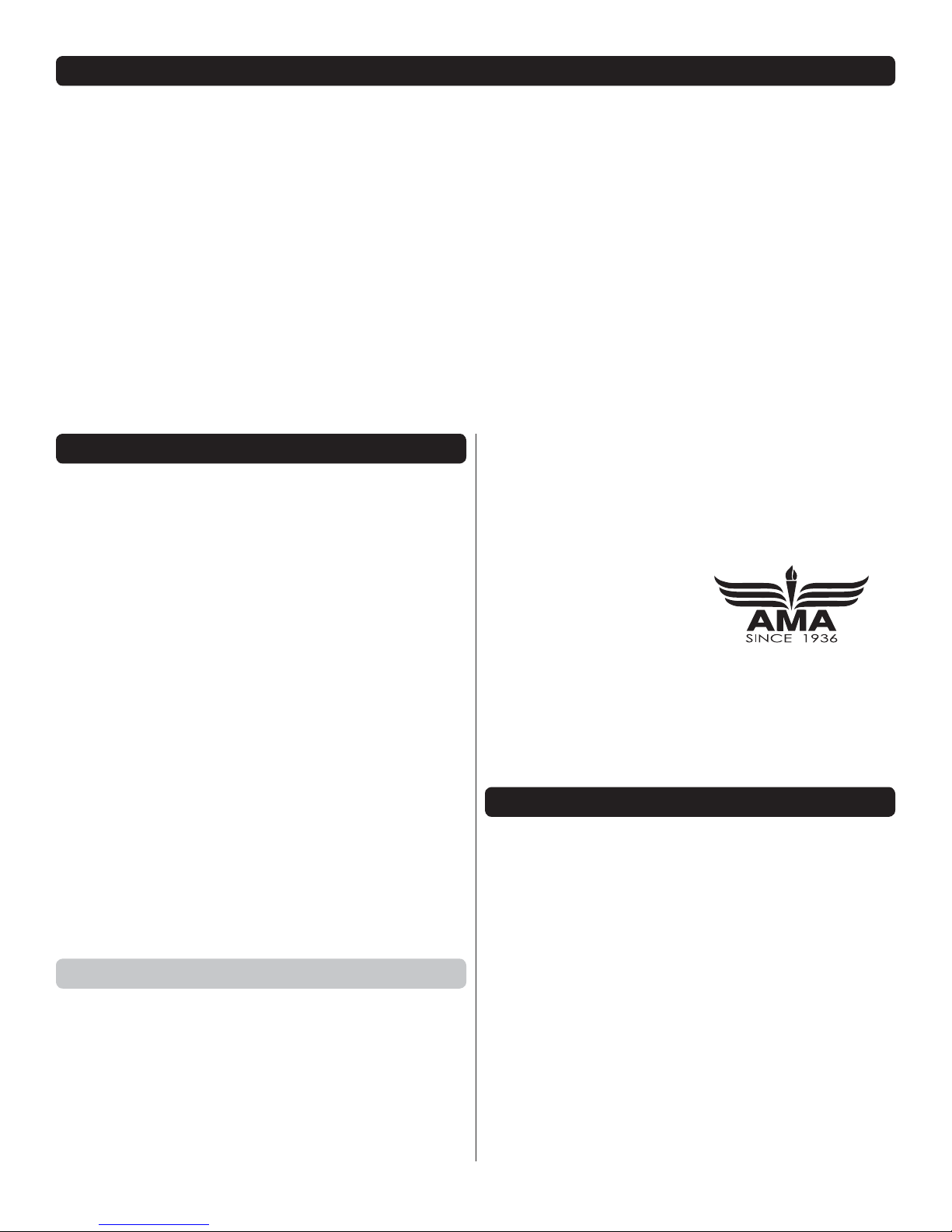
❏2. Insert the square elevator joiner into the pocket of one
of the horizontal stabilizer halves, being sure that the joiner
is fully seated in the pocket.
❏
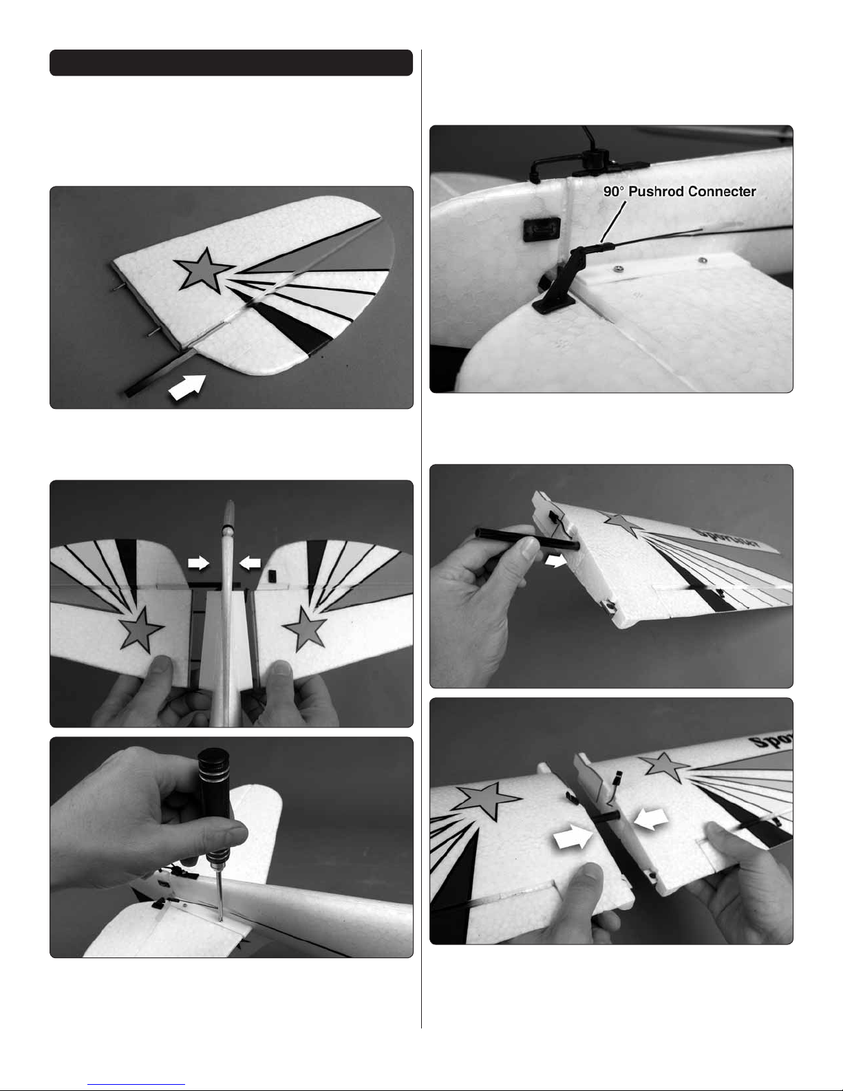
3. Slide the two horizontal stabilizer halves into the fuselage
so that the carbon pins installed in one side fit into the mating
holes in the other side and that the elevator joiner fits into
the other joiner pocket. Align the four holes in the molded
plastic stab saddle with the holes in the plywood plates on
the underside of the stab halves. Secure the stab halves to
the stab saddle using four 2x6mm screws.
❏4. Connect the elevator pushrod to the outer hole of the
elevator control horn and secure it using the 90 degree pushrod
connector that is attached to the pushrod.
❏5. Insert the carbon wing tube into one of the wing panels.
Slide the other panel onto the tube, being sure that the
aileron servo leads are aligned with the grooves at the
roots of the wings.
6
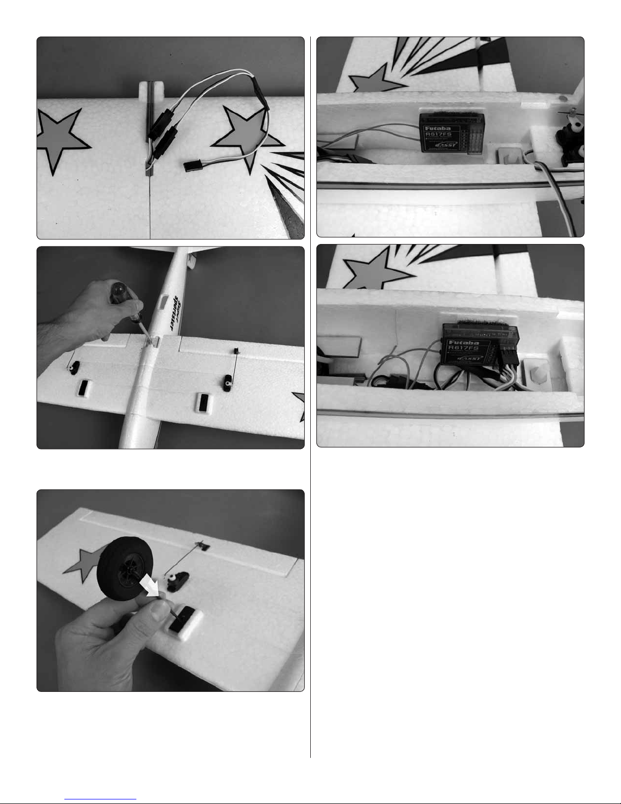
❏6. Connect the included Y-harness to the aileron servo leads.
Install the wing onto the fuselage using the nylon wing bolt.
❏7. Press the landing gear wires into the plastic landing
gear blocks as shown. Be sure that the landing gear is fully
seated in the blocks.
❏8. Use a piece from the included double-sided foam tape
to attach your receiver to the side of the fuselage as shown.
Connect the elevator servo, rudder servo, aileron servos and
ESC to the receiver. If you have installed a 2.4GHz receiver,
tape the receiver antennas to the side of the fuselage in the
orientation described in your radio manual. An FM receiver
antenna should be routed out the cool air exit hole on the
underside of the fuselage and taped to the underside of the fuse.

7
❏9. Install the prop adapter shaft, prop adapter hub and
spinner backplate onto the motor shaft. Fit the propeller onto
the shaft and secure it with the prop washer and prop nut. Be
sure to adequately tighten the prop nut.
❏10. Install the spinner cone onto the backplate using the
included screws.
❏11. Apply a piece of the included self-adhesive hook and
loop material to the battery tray and a mating piece to your
flight battery.Test fit the battery onto the battery tray.The exact
position of the battery on the tray will be determined when
you balance the plane. Depending on the battery you have
chosen, you may need to use a hobby knife to cut relief slots
in the sides of the fuselage for the battery wires.
GET THE MODEL READY TO FLY
Arming the ESC & Safe-Start Function
SAFE-START:As a safety precaution to prevent themotor from
rotating when the battery is first connected, you must “arm”
the ESC every time you connect the battery.The propeller will
NOT rotate until the ESC is armed.ALWAYS take care to keep
the propeller clear of yourself, others or objects WHENEVER
the ESC is connected to the battery!
❏1. Turn the transmitter’s power on.
❏2. Move the throttle stick to the minimum or idle position
(towards you).
❏3. Connect a fully charged battery to the ESC. The motor
will beep once to confirm the beginning of the arming routine.
❏4. If the ESC emits continuous high pitched beeps when
the throttle is moved to the idle position, disconnect the ESC
from the battery, change the position of the throttle reversing
switch on the transmitter and repeat the arming procedure
starting with step 1.
❏5. Move the throttle stick to full throttle (away from you).
The motor will again beep one time.
❏6. Move the throttle stick back to the idle position (towards
you) and the motor will beep twice to confirm the completion
of the arming routine.The ESC is now “armed”, and the motor
WILL ROTATE anytime the throttle stick is advanced beyond
the idle position.
Check the Control Directions
❏1.Turn on the transmitter and receiver and center the trims.
If necessary, remove the servo arms from the servos and
reposition them so they are centered. Reinstall the screws
that hold on the servo arms.
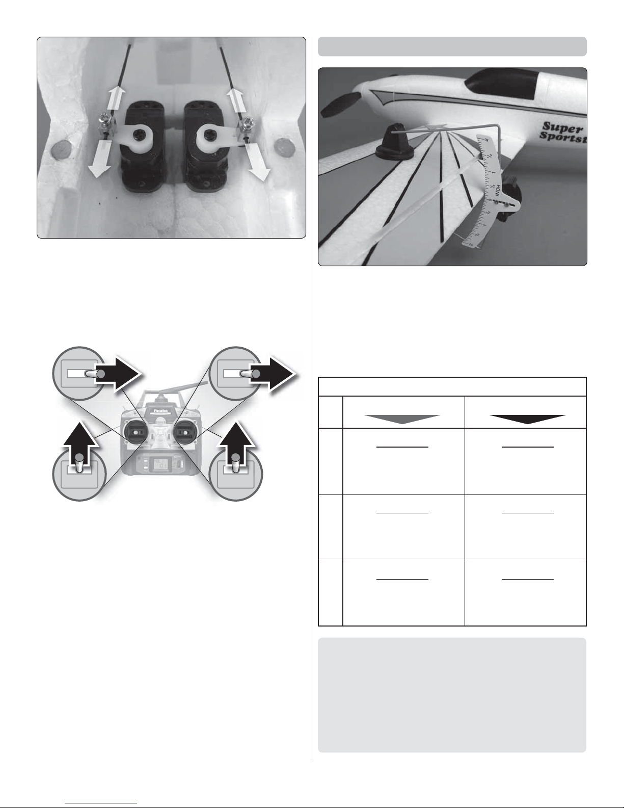
❏2. With the transmitter and receiver still on, use a straight
edge as shown to check all the control surfaces to see if they
are centered.
8
❏3. If necessary, adjust the pushrod positions in the screw
lock connectors to center the control surfaces.
FULL
THROTTLE
RUDDER
MOVES
RIGHT
ELEVATOR
MOVES DOWN
RIGHT AILERON MOVES UP
LEFT AILERON
MOVES DOWN
4-CHANNEL RADIO SETUP (STANDARD MODE 2)
❏4. Make certain that the control surfaces and the throttle
respond in the correct direction as shown in the diagram. If any
of the controls respond in the wrong direction, use the servo
reversing in the transmitter to reverse the servos connected to
those controls. Be certain the control surfaces have remained
centered. Adjust if necessary.
Set the Control Throws
Use a Great Planes AccuThrow (or a ruler) to accurately
measure and set the control throw of each control surface
as indicated in the chart that follows. If your radio does not
have dual rates, we recommend setting the throws at the low
rate setting.
NOTE: The throws are measured at the widest part of the
elevators, rudder and ailerons.
These are the recommended control surface throws:
ELEVATORRUDDERAILERONS
LOW RATE
1/4"
[6mm]
7°
Up & Down
7/32"
[6mm]
9°
Up & Down
5/8"
[16mm]
14°
Right & Left
HIGH RATE
9/16"
[14mm]
16°
Up & Down
5/16"
[8mm]
13°
Up & Down
7/8"
[22mm]
19°
Right & Left
IMPORTANT: The Super Sportster EPO has been
extensively flown and tested to arrive at the throws at
which it flies best. Flying your model at these throws will
provide you with the greatest chance for successful first
flights. If, after you have become accustomed to the way
the Super Sportster EPO flies, you would like to change
the throws to suit your taste, that is fine. However, too much
control throw could make the model difficult to control, so
remember, “more is not always better.”
9
Balance the Model (C.G.)
More than any other factor, the C.G. (balance point) can
have the greatest effect on how a model flies, and may
determine whether or not your first flight will be successful.
If you value this model and wish to enjoy it for many flights,
DO NOT OVERLOOKTHIS IMPORTANT PROCEDURE.
A model that is not properly balanced will be unstable and
possibly unflyable.
At this stage the model should be in ready-to-fly condition
with all of the systems in place including the brushless motor,
landing gear, the radio system and battery pack.
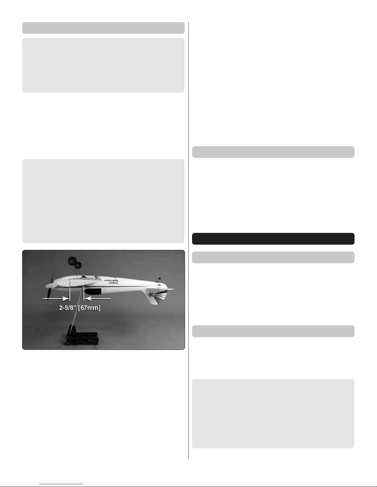
❏1. Use a felt-tip pen or 1/8" [3mm]-wide tape (do not apply
tape over the trim scheme!) to accurately mark the C.G. on
the top of the wing on both sides of the fuselage. The C.G. is
located 2-5/8" [67mm] back from the leading edge of the wing.
This is where your model should balance for the first flights.
Later, you may wish to experiment by shifting the C.G. up
to 3/4" [19mm] forward or 3/8" [9.5mm] back to change the
flying characteristics. Moving the C.G. forward may improve
the smoothness and stability, but the model may then
require more speed for takeoff and make it more difficult
to slow for landing. Moving the C.G. aft makes the model
more maneuverable, but could also cause it to become too
difficult to control. In any case, start at the recommended
balance point and do not at any time balance the model
outside the specified range.
❏2. With the wing attached to the fuselage, all parts of the
model installed (ready to fly) and battery installed, place the
model upside-down on a Great Planes CG Machine, or lift it
upside-down at the balance point you marked.
❏3. If the tail drops, the model is “tail heavy” and the battery
pack must be shifted forward or weight must be added to the
nose to balance. If the nose drops, the model is “nose heavy”
and the battery pack must be shifted aft or weight must be
added to the tail to balance. If possible, relocate the battery
pack and receiver to minimize or eliminate any additional
ballast required. If additional weight is required, use Great
Planes (GPMQ4485) “stick-on” lead. A good place to add
stick-on nose weight is to the firewall (don’t attach weight
to the cowl—it is not intended to support weight). Begin by
placing incrementally increasing amounts of weight on the
bottom of the fuse over the firewall until the model balances.
Once you have determined the amount of weight required, it
can be permanently attached. If required, tail weight may be
added by cutting open the bottom of the fuse and gluing it
permanently inside.
Note: Do not rely upon the adhesive on the back of the lead
weight to permanently hold it in place. Over time, the adhesive
may fail and cause the weight to fall off. Use #2 sheet metal
screws, RTV silicone or epoxy to permanently hold the weight
in place.
❏4. IMPORTANT: If you found it necessary to add any weight,
recheck the C.G. after the weight has been installed.
Balance the Model Laterally
❏1. With the wing level, have an assistant help you lift the
model by the motor propeller shaft and the bottom of the fuse
under the TE of the fin. Do this several times.
❏2. If one wing always drops when you lift the model, it means
that side is heavy. Balance the airplane by adding weight to the
other wing tip. An airplane that has been laterally balanced
will track better in loops and other maneuvers.
PREFLIGHT
Identify Your Model
No matter if you fly at an AMA sanctioned R/C club site or if
you fly somewhere on your own, you should always have your
name, address, telephone number and AMA number on or
inside your model. It is required at all AMA R/C club flying sites
and AMA sanctioned flying events. Fill out the identification
tag on page 12 and place it on or inside your model.
Charge the Batteries
Follow the battery charging instructions that came with your
radio control system to charge the batteries.You should always
charge your transmitter battery the night before you go flying,
and at other times as recommended by the radio manufacturer.
CAUTION: Unless the instructions that came with your
radio system state differently, the initial charge on new
transmitter batteries should be done for 15 hours using
the slow-charger that came with the radio system.This
will “condition” the batteries so that the next charge may
be done using the fast-charger of your choice. If the initial
charge is done with a fast-charger the batteries may not
reach their full capacity and you may be flying with batteries
that are only partially charged.

10
Balance Propellers
Carefully balance your propeller and spare propellers before
you fly. An unbalanced prop can be the single most significant
cause of vibration that can damage your model. Not only will
motor mounting screws loosen, possibly with disastrous effect,
but vibration may also damage your radio receiver and battery.
We use a Top Flite Precision Magnetic Prop Balancer
(TOPQ5700) in the workshop and keep a Great Planes
Fingertip Prop Balancer (GPMQ5000) in our flight box.
Range Check
Ground check the operational range of your radio before the
first flight of the day. With the transmitter antenna collapsed
and the receiver and transmitter on, you should be able to walk
at least 100 feet away from the model and still have control
(follow the instructions that came with your radio if you are using
a 2.4GHz system). Have an assistant stand by your model
and, while you work the controls, tell you what the control
surfaces are doing. Repeat this test with the motor running
at various speeds with an assistant holding the model, using
hand signals to show you what is happening. If the control
surfaces do not respond correctly, do not fly! Find and correct
the problem first. Look for loose servo connections or broken
wires, corroded wires on old servo connectors, poor solder
joints in your battery pack or a defective cell, or a damaged
receiver crystal from a previous crash.
MOTOR SAFETY PRECAUTIONS
Failure to follow these safety precautions may result
in severe injury to yourself and others.
Get help from an experienced pilot when learning to operate
motors.
Use safety glasses when running motors.
Do not run the motor in an area of loose gravel or sand; the
propeller may throw such material in your face or eyes.
Keep your face and body as well as all spectators away from
the plane of rotation of the propeller as you run the motor.
Keep these items away from the prop: loose clothing, shirt
sleeves, ties, scarves, long hair or loose objects such as
pencils or screwdrivers that may fall out of shirt or jacket
pockets into the prop.
The motor gets hot! Do not touch it during or right after operation.
LITHIUM BATTERY HANDLING AND USAGE
WARNING!! Read the entire instruction sheet included with
your battery. Failure to follow all instructions could cause
permanent damage to the battery and its surroundings,
and cause bodily harm!
• ONLY use a Li-Po approved charger. NEVER use a NiCd/
NiMH peak charger!
• NEVER charge in excess of 4.20V per cell.
• ONLY charge through the “charge” lead. NEVER charge
through the “discharge” lead.
• NEVER charge at currents greater than 1C.
• ALWAYS set charger’s output volts to match battery volts.
• ALWAYS charge in a fireproof location.
• NEVER trickle charge.
• NEVER allow the battery temperature to exceed 150° F
(65° C).
• NEVER disassemble or modify pack wiring in any way
or puncture cells.
• NEVER discharge below 2.5V per cell.
• NEVER place on combustible materials or leave unattended
during charge or discharge.
• ALWAYS KEEP OUT OF REACH OF CHILDREN.
• NEVER charge the battery in the plane.
• ALWAYS remove the battery from the plane after a crash.
Set it aside in a safe location for at least 20 minutes. If the
battery is damaged in the crash it could catch fire. If the
battery starts to swell, quickly move the battery to a safe
location, preferably outside: Place it in a bucket, covering
the battery with sand.
AMA SAFETY CODES
Read and abide by the following excerpts from the Academy
of Model Aeronautics Safety Code. For the complete Safety
Code refer to Model Aviation magazine, the AMA web site or
the Code that came with your AMA license.
General
1) I will not fly my model aircraft in sanctioned events, air shows,
or model flying demonstrations until it has been proven to be
airworthy by having been previously, successfully flight tested.
2) I will not fly my model aircraft higher than approximately
400 feet within 3 miles of an airport without notifying the

11
airport operator. I will give right-of-way and avoid flying in the
proximity of full-scale aircraft. Where necessary, an observer
shall be utilized to supervise flying to avoid having models fly
in the proximity of full-scale aircraft.
3) Where established, I will abide by the safety rules for the
flying site I use, and I will not willfully and deliberately fly my
models in a careless, reckless and/or dangerous manner.
5) I will not fly my model unless it is identified with my name
and address or AMA number, on or in the model. Note: This
does not apply to models while being flown indoors.
7) I will not operate models with pyrotechnics (any device that
explodes, burns, or propels a projectile of any kind).
Radio Control
1) I will have completed a successful radio equipment ground
check before the first flight of a new or repaired model.
2) I will not fly my model aircraft in the presence of spectators
until I become a qualified flier, unless assisted by an
experienced helper.
3) At all flying sites a straight or curved line(s) must be
established in front of which all flying takes place with the
other side for spectators. Only personnel involved with flying
the aircraft are allowed at or in the front of the flight line.
Intentional flying behind the flight line is prohibited.
4) I will operate my model using only radio control frequencies
currently allowed by the Federal Communications Commission.
5) I will not knowingly operate my model within three miles
of any pre-existing flying site except in accordance with
the frequency sharing agreement listed [in the complete
AMA Safety Code].
9) Under no circumstances may a pilot or other person touch
a powered model in flight; nor should any part of the model
other than the landing gear, intentionally touch the ground,
except while landing.
CHECK LIST
During the last few moments of preparation your mind may
be elsewhere anticipating the excitement of the first flight.
Because of this, you may be more likely to overlook certain
checks and procedures that should be performed before the
model is flown.To help avoid this, a check list is provided to
make sure these important areas are not overlooked. Many
are covered in the instruction manual, so where appropriate,
refer to the manual for complete instructions. Be sure to
check the items off as they are completed (that’s why it’s
called a check list!).
❏1. Check the C.G. according to the measurements provided
in the manual.
❏2. Be certain the receiver is securely mounted in the fuse.
Simply stuffing it into place with foam rubber is not sufficient.
❏3. Extend your receiver antenna or secure dual receivers
inside the fuselage as described in the instructions.
❏4. Balance your model laterally as explained in the
instructions.
❏5. Confirm that all controls operate in the correct direction
and the throws are set up according to the manual.
❏6. Make sure the servo wires andY-harness do not interfere
with other systems (servo arms, pushrods, etc.).
❏7. Balance your propeller (and spare propellers).
❏8. Tighten the propeller nut and spinner.
❏
9. Place your name, address, AMA number and telephone
number on or inside your model.
❏10. If you wish to photograph your model, do so before
your first flight.
❏11. Range check your radio when you get to the flying field.
FLYING
The Super Sportster EPO is a great-flying model that flies
smoothly and predictably. The Sportster does not, however,
possess the self-recovery characteristics of a primary R/C
trainer and should be flown only by experienced R/C pilots.
CAUTION (THIS APPLIES TO ALL R/C AIRPLANES): If,
while flying, you notice an alarming or unusual sound such
as a low-pitched “buzz,” this may indicate control surface
flutter. Flutter occurs when a control surface (such as an
aileron or elevator) or a flying surface (such as a wing or
stab) rapidly vibrates up and down (thus causing the noise).
In extreme cases, if not detected immediately, flutter can
actually cause the control surface to detach or the flying
surface to fail, thus causing loss of control followed by
an impending crash. The best thing to do when flutter is
detected is to slow the model immediately by reducing
power, then land as soon as safely possible. Identify which
surface fluttered (so the problem may be resolved) by
checking all the servo grommets for deterioration or signs of
vibration. Make certain all pushrod linkages are secure and
free of play. If it fluttered once, under similar circumstances
it will probably flutter again unless the problem is fixed.
Some things which can cause flutter are; Excessive hinge
gap; Not mounting control horns solidly; Poor fit of clevis
pin in horn; Side-play of wire pushrods caused by large
bends; Excessive free play in servo gears; Insecure servo
mounting; and one of the most prevalent causes of flutter;
Flying an over-powered model at excessive speeds.

12
Takeoff
Before you get ready to takeoff, see how the model handles
on the ground by doing a few practice runs at low speeds on
the runway. Hold “up” elevator to keep the tail wheel on the
ground. If necessary, adjust the tail wheel so the model will
roll straight down the runway. If you need to calm your nerves
before the maiden flight, shut the motor down and bring the
model back into the pits.Top off your batteries, then check all
fasteners and control linkages for peace of mind.
Remember to takeoff into the wind. When you’re ready, point
the model straight down the runway, hold a bit of up elevator
to keep the tail on the ground to maintain tail wheel steering,
then gradually advance the throttle. As the model gains
speed decrease up elevator, allowing the tail to come off the
ground. One of the most important things to remember with
a tail dragger is to always be ready to apply right rudder to
counteract motor torque. Gain as much speed as your runway
and flying site will practically allow before gently applying up
elevator, lifting the model into the air. At this moment it is likely
that you will need to apply more right rudder to counteract
motor torque. Be smooth on the elevator stick, allowing the
model to establish a gentle climb to a safe altitude before
turning into the traffic pattern.
Flight
For reassurance and to keep an eye on other traffic, it is a
good idea to have an assistant on the flight line with you. Tell
him to remind you to throttle back once the plane gets to a
comfortable altitude. While full throttle is usually desirable for
takeoff, most models fly more smoothly at reduced speeds.
Take it easy with the Sportster for the first few flights, gradually
getting acquainted with it as you gain confidence. Adjust the
trims to maintain straight and level flight. After flying around
for a while and while still at a safe altitude with plenty of
battery charge, practice slow flight and execute practice
landing approaches by reducing the throttle to see how the
model handles at slower speeds. Add power to see how
the model climbs as well. Continue to fly around, executing
various maneuvers and making mental notes (or having your
assistant write them down) of what trim or C.G. changes may
be required to fine tune the model so it flies the way you like.
Mind your battery charge, but use this first flight to become
familiar with your model before landing.
Landing
To initiate a landing approach, lower the throttle while on the
downwind leg. Allow the nose of the model to pitch downward
to gradually bleed off altitude. Continue to lose altitude, but
maintain airspeed by keeping the nose down as you turn onto
the crosswind leg. Make your final turn toward the runway (into
the wind) keeping the nose down to maintain airspeed and
control. Level the attitude when the model reaches the runway
threshold, modulating the throttle as necessary to maintain
your glide path and airspeed. If you are going to overshoot,
smoothly advance the throttle (always ready on the right rudder
to counteract torque) and climb out to make another attempt.
When you’re ready to make your landing flare and the model
is a foot or so off the deck, smoothly increase up elevator until
it gently touches down. Once the model is on the runway and
has lost flying speed, hold up elevator to place the tail on the
ground, regaining tail wheel control.
One final note about flying your model. Have a goal or flight
plan in mind for every flight. This can be learning a new
maneuver(s), improving a maneuver(s) you already know,
or learning how the model behaves in certain conditions
(such as on high or low rates). This is not necessarily to
improve your skills (though it is never a bad idea!), but more
importantly so you do not surprise yourself by impulsively
attempting a maneuver and suddenly finding that you’ve run
out of time, altitude or airspeed. Every maneuver should be
deliberate, not impulsive. For example, if you’re going to do a
loop, check your altitude, mind the wind direction (anticipating
rudder corrections that will be required to maintain heading),
remember to throttle back at the top, and make certain you
are on the desired rates (high/low rates). A flight plan greatly
reduces the chances of crashing your model just because
of poor planning and impulsive moves. Remember to think.
Have a ball! But always stay in control
and fly in a safe manner.
Good luck and great flying!
This model belongs to:
Name
Address
City, State, Zip
Phone Number
AMA Number
Table of contents
Other electrifly Toy manuals


Popular Toy manuals by other brands


Trix
Trix E 44 Series manual

Little Tikes
Little Tikes Sparkle Bay Flicker Fish quick start

LEGO
LEGO The Ninjago movie 70609 Assembly instruction

Badger Basket
Badger Basket 10.0/0714/TG Assembly and use instructions

Eduard
Eduard P-3 Orion bomb bay quick start guide

MGA Entertainment
MGA Entertainment L.O.L. Surprise! O.M.G. Winter Disco 2019 Collector Edition Crystal Star... manual