Electriq Power WND-WR-MB User manual

Quick Install Guide
for the Electriq Power
PowerMeter
Model Number:
WND-WR-MB
V. 043120
The Smart Home Battery Solution
IMPORTANT SAFETY WARNINGS
PLEASE READ ALL INSTRUCTIONS AND CAUTIONARY MARKINGS ON
THE UNIT AND THIS MANUAL BEFORE USING THE POWERMETER.
AND, STORE THIS USER MANUAL WHERE IT CAN BE ACCESSED EASILY.
Safety Symbols
Read, understand, and follow all instructions
including warnings and precautions before
installing and using the product.
Potential Shock Hazard from Dangerous High
Voltage.
Functional ground; should be connected to earth
ground if possible, but is not required for safety
grounding.
UL Listing mark for U.S.A. and Canada.
FCC Mark. This logo indicates compliance with part
15 of the FCC rules.
Complies with the regulations of the European
Union for Product Safety and Electro-Magnetic
Compatibility.
• Low Voltage Directive – EN 61010-1:2010 (3rd Edition)
• EMC Directive – EN 61326-1:2006 Industrial Locations
This indicates an AC voltage.
1. Precautions
1.1 Symbols
• Only qualified personnel or licensed electricians should install
the PowerMeter. The mains voltages of 120 to 600 Vac can be
lethal!
• Follow all applicable local and national electrical and safety
codes.
Important Safety Warnings
Important Safety Warnings
• The terminal block screws are not insulated. Do not contact
metal tools to the screw terminals if the circuit is live!
• Verify that circuit voltages and currents are within the proper
range for the meter model.
• Use only CTs provided in the PowerMeter kit.
• Protect the line voltage conductors to the meter with fuses or
circuit breakers (not needed for the neutral or ground wires).
• Disconnect equipment from HAZARDOUS LIVE voltages before
access.
• If the meter is not installed correctly, the safety protections
may be impaired.
2. Overview
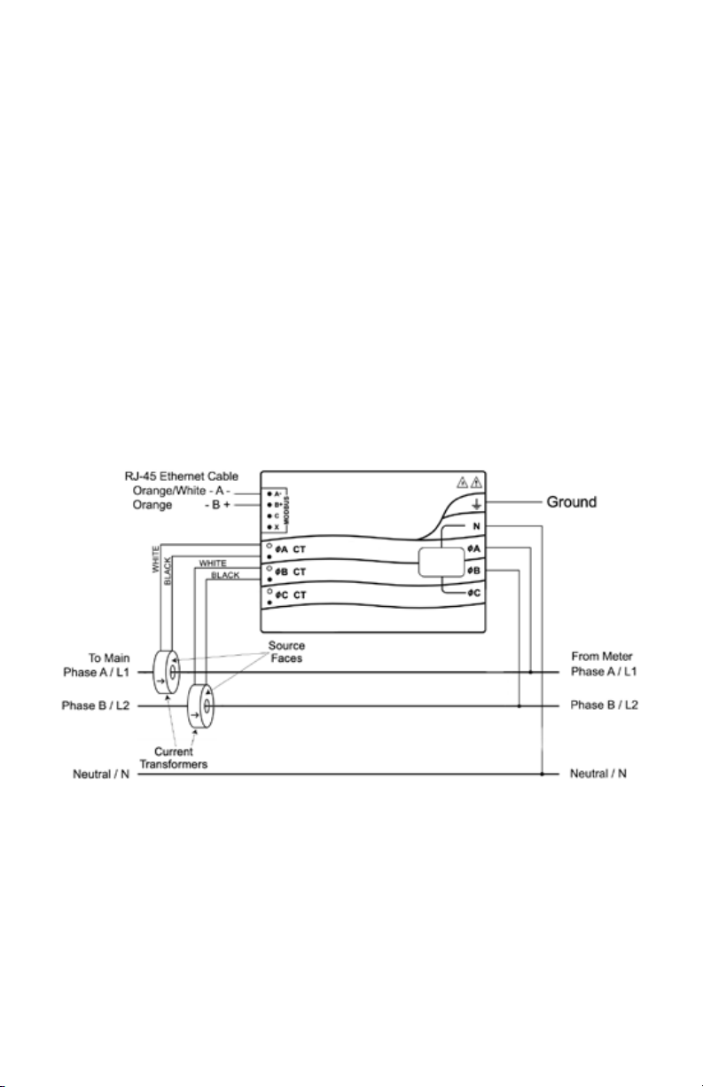
Figure 1: US Single-Phase Three-Wire with Neutral

3. Installation
3.1 Installation Checklist
See the sections referenced below for installation details.
qTurn o power before making line voltage connections.
qMount the meter (see 3.2).
qConnect circuit breakers or fuses and disconnects (see 3.3.1).
qConnect the line voltage wires to the meter’s green terminal
block (see 3.3.2).
qMount the CTs around the line conductors. Make sure the CTs
face the source (see 3.4).
qConnect the twisted white and black wires from the CTs to the
black terminal block on the meter, matching the wire colors to
the white and black dots on the meter label (s ee 3.4.1).
qCheck that the CT phases match the line voltage phases
(see 3.4).
qConnect the output terminals of the meter to the monitoring
equipment (see 3.5).
qCheck that all the wires are securely installed in the terminal
blocks by tugging on each wire.
qTurn on power to the meter.
3.2 Mounting
qProtect the meter from temperatures below –40°C (–40°F) or
above 75°C (167°F), excessive moisture, dust, salt spray, or other
contamination, using a NEMA rated enclosure if necessary. The
meter requires an environment no worse than pollution degree
2 (normally only non-con- ductive pollution; occasionally, a
temporary conductivity caused by condensation).
qThe meter must be installed in an electrical service panel or an
enclosure.
qDo not use the meter as a drilling guide; the drill chuck can
damage the screw terminals and metal shavings may fall into
the connectors. The meter has two mounting holes spaced
5.375 in. (137 mm) apart (center-to-center). These mounting
holes are normally obscured by the detachable screw terminals.
Remove the screw terminals to mark the hole positions and
mount the meter. Self-tapping #8 sheet metal screws are
included. Don’t over-tighten the screws, as long-term stress on
the case can cause cracking.
Installation

Installation
3.3 Connect Voltage Terminals
3.3.1 Circuit Protection
The PowerMeter is considered “permanently connected equipment”
and requires a disconnect means (circuit breaker, switch, or disconnect)
and overcurrent protection (fuse or circuit breaker).
The meter only draws 10-30 milliamps, so the rating of any switches,
disconnects, fuses, or circuit breakers is determined by the wire gauge,
the mains voltage, and the current interrupting rating required.
qThe disconnect or circuit breaker must be clearly marked,
suitably located, and easily reached.
qUse circuit breakers or fuses rated for 20 amps or less.
qUse ganged circuit breakers when monitoring more than one
line voltage.
qThe circuit breakers or fuses must protect the mains terminals
labeled ØA and ØB. In the rare cases where neutral has
overcurrent protection, then the overcurrent protection
device must interrupt both neutral and the ungrounded
conductors simultaneously.
qThe circuit protection / disconnect system must meet IEC 60947
1 and IEC 60947-3, as well as all national and local electrical
codes.
3.3.2 Line Wiring
qAlways turn o power before connecting the line voltage
inputs to the meter.
qFor the line voltage wires, Electriq Power recommends 18 to 12
AWG stranded wire, type THHN, MTW, or THWN, 600 V.
qUse copper conductors only. The screw terminals are only rated
for copper wire.
qDo not place more than one wire in a screw terminal; use
additional wire nuts or terminal blocks if needed.
The screw terminals handle wire up to 12 AWG. Connect each voltage
line to the green terminal block as shown in Figure 1 above. After the
voltage lines have been connected, make sure both terminal blocks are
fully seated in the meter.
Connect each line voltage to the appropriate phase; also connect
ground and neutral.

Installation
3.4 Connect Current Transformers
qWARNING: To reduce the risk of electric shock, always open or
disconnect circuit from power- distribution system or service of
the building before installing or servicing current transformers.
qUse only the CTs provided in the meter kit. They are matched
and configured for the meter. The CTs are not suitable for Class
2 wiring methods and must be treated as Class 1 wires.
qSecure each current transformer and route the lead wires so
that they do not directly contact live terminals or buses.
qDo not install current transformers where they would: 1) exceed
75 percent of the wiring space of any cross-sectional area within
the equipment, 2) would block ventilation openings, or 3) would
be in an area of breaker arc venting.
qBe careful to match the CTs with the voltage phases. Make sure
the ØA CT is measuring the current on the same phase being
monitored by the ØA voltage input, and the same for phase B.
Use the supplied colored labels or colored tape to identify the
CT leads.
qFind the source arrow or label “THIS SIDE TOWARD GRID”
on the CT and face/point toward the source of current.
Install the CTs around the conductor to be measured and connect the
CT leads to the meter as shown in Figure 1 above.
Split-core CTs can be opened for installation around a conductor. A
nylon cable tie may be secured around the CT to prevent inadvertent
opening.
CTs are directional. If they are mounted backwards or with their white
and black wires swapped the measured power will be negative.
3.4.1 CT Wiring
The current transformers connect to the six position black screw
terminal block. Connect the white and black CT wires to the meter
terminals marked ØA CT and ØB CT (see Figure 1 above). Excess
length may be trimmed from the wires if desired. Connect each CT with
the white wire aligned with the white dot on the label, and the black
wire aligned with the black dot. Note the order in which the phases are
connected, as the line voltage phases must match the current phases
for accurate power measurement.

Installation
3.5 Connect the Modbus Signals
qRoute the provided CAT6 cable (black 4-pin connector) from
the main panel / PowerMeter location to the inverter panel
(RJ-45 male end).
qReplace the existing USB/RS-485 cable that connects the
PowerHub to the inverter with the one provided in the
PowerMeter kit (add the RJ-45 coupler on the inverter side).
qPlug the RJ-45 male end of cable into the coupler on the USB
RS-485 cable that connects to inverter (see Figure 2).
qPlug the 4-pin black connector into the RS-485/Modbus
socket on the PowerMeter (see Figure 1).
3.6 Maintenance and Repair
The PowerMeter requires no maintenance. It is not user serviceable and
there are no replaceable parts except the pluggable screw terminals.
There are no diagnostic tests that can be performed by the installer.
In the event of any failure, the meter must be returned for service
(contact Electriq Power Support for an RMA at support@electriqpower.
com).
Figure 2: USB/RS485 cable with RJ45 connector and barrow
Inverter

www.electriqpower.com
14451 Catalina Street
San Leandro, CA 94577
Table of contents


