manuals.online logo
Brands
  1. Home
  2. •
  3. Brands
  4. •
  5. Zenner
  6. •
  7. Measuring Instrument
  8. •
  9. Zenner zelsius User manual

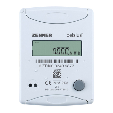
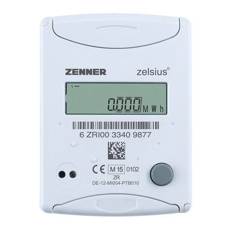
Zenner zelsius User manual

Operating manual Operating manual
Heat meter zelsius®Heat meter zelsius®
... because every drop of water counts. ... because every drop of water counts.
Dimensions
Dimensions
Height : H mm
E max mm 80
18,5
Width heat computer: mm 72
Length heat computer: mm 100
Overall length EAS body L mm 110 (130)
Electronic Heat Meter
zelsius®
Heat meter 2’’ with coaxial-measuring capsule
Qn 2,5 / 1,5 / 0,6 m³/h
Please hand out this manual to the end customer!
Subject to modifications and errors excepted!
N°98W033_020204_GB
ZENNER GmbH & Co. KGaA; Römerstadt 4; 66121 Saarbrücken; Germany
Tel.: + 49 681 / 99676-0; Fax: + 49 681 / 64394
www.zenner.de; info@zenner.d
e
E
L
H
5545
72
1
0
0
ZENNER GmbH & Co. KGaA; Römerstadt 4; 66121 Saarbrücken; Germany
Tel.: + 49 681 / 99676-0; Fax: + 49 681 / 64394
www.zenner.de; info@zenner.de
Operating manual Operating manual
Heat meter zelsius®Heat meter zelsius®
... because every drop of water counts. ... because every drop of water counts.
General information
Thank you for having purchased
zelsius®
one of the most modern heat meters
available on the market today.
A lot of helpful functions and menus will assist you in getting better acquainted with
your use of energy and your pattern of consumption.
With time, you will be able to save costs, because of having the possibility of control-
ling your own pattern of consumption.
Expressive symbols in the display and a simple user interface and menu navigation
also make working with zelsius
®
a pleasure (see the display overview also).
zelsius®is operated using a single colored button.
It is equipped with a long-life battery, designed for operation over one calibration
period, including a buffer time of at least a year.
Certification
The seal resp. the label with the year of first calibration is located on the front of the
heat meter. The calibration validity is 5 years (in Germany; other countries may have
different regulations).
Should the device be opened unauthorized guarantee and calibration validity of the
meter expire.
Interference potential
The heat meter is constructed to comply with the national and international require-
ments on interference resistance.
To avoid further interferences, no fluorescent tubes, switch boxes or consumers of
electricity, such as motors or pumps are to be installed in the vicinity of the meter
(minimum clearance 1 m). Cables from the meter may not be laid parallel to the line
voltage carrying cables (230V) (clearance at least 0,2 m).
Care instructions
Clean the plastic surface only with a damp cloth. Do not use any scrubbing or ag-
gressive detergents!!
Remote readout output (optional)
External counting inputs from pulse
counters can be accessed using the
option „remote readout output“ (see
the type plate on the side).
For the use of this option, a firmly
connected cable is included in deliv-
ery. You must take care of the exter-
nal circuits yourself (see drawing on
the right).
M-Bus (optional)
The name of the version is imprinted on the type plate, on the side of the device.
• Baud rate 9600/2400 switchable (optical interface 2400 Baud)
• Compliant with the standard according to EN 1434
• Connection of cable wires any
Data remote readout output
Load max. 30VDC / 20 mA
Switching output 1,2 Open Drain, n-canal FET
Cable D= 4 mm, 2 wires
Cable length 1,10 m (standard)
Internal output
circuit
External circuit
1
2
3-30 VDC
I max 20 mA
cable 2 wires
D= 4 mm, 1,10m
brown
blue
Remote readout output
The outputs emit a pulse with an output frequency of 1 Hz and a pulse with
factor of approx. 1:1.
t
p
t
p
3...30 V
0 V
400 ms < tp < 600 ms
Operating manual Operating manual
Heat meter zelsius®Heat meter zelsius®
... because every drop of water counts. ... because every drop of water counts.
Status Displays
The status messages display the operational status of the meter in an easily under-
standable manner (see table below).
Note :
The status messages in the table below only appear in the main display (en-
ergy)!
In all cases, in which the warning triangle represents a status message, you
should check first whether the problem is permanent or occurs only temporar-
ily.
If the symbol appears permanently, a service company should be called!
A few displays can be conditional upon the system and do not necessarily mean that
the meter is defect. The warning display disappears after a short period when the
system is operating properly.
Technical Data
* HC = heat computer
** VMU = volumetric measuring unit
Symbol Status Display Event / Reaction
Flow existent System is operating.
Indicator for a possible
defect! Always on If warning triangle appears
permanently, please notify a
service company.
Data transfer on the
interface
Only on when
data is being
transmitted
.and.. Emergency operation! Always on
Energy is still being displayed
and calculated correctly. All
other displays however, are
blocked and the button also
no longer reacts.
Notify service company
Type zelsius
Temperature range HC* °C 1 ...130
Temperature range VMU** °C 15 ... 90
Temperature difference
range Kelvin 3 ...100
Type of temperature sensor Pt 500
Temperature range sensor °C 0 ... 130 (Silicon)
Dimensions sensor mm 5,0 / 5,2 (cable 1,5 m)
Nominal flow rate Qp m³/h 0,6 1,5 2,5
Nominal diameter DN mm 15 15 20
Highest flow rate Qs m³/h 1,2 3,0 5,0
Transitional flow rate Qt
(Class A) l/h 120 150 250
Minimum flow Qmin (Class A) l/h 24 60 100
Nominal pressure bar 16
Media temperature VMU Tmax °C 90
Pressure loss at Qp bar
≤
0,25
Starting flow rate typical
Horizontal ca. l/h 4 4 6
Display range LC-Display 8 positions, 3 after comma
Battery V 3,0 (Lithium)
Battery life years ≥6
Protection class IP 54
Ambient temperature °C 0 ...55
Weight measuring capsule g ca. 680
Connecting thread capsule inch G 2 B
Display overview
Heat meter zelsius®
... because every drop of water counts.
Note:
According your meter’s
model, it’s displays can differ
in number and sequence
from those represented here.
A complete and detailed
operating manual can be
downloaded from our support
area under
http://www.zenner.de
Level 1 Level 2 Level 3
Energy (Main display)
Energy on S.R.D.
A change in level can take
place from any display in the
menu.
Type of sensor and
installation location
Volume
Date S.R.D.
Type number
Segment test
Consumption previous year
Monthly statistics
End of calibration validity
Supply temperature
Current monthly consumption
LL
HH
Date 1. Monthly value
LL
S
Energy to 1. Monthly value Current Time
Return temperature
Serial number
Date 2. Monthly value
Current Date
Further to the previous month
Temperature difference
Customer number (optional)
s
Error status
Flow rate
s
Software version
Legend:
s
Press button briefly (S), usually used to scroll from top to bottom. After the last menu display
has been reached, a jump is automatically made to the top (first) menu item (loop).
Actual power
LL
Press button for approx. 2 sec.(L), wait until the door symbol (upper right in the display)
appears and then release the button. Then the menu is updated resp. a jump is made to the
submenu.
s
s
Hold button (H) until the level is changed or a return from the submenus occurs.

Other Zenner Measuring Instrument manuals

Zenner MNK-MF-N User manual

Zenner

Zenner MNK-MF-N User manual

Zenner MC User manual

Zenner

Zenner MC User manual

Zenner Minolist User manual

Zenner

Zenner Minolist User manual

Zenner RTKD User manual

Zenner

Zenner RTKD User manual

Zenner zelsius C5-IUF User manual

Zenner

Zenner zelsius C5-IUF User manual

Zenner multidata User manual

Zenner

Zenner multidata User manual

Zenner L868 ID A User guide

Zenner

Zenner L868 ID A User guide

Zenner zelsius C5 -IUF User manual

Zenner

Zenner zelsius C5 -IUF User manual

Zenner Minomess MC User manual

Zenner

Zenner Minomess MC User manual

Zenner zelsius C5-ISF User manual

Zenner

Zenner zelsius C5-ISF User manual

Zenner CO2 INDICATOR L868 ID A User manual

Zenner

Zenner CO2 INDICATOR L868 ID A User manual

Zenner Minolist ER2 User manual

Zenner

Zenner Minolist ER2 User manual

Zenner RTKD User manual

Zenner

Zenner RTKD User manual

Zenner zelsius C5-IUF User manual

Zenner

Zenner zelsius C5-IUF User manual

Zenner zelsius C5-CMF User manual

Zenner

Zenner zelsius C5-CMF User manual

Zenner multipulse User manual

Zenner

Zenner multipulse User manual

Zenner IUWS Series User manual

Zenner

Zenner IUWS Series User manual

Zenner IUWS User manual

Zenner

Zenner IUWS User manual

Zenner zelsius C5-IUF User manual

Zenner

Zenner zelsius C5-IUF User manual

Zenner ZSU02 User manual

Zenner

Zenner ZSU02 User manual

Zenner WSD User manual

Zenner

Zenner WSD User manual

Zenner IUW Series User manual

Zenner

Zenner IUW Series User manual

Zenner zelsius C5-ISF User manual

Zenner

Zenner zelsius C5-ISF User manual

Zenner zelsius C5-ISF User manual

Zenner

Zenner zelsius C5-ISF User manual

Popular Measuring Instrument manuals by other brands

HART E018-P user manual

HART

HART E018-P user manual

Myron L PoolPro PS6FCE quick start guide

Myron L

Myron L PoolPro PS6FCE quick start guide

Minolta AUTOMETER VF - PART 3 manual

Minolta

Minolta AUTOMETER VF - PART 3 manual

Vernier GNM-BTA manual

Vernier

Vernier GNM-BTA manual

Powerfix Profi 288019 Operation and safety notes

Powerfix Profi

Powerfix Profi 288019 Operation and safety notes

Bender ISOMETER IR1575H manual

Bender

Bender ISOMETER IR1575H manual

Monacor ZM-100 instruction manual

Monacor

Monacor ZM-100 instruction manual

HP 8560A Service manual

HP

HP 8560A Service manual

Omicron CT SB2 user manual

Omicron

Omicron CT SB2 user manual

Pyxis ST-500 Operation manual

Pyxis

Pyxis ST-500 Operation manual

Bacharach Comfort Chek 400 Operation manual

Bacharach

Bacharach Comfort Chek 400 Operation manual

S+S Regeltechnik RHEASREG KLSW Operating Instructions, Mounting & Installation

S+S Regeltechnik

S+S Regeltechnik RHEASREG KLSW Operating Instructions, Mounting & Installation

BD PhoenixSpec user guide

BD

BD PhoenixSpec user guide

APPA A3 user manual

APPA

APPA A3 user manual

Spirax Sarco Colima Visco Installation and maintenance instructions

Spirax Sarco

Spirax Sarco Colima Visco Installation and maintenance instructions

VR Avionics TM1 Operational and installation manual

VR Avionics

VR Avionics TM1 Operational and installation manual

Dwyer Instruments PUX2 instruction manual

Dwyer Instruments

Dwyer Instruments PUX2 instruction manual

Rish Master 3430 operating manual

Rish

Rish Master 3430 operating manual

manuals.online logo
manuals.online logoBrands
  • About & Mission
  • Contact us
  • Privacy Policy
  • Terms and Conditions

Copyright 2025 Manuals.Online. All Rights Reserved.