3/8
TECHNICAL SPECIFICATIONS
STANDARDS
EN61000-6-4 Electromagnetic emissions, industrial environment.
EN61000-6-2 Electromagnetic immunity, industrial environment.
EN60950 Safety
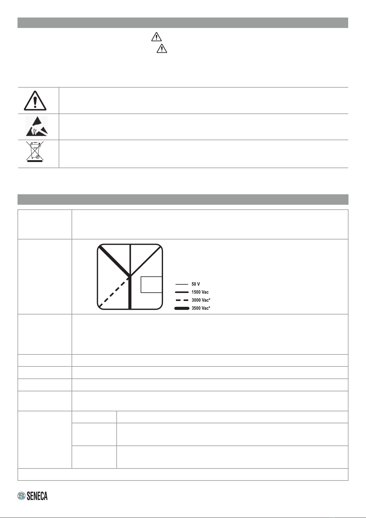
INSULATION
ENVIRONMENTAL
CONDITIONS
Temperature: -25°C ÷ +55°C
Humidity: 30% ÷ 90% non condensing.
Storage temperature: -30°C÷ + 85°C
Degree of protection: IP20
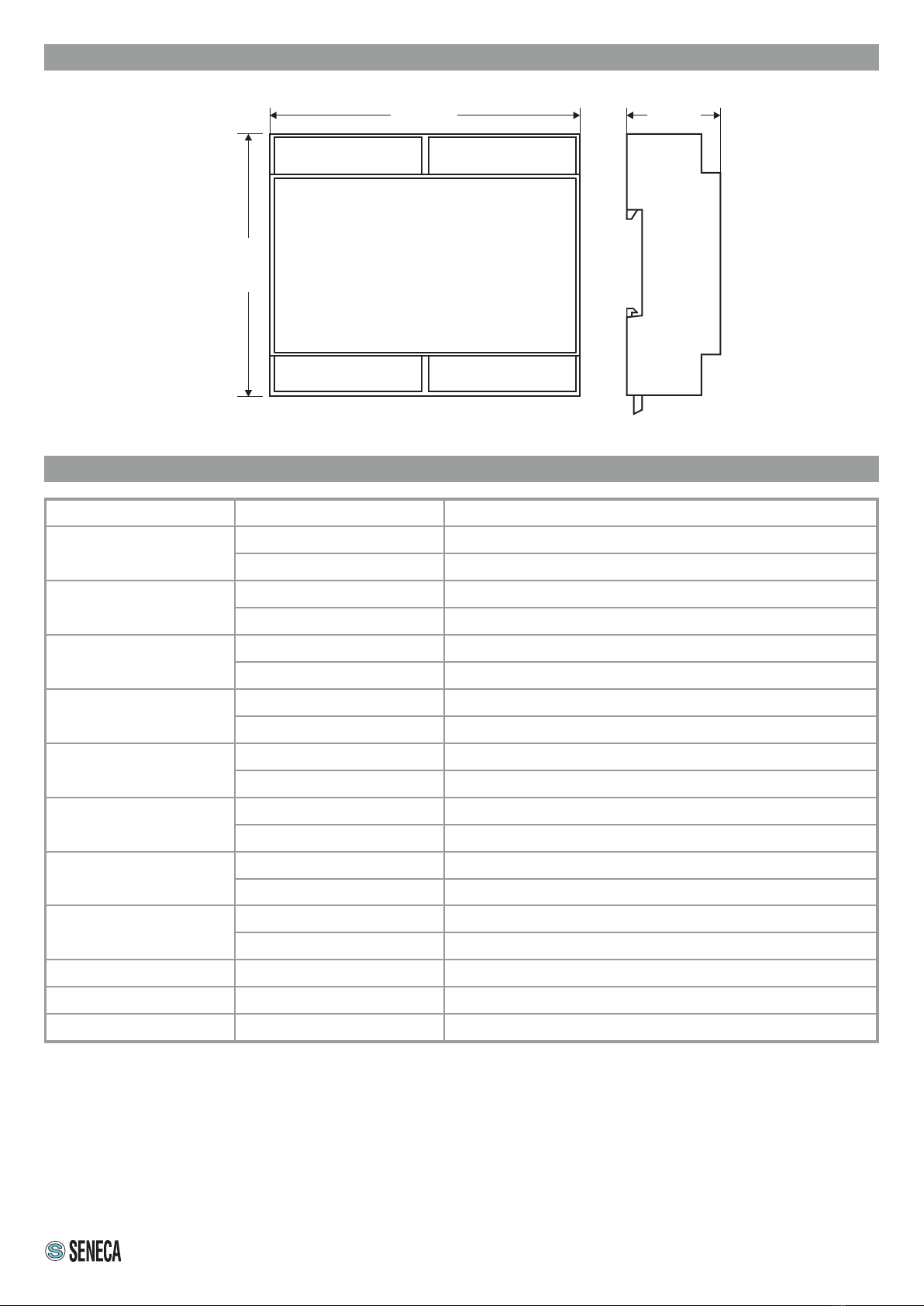
ASSEMBLY DIN rail 35mm IEC EN60715, wall or panel with screws.
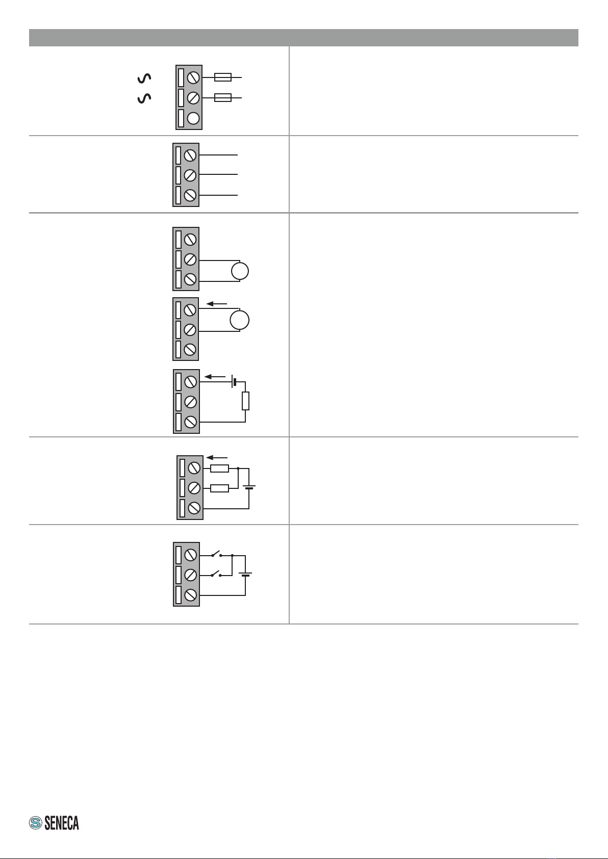
CONNECTIONS Screw terminals 5 mm, 7.5 mm and 3.5 mm pitch (RS485), cable with section <2.5 mm2
POWER SUPPLY Voltage: 90 ÷ 264 Vac @ 50 ÷ 60 Hz, max. absorption 2.8 W, 5.4 VA
COMMUNICATION
PORTS
RS485: Baud rate: 1200 ÷ 115200 baud (for further information see the user manual).
USB: Micro-USB port for programming
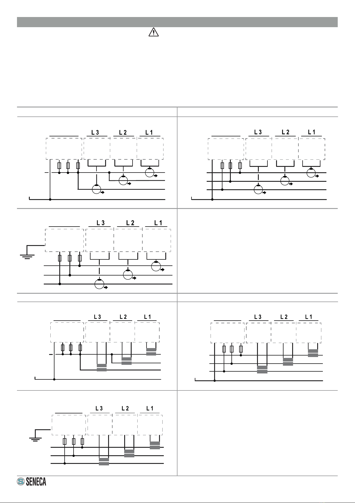
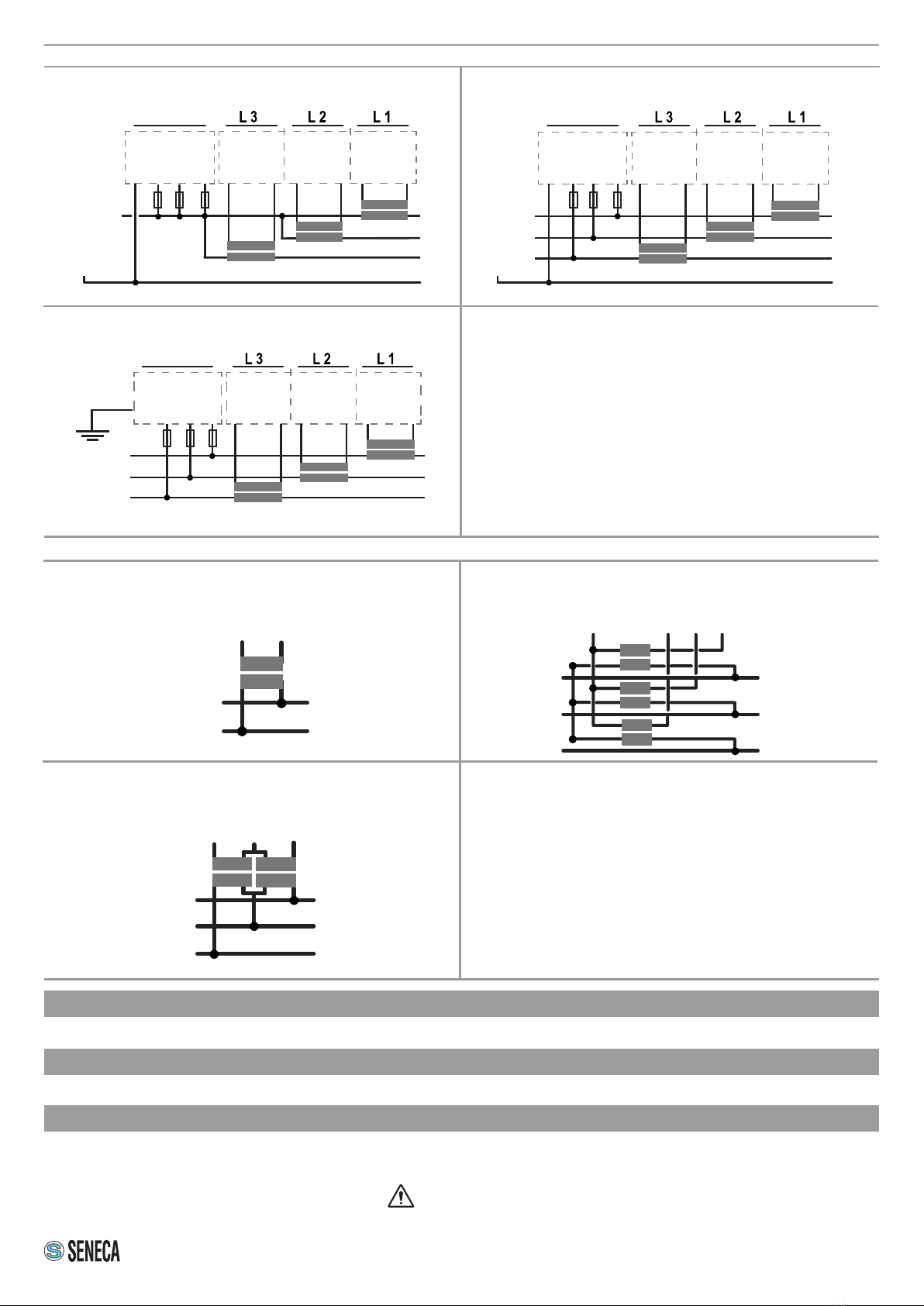
MEASUREMENT
INPUTS
Voltage up to 600 Vac, frequency 45 ÷ 65 Hz
Current
Input
Current input for CT: 1 ÷ 5 Full scale.
voltage input (mV) for CT with voltage output or Rogowski: up to 333 mV full scale.
Base prec.
(*)
Network frequency: 50 ÷ 60 Hz. Voltmeter: 0.2 %
Ammeter: 0.2%, wattmeter: 0.5%
(*) See the user manual for the error limits.
WARNING: The full content of this manual must be read before any operation. The module must only be used by
qualied electricians. Specic documentation is available via QR-CODE shown on page 1.
Electrical and electronic waste disposal (applicable in the European Union and other countries with recycling).
The symbol on the product or its packaging shows the product must be surrendered to a collection centre
authorized to recycle electrical and electronic waste.
The module must be repaired and damaged parts replaced by the Manufacturer. The product is sensitive to
electrostatic discharges. Take appropriate measures during any operation.
PRELIMINARY WARNINGS
The word WARNING preceded by the symbol indicates conditions or actions that put the user's safety at risk.
The word ATTENTION preceded by the symbol indicates conditions or actions that might damage the
instrument or the connected equipment. The warranty shall become null and void in the event of improper use or
tampering with the module or devices supplied by the manufacturer as necessary for its correct operation, and if
the instructions contained in this manual are not followed.
ETH1
LAN
ETH2
WAN
PWR USB
RS485
DIGITAL
I/O
ANALOG
INPUT
ANALOG
OUTPUT
* (Rated withstand voltage)