Electro motive EMD 645 User manual

NAVAL
FACILITIES
ENGINEERING
SERVICE
CENTER
Port
Hueneme,
California
93043-4370
USER
GUIDE
UG-2022-ENV
USER
GUIDE
FOR
CONVERSION
TO
DUAL
FUEL
OPERATION
OF
EMD
645
ENGINES
ON
NAVY
MUSE
GENERATOR
SETS
by
Norman
L.
Helgeson,
Ph.D.
Scott
E.
Jensen,
Eugene
Conversions,
Inc.
Allen
E.
Willey,
POl
Delbert
Terrell,
P02
Dave
Vawter,
POl
Michael
Childers,
POl
March
1997
Sponsored
by
Naval
Facilities
Engineering
Command
19970825
130
DTIG
QUALITY
INSPECTED
S
Approved
for
public
release;
distribution
is
unlimited.
^\
Printed
on
recycled
paper

REPORT
DOCUMENTATION
PAGE
Form
Approved
OMB
No.
0704-018
Public
reporting
burden
for
this
collection
of
information
is
estimated
to
average
1
hour
per
response,
including
the
time
for
reviewing
instructions,
searching
existing
data
sources,
gathering
and
maintaining
the
data
needed,
and
completing
and
reviewing
the
collection
of
information.
Send
comments
regarding
this
burden
estimate
or
any
other
aspect
of
this
collection
information,
including
suggestions
for
reducing
this
burden,
to
Washington
Headquarters
Services,
Directorate
for
Information
and
Reports,
1215
Jefferson
Davis
Highway,
Suite
1204,
Arlington,
VA
22202-4302,
and
to
the
Office
of
Management
and
Budget,
Paperwork
Reduction
Project
(0704-0188),
Washington,
DC
20503.
1.
AGENCY
USE
ONLY
(Leave
blank)
2.
REPORT
DATE
March
1997
3.
REPORT
TYPE
AND
DATES
COVERED
Final
4.
TITLE
AND
SUBTITLE
USER
GUIDE
FOR
CONVERSION
TO
DUAL
FUEL
OPERATION
OF
EMD
645
ENGINES
ON
NAVY
MUSE
GENERATOR
SETS
5.
FUNDING
NUMBERS
6.
AUTHOR(S)
N.L.
Helgeson,
Ph.D,
S.E.
Jenson
(Eugene
Conversions,
Inc.),
A.
Wiley,
D.
Terrell,
D.
Vawter,
and
M.
Childers
7.
PERFORMING
ORGANIZATION
NAME(S)
AND
ADDRESSE(S)
Naval
Facilities
Engineering
Service
Center
1100
23rd
Ave
Port
Hueneme,CA
93043-4370
8.
PERFORMING
ORGANIZATION
REPORT
NUMBER
UG-2022-ENV
9.
SPONSORING/MONITORING
AGENCY
NAME(S)
AND
ADDRESSES
Naval
Facilities
Engineering
Command
Chief
of
Naval
Operations
200
Stovall
Street
2000
Navy
Pentagon
(Code
N45)
Alexandria,
VA
22332-2300
Washington,
DC
20350-2000
10.
SPONSORING/MONITORING
AGENCY
REPORT
NUMBER
11.
SUPPLEMENTARY
NOTES
12a.
DISTRIBUTION/AVAILABILITY
STATEMENT
Approved
for
public
release;
distribution
is
unlimited.
12b.
DISTRIBUTION
CODE
13.
ABSTRACT
(Maximum
200
words)
Conrversion
of
the
Navy's
Mobile
Utilities
System
Equipment
(MUSE)
diesel
generators
to
dual
fuel
(natural
gas
plus
diesel
fuel)
operation
to
reduce
their
NOx
(nitrogen
oxide)
emissions
is
described.
The
Navy
maintains
a
fleet
of
60
such
units,
powered
by
EMD
645
engines,
that
range
in
size
from
1,500
kW
to
2,500
kW.
A
means
for
providing
low-NOx
MUSE
generators
that
will
not
compromise
the
operational
capability
of
the
fleet
is
required.
This
guide
is
based
upon
the
experience
gained
from
converting
a
1,500
kW
MUSE
unit
to
dual
fuel
operation
(the
unit
is
currently
installed
and
operating
at
King's
Bay
Naval
Station
in
Georgia).
Information
on
the
conversion
process,
operation,
maintenance,
and
the
cost
of
the
dual
fuel
conversion
are
provided.
14.
SUBJECT
TERMS
Diesel
generators,
MUSE,
dual
fuel
conversions,
low-NOx
emissions,
EMD
645
engines,
and
natural
gas
operations.
15.
NUMBER
OF
PAGES
166
16.
PRICE
CODE
17.
SECURITY
CLASSIFICATION
OF
REPORT
I
Unclassified
18.
SECURITY
CLASSIFICATION
OF
THIS
PAGE
Unclassified
19.
SECURITY
CLASSIFICATION
OF
ABSTRACT
Unclassified
20.
LIMITATION
OF
ABSTRACT
UL
NSN
7540-01-280-5500
Standard
Form
298
(Rev.
2-89)
Prescribed
by
ANSI
Std.
239-18

EXECUTIVE
SUMMARY
Steps
are
described
for
converting
the
Navy's
Mobile
Utilities
System
Equipment
(MUSE)
diesel
generators
to
dual
fuel
(natural
gas
plus
diesel
fuel)
operation
to
reduce
their
NOx
(nitrogen
oxide)
emissions.
The
Navy
maintains
a
fleet
of
60
such
units,
powered
by
EMD
645
engines,
that
range
in
size
from
1500
kW
to
2,500
kW.
As
the
current
MUSE
diesel
units
meet
few
existing
local
NOx
emission
regulations,
newer
more-restrictive
regulations
(a
trend
now
ensured
with
the
proposed
further
tightening
of
the
National
Ambient
Air
Quality
Standards)
will
ensure
that
the
areas
accessible
to
MUSE
diesel
generators
will
continue
to
decrease.
Therefore
a
means
for
providing
low-NOx
MUSE
generators
that
will
not
compromise
the
operational
capability
of
the
fleet
is
required.
This
guide
is
based
upon
the
experience
gained
from
converting
to
dual
fuel
operation
a
1500
kW
MUSE
unit
that
is
now
installed
and
operating
at
the
King's
Bay
Naval
Station
in
Georgia.
Information
on
the
conversion
process,
operation,
maintenance
and
the
cost
of
the
dual
fuel
conversion
are
provided.
NOx
emission
reductions
of
70
percent
were
demonstrated
with
this
unit;
NOx
reductions
of
greater
than
90.
per
cent
are
achievable
using
an
additional
secondary
ignition
cell.
Capital
requirements
for
the
retro-fit
dual
fuel
conversion
of
a
2500
kW
MUSE
engine
generator
are
shown
to
be
$158.
per
kilowatt
(including
the
secondary
ignition
cells).
This
is
compared
to
the
cost
of
replacing
this
same
MUSE
unit
with
a
new
spark-ignited,
low-NOx,
natural
gas
engine.
The
cost
for
the
latter
is
$560.
per
kilowat.
For
a
2500
kW
MUSE
unit,
these
numbers
translate
into
a
capital
savings
of
over
$1.0
million
if
the
option
of
retro-fitting
for
dual
fuel
operation
is
chosen.
Operating
costs
for
dual
fuel
(natural
gas)
operation
of
MUSE
generating
sets
are
also
substantially
reduced
over
that
of
unmodified
diesel
operation.
For
the
case
evaluated,
the
cost
for
natural
gas
firing
is
4.1
cents
per
kW-hr
while
that
for
diesel
firing
is
8.9
cents
kW-hr.
A
further
major
operational
(strategic)
advantage
of
the
retro-fit
dual
fuel
unit
over
that
of
a
new,
spark-ignited,
natural
gas
engine
is
that
it
can
be
made
to
operate
as
either
a
full
diesel
or
a
full
natural
gas
unit.
DTIC
QUALFiT
ESBPi30'.i.'iSD
3
in
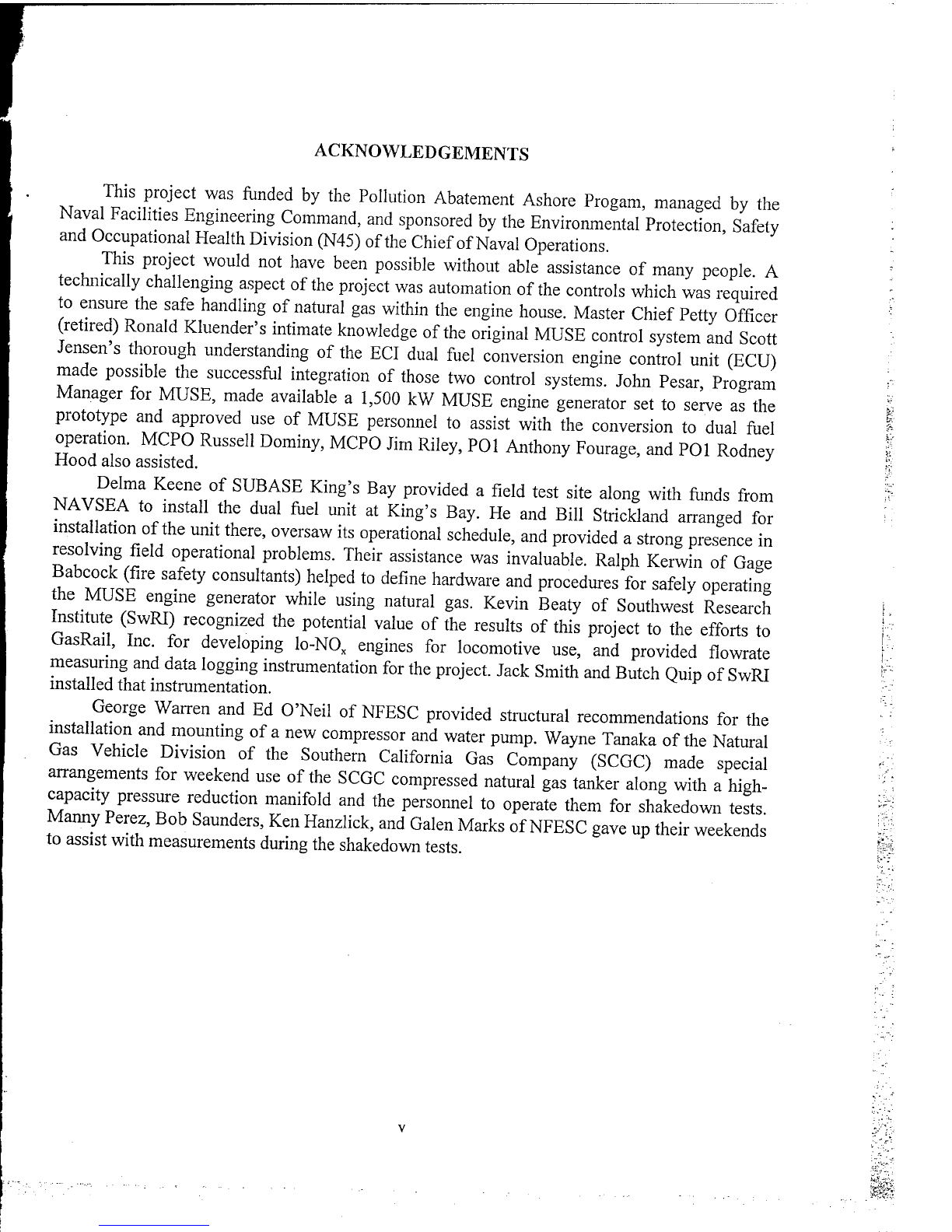
ACKNOWLEDGEMENTS
XT
,?
S
.
?
r0jeCt
WaS
fonded
by
the
Pollution
Abatement
Ashore
Progam,
managed
by
the
Naval
Facilities
Engineering
Command,
and
sponsored
by
the
Environmental
Protection
Safety
and
Occupational
Health
Division
(N45)
of
the
Chief
of
Naval
Operations.
This
project
would
not
have
been
possible
without
able
assistance
of
many
people
A
technically
challenging
aspect
of
the
project
was
automation
of
the
controls
which
was
required
to
ensure
the
safe
handling
of
natural
gas
within
the
engine
house.
Master
Chief
Petty
Officer
(retired)
Ronald
Kluender's
intimate
knowledge
of
the
original
MUSE
control
system
and
Scott
Jensen
s
thorough
understanding
of
the
ECI
dual
fuel
conversion
engine
control
unit
(ECU)
made
possible
the
successful
integration
of
those
two
control
systems.
John
Pesar
Program
Manager
for
MUSE,
made
available
a
1,500
kW
MUSE
engine
generator
set
to
serve
as
the
prototype
and
approved
use
of
MUSE
personnel
to
assist
with
the
conversion
to
dual
fuel
operation.
MCPO
Russell
Dominy,
MCPO
Jim
Riley,
POl
Anthony
Fourage,
and
POl
Rodney
Hood
also
assisted.
J
WAVS??
Keene
n
0
f
L
S
UBASE
Kin
§'
s
Ba
y
P
rovi
ded
a
field
test
site
along
with
funds
from
NAVSEA
to
install
the
dual
fuel
unit
at
King's
Bay.
He
and
Bill
Strickland
arranged
for
installation
of
the
unit
there,
oversaw
its
operational
schedule,
and
provided
a
strong
presence
in
resolving
field
operational
problems.
Their
assistance
was
invaluable.
Ralph
Kerwin
of
Gage
£
A°^C?
Safety
COnsuItants
)
heI
P
ed
t0
defi
"e
hardware
and
procedures
for
safely
operating
he
MUSE
engine
generator
while
using
natural
gas.
Kevin
Beaty
of
Southwest
Research
Institute
(SwRI)
recognized
the
potential
value
of
the
results
of
this
project
to
the
efforts
to
GasRail,
Inc
for
developing
lo-NO
x
engines
for
locomotive
use,
and
provided
flowrate
measuring
and
data
logging
instrumentation
for
the
project.
Jack
Smith
and
Butch
Quip
of
SwRI
installed
that
instrumentation.
_
George
Warren
and
Ed
O'Neil
of
NFESC
provided
structural
recommendations
for
the
installation
and
mounting
of
a
new
compressor
and
water
pump.
Wayne
Tanaka
of
the
Natural
Gas
Vehicle
Division
of
the
Southern
California
Gas
Company
(SCGC)
made
special
arrangements
for
weekend
use
of
the
SCGC
compressed
natural
gas
tanker
along
with
a
high-
capacity
pressure
reduction
manifold
and
the
personnel
to
operate
them
for
shakedown
tests
Manny
Perez,
Bob
Saunders,
Ken
Hanzlick,
and
Galen
Marks
of
NFESC
gave
up
their
weekends
to
assist
with
measurements
during
the
shakedown
tests.
pS

CONTENTS
Page
1.0
INTRODUCTION
1-1
1.1
Environmental
Compliance
and
Navy
Need
1-1
1.2
Selection
of
NO
x
Control
Technology
1-2
1.3
Installation
and
Testing
of
Prototype
Dual-Fuel
MUSE
Diesel
Generator
1-2
1.4
Organization
of
the
Guide
1-3
2.0
NO
x
REDUCTION
FOR
LARGE,
TWO-STROKE
DIESEL
ENGINES
2-1
2.1
Exhaust
Gas
Treatment
2-1
2.2
NO
x
Reduction
From
EMD
645
Dual-Fuel
Engines
2-2
2.3
Further
Rduction
of
NO
x
Emissions
2-3
3.0
ELEMENTS
OF
THE
ECI/EMD
DUAL-FUEL
CONVERSION
3-1
3.1
Natural
Gas
Fuel
3-1
3.2
Dual
Fuel
Characteristics
3-1
3.3
Engine
Operating
Sequence
3-2
3.4
Conversion
Kit
Components
3-3
3.4.1
Duel
Fuel
Heads
and
Pistons
3-3
3.4.2
Gas
Inlet
Valves
3-3
3.4.3
Pilot
Fuel
Control
and
Diesel
Injection
3-3
3.4.4
Low
Emission
Idle
(LEI)
3-4
3.4.5
Electronic
Control
Unit
3-4
4.0
SUB-SYSTEM
DESCRIPTIONS
AND
INSTALLATION
PROCEDURES
4-1
4.1
Engine
Modifications
4-1
4.1.1
Power
Pack
Assembly
4-1
4.1.2
Cylinder
Relief
Valves
4-1
4.1.3
Diesel
Fuel
Supply
4-1
4.2
Natural
Gas
Supply
System
4-2
4.3
Control
Air
System
4-2
Vll
CONTENTS
Page
4.4
Air
Throttle
4
"
3
4.5
Engine
Cooling
System
4
"
3
4.6
Sensors
4
"
4
4.6.1
Thermocouples
4
"
4
4.6.2
Water
Temperature
4
~
4
4.6.3
Control
Air
Pressure
4
"
4
4.6.4
Flywheel
Sensors
4
"
4
4.6.5
Air
Box
Temperature
4
~
4
4.6.6
Air
Box
Pressure
4
"
4
4.6.7
Natural
Gas
Sensors
4-4
4.6.8
Gas
Header
Pressure
4
"
4
4.7
Natural
Gas
Safety
System
4
"
5
4.8
Electrical
System
and
Controls
4_5
4.8.1
Engine
Control
Unit
4
"
6
4.8.2
Air
Service
Cabinet
and
Engine
Control
Panel
4-6
4.8.3
GIV
Wire
Harness
4
"
6
4.9
Switchgear,
External
Power
Hookups
and
External
Communications
4-6
4.10
Modification
of
MUSE
Schematic
Drawings
4-7
5.0
OPERATIONAL
PROCEDURES
5"
1
5.1
Diesel
Only
Operation
5-1
5.2
Natural
Gas
(Dual
Fuel)
Operation
5_1
5.3
Automatic
Control
5
"
2
5.3.1
Autostart
Software
5-2
5.3.2
ECU
Alarm
Logic
5
"
4
5.3.3.
ECU
Status
Messages
5_4
5.4
The
ECU
•
5_6
5.4.1
ECU
Status
Screen
5_6
5.4.2
Computer
Interface
5
"
6
5.4.3
Using
LCD
Screen
Editor
5
"
6
5.4.4
ECU
Dial-Up
Software
5
"
7
5.4.5
Static
Protection
Precautions
•••
••
5_7
Vlll

CONTENTS
Page
6.0
FIELD
SITE
INSTALLATION,
MAINTENANCE
AND
TRAINING
6-1
6.1
Site
Requirements
"
-1
6.2
Maintenance
Schedule
and
Procedures
6_1
6.3
Training
6_1
7.0
CAPITAL
AND
OPERATING
COSTS
7-1
8.0
REFERENCES
8_1
9.0
GLOSSARY
9_1
APPENDICES
A
-
Letter
Report
Regarding
Fire
Safety
Measures
for
Conversion
of
USN
MUSE
Diesel-Generator
Units
From
Diesel
to
Natural
Gas
Fueling
A-l
B
-
Schematic
Drawings
of
Dual
Fuel
1,500
kW
Conversion
of
Diesel
Power
Plants
B_1
C
-
Maintenance
Bulletins
and
Instructions
c_1
IX
1.0
INTRODUCTION
This
user
data
package
describes
steps
in
the
conversion
of
the
Navy's
Mobile
Utilities
System
Equipment
(MUSE)
transportable
diesel
generator
sets
from
diesel
to
dual
fuel
(natural
gas
plus
diesel
fuel)
operation.
These
diesel
generator
sets
are
part
of
a
fleet
of
60
such
units
maintained
by
the
Navy's
MUSE
detachment
for
deployment
to
Navy,
other
military,
and
sometimes
civilian
uses
throughout
the
world
(Ref
1-1).
The
units
range
in
size
from
750
to
2,500
kW
and
are
powered,
largely,
by
EMD
645
engines
manufactured
by
the
ElectroMotive
Division
of
the
General
Motors
Corporation.
The
engines
are
medium-speed
(750
or
900
RPM),
have
8
to
20
cylinders
with
cylinder
displacements
of
645
cubic
inches,
and
use
a
2-stroke
operational
cycle.
This
guide
is
based
on
the
experience
gained
from
converting
to
dual
fuel
operation
a
1,500-kW
MUSE
unit
that
is
now
installed
and
operating
at
the
King's
Bay
Naval
Station
in
Georgia
(Fig.
1-1).
The
technology
used
for
this
conversion
was
provided
by
ECI
Inc.,
Tacoma,
Washington.
MUSE
personnel,
assisted
by
ECI
technicians,
installed
the
required
engine
modification
hardware
and
the
electrical
and
engine
skid
modifications.
1.1
Environmental
Compliance
and
Navy
Need
Of
the
Navy's
many
diesel
engines,
those
installed
in
its
MUSE
generating
equipment
for
temporary
(<4
years)
stationary
electrical
power
were
the
first
off-road
Navy
engines
to
be
affected
by
environmentally-mandated
nitrogen
oxide
(NO
x
)
emission
regulations.
As
MUSE
units
are
transportable
but
are
typically
employed
at
a
given
site
for
periods
exceeding
that
normally
used
to
define
'temporary
power'
(temporary
power
is
often
defined
as
service
not
exceeding
one
year),
they
must
comply
with
air
pollution
regulations
that
apply
to
stationary
power
generating
equipment.
But
regulatory
emission
standards
for
stationary
power
units
are
highly
variable
as
they
both
depend
upon
the
degree
of
nonattainment
in
the
surrounding
air
control
region
and
upon
the
air
control
district
in
which
the
region
is
located.
Therefore
MUSE
units
must
have
a
capability
for
meeting
these
variable
standards
as
the
units
are
moved
from
one
location
to
another.
Such
regulations
can
vary
from
none
to
those
applicable
in
the
South
Coast
Air
Quality
Management
District
(SCAQMD)
of
California,
where
emission
limits
are
<
1.0
gram/horsepower-hour
(gm/HpH).
As
NO
x
emissions
from
current
MUSE
units
range
anywhere
from
12
to
16
gm/HpH,
attempts
to
operate
them
in
areas
in
which
they
do
not
comply
with
emission
regulations
could
result
in
the
imposition
of
heavy
fines
and
as
well
as
ordered
shut-
down
by
civilian
authorities.
Therefore
a
means
for
reducing
NO
x
emissions
from
them
is
required.
The
following
factors
and
criteria
were
determined
to
be
important
in
evaluating
approaches
for
reducing
NO
x
emissions
from
MUSE
diesel
generator
sets:
(a)
most
MUSE
engine
generator
units
are
driven
by
an
EMD
645
engine,
(b)
when
burning
diesel
fuel,
these
EMD
engines
do
not
meet
the
emission
requirements
in
many
areas
of
the
country
where
the
Navy
operates,
(c)
although
transportable,
MUSE
units
must
comply
with
emission
regulations
that
apply
to
stationary
devices
because
of
their
extended
time
on
site,
(d)the
required
transportability
of
the
MUSE
units
limits
the
types
of
NO
x
emission
control
technology
that
can
1-1
be
used
with
them,
(e)
the
large
number
of
MUSE
units
in
inventory
and
the
cost
of
then-
replacement
requires
that
a
retrofit
rather
than
a
replacement
technology
be
acquired
for
reducing
NO
x
emissions,
(f)
a
capability
for
firing
diesel
fuel
must
be
maintained
to
meet
the
Navy's
operational
commitments,
(g)
full
generator
power
capability
must
be
maintained,
(h)
reliability
equal
to
or
better
than
that
for
the
diesel-only
configuration
is
needed,
(i)
the
technology
selected
must
be
within
the
technical
expertise
of
MUSE
and
onsite
personnel
who
will
be
required
to
operate
and
maintain
the
modified
units,
and
(j)
operational
costs
must
not
escalate
appreciably
beyond
those
incurred
when
the
MUSE
unit
is
operating
as
a
diesel-only
engine.
1.2
Selection
of
NO
x
Control
Technology
Two
general
approaches
can
be
used
for
reducing
NO
x
emissions
from
diesel
engines:
(a)
modification
of
the
engine
combustion
process
so
that
fewer
NO
x
species
(nitric
oxide,
NO,
and
nitrogen
dioxide,
N0
2
)
are
generated,
and/or
(b)
treatment
of
the
exhaust
gases
to
destroy
the
NO
x
species
generated
to
prevent
their
emission
into
the
atmosphere.
Of
the
many
variations
of
these
approaches
that
have
been
investigated,
two
were
considered
for
application
to
MUSE
diesel
generator
sets:
(a)
conversion
of
the
engine
to
dual
fuel
operation,
and
(b)
the
use
of
selective
catalytic
reduction
(SCR)
for
treatment
of
the
engine
exhaust
stream.
Although
SCR
offers
the
advantage
of
bringing
the
MUSE
engine
generators
into
immediate
full
compliance
with
the
most
restrictive
of
NO
x
emission
regulations,
its
application
would
add
significant
cost,
complexity,
and
size
(requiring
that
an
additional
module
be
transported)
to
the
transportable
MUSE
engine
generator
set,
and
would
also
introduce
ammonia
(NH3,
a
hazardous
chemical)
at
the
operating
site.
NH3,
which
is
used
as
the
chemical
reductant
for
NO
x
,
is
not
only
a
hazardous
chemical,
but,
itself,
presents
a
threat
to
the
environment.
Therefore
the
SCR
process
using
NH3
as
the
reductant
was
not
considered
to
be
a
practical
solution
for
reducing
NO
x
emissions
from
MUSE
diesel
generator
sets.
The
recommended
application
of
dual-fuel
technology
(or
alternative
fuel)
is
based
upon
a
retrofit
conversion
kit
designed,
specifically,
for
the
EMD
645
engine
by
Energy
Conversions,
Incorporated,
Tacoma,
WA.
The
performance,
reliability,
and
emissions
reduction
of
that
conversion
technology
have
been
demonstrated
in
a
single
application
on
two
tandem
locomotives
used
for
coal
line-haul
operations
on
the
Burlington
and
Northern
Railway
between
Montana
and
Wisconsin
(Ref
1-2).
Liquefied
natural
gas
(LNG)
from
a
separate
LNG
fuel
car
was
used
to
fuel
the
tandem
locomotives,
and
NO
x
reductions
of
nearly
70
percent
(to
4.0
from
the
12.0
gms./Hph
produced
when
burning
diesel
fuel)
were
achieved.
Because
of
these
demonstrated
results,
because
no
other
competing
technology
could
make
similar
claims
with
the
EMD
645
engine,
and
because
this
technology
satisfied
the
criteria
for
selection
of
a
MUSE
NO
x
reduction
technology
(discussed
above),
it
was
selected
for
installation
and
testing
on
a
1,500
kW
MUSE
diesel
generator
set.
1.3
Installation
and
Testing
of
Prototype
Dual
Fuel
MUSE
Diesel
Generator
The
retrofit,
dual
fuel
conversion
was
completed
in
July
1995
at
the
Construction
Battalion
Center
in
Port
Hueneme,
California.
Although
previously
tested
in
a
locomotive
application,
it
had
not
been
used
for
stationary
power.
And
although
the
application
to
stationary
power
is,
in
ways,
not
as
complex
as
that
for
locomotives,
it
is
different
and
presents
other
1-2
significant
challenges.
To
meet
these
new
challenges,
to
accommodate
the
use
of
natural
gas
within
the
MUSE
unit,
and
to
provide
a
capability
for
the
remote
operation
of
the
engine
generator
unit,
a
new
automated
control
system
was
designed
and
installed
along
with
the
dual-
fuel
conversion.
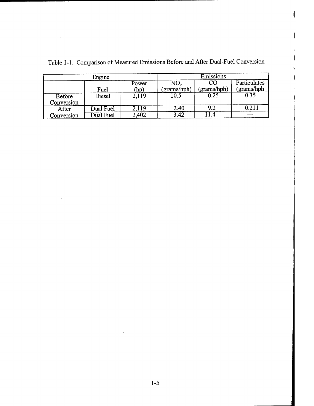
Operational
checkout
tests
of
the
modified
unit
provided
the
emissions
data
that
are
summarized
in
Table
1-1.
The
tests
also
showed:
(a)
that
the
unit
could
be
started,
electrically
synchronized
with
a
grid,
stopped,
and
otherwise
controlled
remotely,
(b)
that
full
engine
generator
set
power
could
be
produced,
and
(c)
that
NO
x
emissions
could
be
reduced
by
65
percent,
the
approximate
level
anticipated
by
the
dual
fuel
conversion.
The
modified
unit
was
then
transported
to
SUBASE
King's
Bay
Georgia
where
it
is
now
undergoing
field
testing.
Further
engine
efficiency,
fuel
usage,
power,
and
emissions
data
will
be
obtained
during
the
field
test
period
along
with
maintenance
and
other
operational
and
control
data.
1.4
Organization
of
the
Guide
This
guide
contains
the
information
necessary
for
installing,
operating,
and
maintaining
the
dual
fuel
conversion
hardware
supplied
by
ECI
Inc.,
Tacoma
WA,
when
used
on
MUSE
diesel
generator
units
that
utilize
the
EMD
645
engine.
Section
2
reviews
some
of
the
factors
involved
in
NO
x
production
in
2-stroke
diesel
engines
and
some
of
the
efforts
that
have
been
undertaken
previously
to
minimize
those
emissions.
Suggestions
are
included
for
making
further
important
reductions
in
NO
x
emissions
from
the
EMD
645
engines.
Section
3
describes
the
fundamental
elements
of
the
ECI
dual
fuel
conversion
kit,
and
Section
4
provides
detailed
descriptions
and
installation
instructions
for
the
conversion
sub-systems,
as
defined
for
this
new
application.
Section
5
describes
operational
procedures
of
the
converted
unit
and
Section
6
discusses
field
site
installation,
maintenance,
and
training
requirements.
Section
7
provides
capital
and
operating
costs
for
the
retrofit,
dual-fuel
MUSE
diesel
generator.
1-3

(a)
Side
view
of
switchgear,
interconnecting
cable
housing,
and
engine
house.
IM*fc*fci&i
(b)
End
view
showing
natural
gas
supply
line.
Figure
1-1.
MUSE
1,500
kW
dual-fuel
engine
generating
set
at
SUBASE,
King's
Bay,
Georgia.
1-4
Table
1-1.
Comparison
of
Measured
Emissions
Before
and
After
Dual-Fuel
Conversion
Engine
Emissions
Fuel
Power
(hp)
NO
x
(grams/hph)
CO
(grams/hph)
Particulates
(grams/hph
Before
Conversion
Diesel
2,119
10.5
0.25
0.35
After
Conversion
Dual
Fuel
2,119
2.40
9.2
0.211
Dual
Fuel
2,402
3.42
11.4
—
1-5

2.0
NO
x
REDUCTION
FOR
LARGE,
TWO-STROKE
DIESEL
ENGINES
Of
the
many
combustion
devices
having
large
commercial
usage,
diesel
engines
have
provided
the
greatest
technical
challenges
to
achieving
significant
NO
x
reductions.
Two
general
approaches
can
be
used
to
reduce
NO
x
emissions
from
them:
(a)
modification
of
the
engine
combustion
process
so
that
fewer
NO
x
species
(nitric
oxide,
NO,
and
nitrogen
dioxide,
N0
2
)
are
generated,
and/or
(b)
treatment
of
the
exhaust
gases
to
destroy
the
NO
x
species
generated
and
to
prevent
their
emission
into
the
atmosphere.
As
diesel
engines
are
lean-burn
(stoichiometrically,
fuel
lean),
the
catalytic
reactors
used
by
spark-ignited
gasoline
engines
to
reduce
NO
x
and
hydrocarbon
emissions
and
which
require
near-stoichiometric
combustion,
are
not
effective
for
reducing
the
concentrations
of
the
same
pollutant
species
from
diesel
exhausts.
Further,
diesel
engines
operate
at
higher
compression
ratios
than
gasoline
engines
and
combustion
in
them
proceeds
according
to
a
complex,
heterogeneous
diffusion
process
as
opposed
to
the
simpler,
easier-to-control,
homogeneous
flame
propogation
that
characterizes
gasoline
engine
combustion
(see
Fig.
2-1).
The
higher
compression
ratio
of
the
diesel
engine
leads
to
its
greater
efficiency
and
the
diffusion-controlled
combustion
is
what
permits
its
operation
at
higher
pressures
without
the
occurrence
of
destructive
knocking.
However,
both
of
these
factors
lead
to
higher
combustion
temperatures
and
increased
NO
x
production
in
the
diesel
engine.
Most
of
the
work
for
reducing
NO
x
emissions
from
diesel
engines
has
been
with
smaller
sized
engines.
Little
research
has
been
carried
out
on
engines
as
large
as
the
EMD
645.
And
as
the
complexity
of
combustion
increases
and
one's
ability
to
control
those
processes
decreases
with
engine
size,
progress
in
NO
x
emissions
reduction
from
larger
engines
has
been
comparably
slow.
However,
as
characterization
of
the
fundamental
processes
in
diesel
engines
improves,
the
results
for
controlling
NO
x
emissions
from
both
large
and
small
engines
may
improve.
The
Navy's
Office
of
Naval
Research
(ONR)
is
sponsoring
fundamental
research
(see
Refs
2-1,
2-2,
and
2-3)
on
the
control
of
NO
x
emissions
from
the
larger
engines
used
for
boat
and
ship
operations.
Those
results
could
also
find
an
application
with
MUSE
engines.
However,
the
practical
application
of
that
research,
if
successful,
is
several
years
in
the
future.
A
further
complication
with
the
EMD
645
engines
is
that
they
are
2-stroke
engines.
This
reduces
the
number
of
engine
parameters
available
for
controlling
or
altering
the
internal
engine
processes
for
the
purpose
of
NO
x
reduction.
Further,
most
work
on
NO
x
reduction
from
diesel
engines
has
been
on
those
of
the
4-stroke
design.
Therefore,
the
quantity
of
engine
research
to
draw
on
for
reducing
NO
x
emissions
from
the
EMD
645
engine
is
limited.
2.1
Exhaust
Gas
Treatment
Exhaust
gas
treatment
provides
one
option
for
significantly
reducing
NO
x
emissions
from
diesel
engines,
although
the
additional
equipment
and
chemicals
required
for
its
implementation
works
against
its
application
on
MUSE
units.
Two
such
approaches
are
available
commercially;
others
are
being
developed.
Those
available
commercially
use
a
chemical
reductant
either
with
catalysts
(selective
catalytic
reduction
(SCR)),
or
without
catalysts
(selective
non-catalytic
reduction
(SNCR)).
The
reductants
used
are
usually
ammonia
or
a
related
compound
such
as
2-1

urea.
Other
than
the
identification
of
a
useful
chemical
additive,
the
development
of
an
appropriate
catalyst
is
the
major
technical
problem
in
the
development
of
a
useful
SCR
approach.
Although
SNCR
requires
no
catalyst,
other
chemical
routes
and
temperatures
for
the
destruction
of
NO
x
must
be
used.
The
general
features
and
flow
paths
of
the
two
approaches
are
contrasted
in
Figure
2-1.
Ammonia
has
been
the
chemical
most
used
for
NO
x
reduction,
but
recent
years
have
seen
development
of
the
use
of
related
chemicals
(e.g.,
urea
and
cyanuric
acid).
Ammonia
and
urea
have
both
been
used
in
SNCR
and
SCR
processes,
but
the
temperature
window
of
their
application
for
SNCR
is
too
high
to
be
useful
with
diesel
exhausts.
The
use
of
urea
in
SCR
processes
is
a
rather
recent
development
and
offers
significant
advantages
over
that
of
ammonia.
SCR
(urea)
provides
at
least
the
NO
x
reduction
that
SCR
(NH
3
)
provides
(both
>90
percent),
but
without
the
burden
of
being
either
a
hazardous
chemical
or
an
environmental
threat.
The
use
of
SCR
(urea)
was
developed
in
Europe
and
is
currently
available
only
from
European
suppliers.
Cyanuric
acid
has
been
used
for
SNCR
(non-catalytic)
processes.
Its
major
claim
is
that
it
is
more
effective
than
either
ammonia
or
urea
at
the
lower
temperatures
characteristic
of
diesel
exhausts.
2.2
NO
x
Reduction
From
EMD
645
Dual-Fuel
Engines
Several
efforts
have
been
undertaken
to
use
natural
gas
with
2-stroke
diesel
engines.
Those
of
interest
to
the
MUSE
engine
generator
program
are
summarized
in
Table
2-1.
The
first
line
provides
operating
data
from
current
MUSE
EMD
645
diesel
engines
as
a
baseline
for
comparison.
The
remaining
cases
are
for
engines
from
the
same
locomotive-type
engine
series
(the
EMD's
567,
645,
and
710,
cylinder
displacement
in
cubic
inches)
and
the
Detroit
Diesel
92
(a
truck-sized
engine).
Fuel
type
is
either
dual
fuel
(DF)
or
natural
gas
(NG),
and
charging
of
the
engine
cylinders
with
natural
gas
is
described
as
either
early
or
late
in
the
compression
stroke.
For
early
injection
(El),
a
low
injection
pressure
(100
to
300
psi)
can
be
used.
Air
flow
and
mixing
patterns
within
the
cylinder
then
produce
a
nearly
homogeneous
fuel/air
mixture
prior
to
ignition.
For
late
cycle
injection
(LCI),
a
much
higher
pressure
(>3,000
psi)
is
required,
and
as
pre-mixing
of
the
fuel
and
air
is
not
achieved
prior
to
ignition,
a
diesel-type
combustion
takes
place.
Ignition
of
the
natural
gas
charge
in
both
of
these
cases
is
by
injection
of
a
pilot
quantity
of
diesel
fuel
(4
to
7
percent
of
the
amount
required
for
full
diesel
operation)
into
the
cylinder
at
the
time
of
ignition.
Significant
NO
x
reduction
is
achieved
with
the
El
process.
NO
x
reduction
is
much
more
difficult
to
achieve
for
the
LCI
process.
Anticipated
advantages
of
LCI
are
increased
engine
thermal
efficiency
(a
higher
compression
ratio
diesel
cycle
can
be
used)
and
avoidance
of
the
combustion
"knock"
that
limits
power
production
in
Otto
cycle
(homogeneous
combustion)
engines.
Disadvantages
of
LCI
are
the
technical
problems
and
high
cost
of
providing
natural
gas
at
pressures
greater
than
3,000
psi
and
the
difficulty
in
achieving
reduced
NO
x
emissions
in
higher-pressure,
higher-temperature
combustion
environments.
The
advantage
of
reduced
fuel
costs
due
to
the
use
of
natural
gas
rather
than
diesel
fuel
is
provided
by
both
approaches.
The
data
of
Case
1
were
obtained
in
1982
from
a
locomotive
engine
fueled
from
compressed
natural
gas
cylinders
carried
on
a
railroad
flatcar
(Ref
2-4).
The
major
limitation
observed
in
that
test
operation
was
the
reduction
(20
to
30
percent)
of
available
engine
power
2-2
caused
by
the
onset
of
combustion
knocking.
In
Case
2,
the
Department
of
Energy
(DOE)
sponsored
single-cylinder
engine
tests
(Refs
2-5
and
2-6)
to
determine
if
improved
engine
thermal
efficiencies
and
power
production
could
be
obtained
with
a
diesel-type
(late
cycle
injection)
combustion
process
for
dual
fuel
operation.
Although
substantial
progress
was
made
in
these
tests,
engine
efficiency
and
exhaust
emission
objectives
were
not
achieved.
The
DD
92
spark-ignited,
truck-sized
engine
(Case
3)
had
significantly
different
requirements
than
those
for
the
larger
locomotive
engines.
Its
manufacture
was
discontinued
after
several
years'
production.
Case
4
was
undertaken
by
many
of
the
same
parties
involved
in
Case
1,
but
with
several
changes.
These
included:
using
turbocharging
rather
than
positive
displacement
compressors
for
charge-air
compression;
changing
the
piston
crown
design
to
improve
fuel-air
mixing
and
to
reduce
the
compression
from
14.5
to
12.8;
altering
the
head
configuration
to
allow
admission
of
natural
gas
into
the
chamber
using
electronic
rather
than
mechanical
controls;
incorporating
additional
charge-air
cooling
for
the
engine;
modifying
the
controls
of
the
injector
rack;
and
incorporating
single-bank
engine
idling
to
reduce
emissions
and
improve
engine
efficiency
(Ref
2-7).
The
results
achieved
were
sufficient
to
convince
the
Burlington
and
Northern
Railway
to
install
retro-fit
packages
designed,
specifically,
for
the
EMD
645
engine
on
two
tandem
locomotives
for
coal
line-haul
operations
between
Montana
and
Wisconsin.
Liquefied
natural
gas
(LNG)
was
used
as
the
fuel,
and
a
separate
LNG
fuel
car
was
constructed
to
provide
fuel.
An
LNG
refueling
station
for
the
round
trip
was
provided
in
Minnesota.
The
performance,
reliability,
and
emissions
reduction
of
that
technology
were
demonstrated
in
a
program
that
continued
for
over
two
years.
The
technology
represented
by
this
demonstration
test
appears
to
be
the
only
engine-related
retro-fit
technology
available
for
achieving
significant
NO
x
reductions
with
the
EMD
645
engine.
The
last
entry
in
Table
2-1
is
for
development
tests
that
have
been
underway
at
the
Southwest
Research
Institute
(SwRI)
for
development
of
the
late,
high-pressure
injection
of
natural
gas.
Data
regarding
the
performance,
emissions,
cost,
and
reliability
of
this
technology
have
not
yet
been
published.
2.3
Further
Reduction
of
NO
x
Emissions
Although
the
70
percent
reduction
in
NO
x
demonstrated
by
the
results
of
Case
4
is
an
important
step
forward,
further
NO
x
reductions
appear
to
be
available
with
some
additional
modification
of
the
dual-fuel
EMD
645
engine.
These
have
centered
on
the
use
of
pre-ignition
chambers
and/or
separate
diesel
injection
igniters
(see
Table
2-2).
The
results
presented
in
this
table
show
that
NO
x
emissions
for
dual
fuel
injection
can
be
reduced
to
the
level
of
1.0
gram/hph
while
the
required
pilot
fuel
is
reduced
to
about
1.0
percent
(Reference
2-8
and
2-9
indicate
that
CO,
hydrocarbon,
and
particular
emission
are
also
significantly
reduced.).
Although
the
use
of
pre-chambers
in
engines
is
a
familiar
concept,
their
use
with
dual
fuel
engines
has
been
limited
and
their
significant
advantages
have
not
been
widely
explored.
In
the
cases
shown,
the
Wartsilla
is
a
somewhat
complex
multi-fueled
application
requiring
high
pressure
injection
(Ref
2-10).
It
would
not
be
useful
for
Navy
MUSE
units.
Cooper
Bessemer
(Cases
2
through
5)
conducted
tests
that
started
with
the
objective
of
improving
the
operation
of
large
spark-ignited
natural
gas
engines
and
resulted
in
major
improvements
in
their
dual
fuel
engines
as
well
(see
Fig.
2-2,
Ref
2-8).
The
Cooper
Bessemer
engines
were
all
four-stroke
units.
Fairbanks-Morse
(Ref
2-9)
achieved
results
similar
to
those
of
Cooper
Bessemer
with
a
900-rpm,
two-stroke,
2-3
opposed-piston
engine.
A
plan
view
of
the
injector
arrangement
for
the
natural
gas,
diesel,
and
pre-chamber
injectors
of
the
Fairbanks
Morse
application
is
shown
on
Fig.
2-3.
When
the
engine
is
operating
in
the
diesel
mode,
both
diesel
injectors
are
used.
In
the
natural
gas
mode,
a
single,
low-pressure
gas
injector
is
used
along
with
a
diesel-fired
pre-ignition
chamber.
Figure
2-4
shows
Fairbanks-Morse
data
for
four
modes
of
engine
operation:
standard
diesel,
standard
dual
fuel,
spark
ignition,
and
Enviro
Design
pre-chamber.
The
numbers
within
each
region
of
the
figure
refer
to
the
number
of
data
points
used
to
define
that
region,
NO
x
emissions
and
thermal
efficiency
(brake-specific
fuel
consumption)
are
significantly
superior
for
the
Enviro-Design.
Pre-chamber
parameters
affecting
the
reliability
and
effectiveness
for
achieving
ignition,
minimum
emissions,
and
minimum
pilot
fuel
are
shown
on
Figure
2-5
(Ref
2-8).
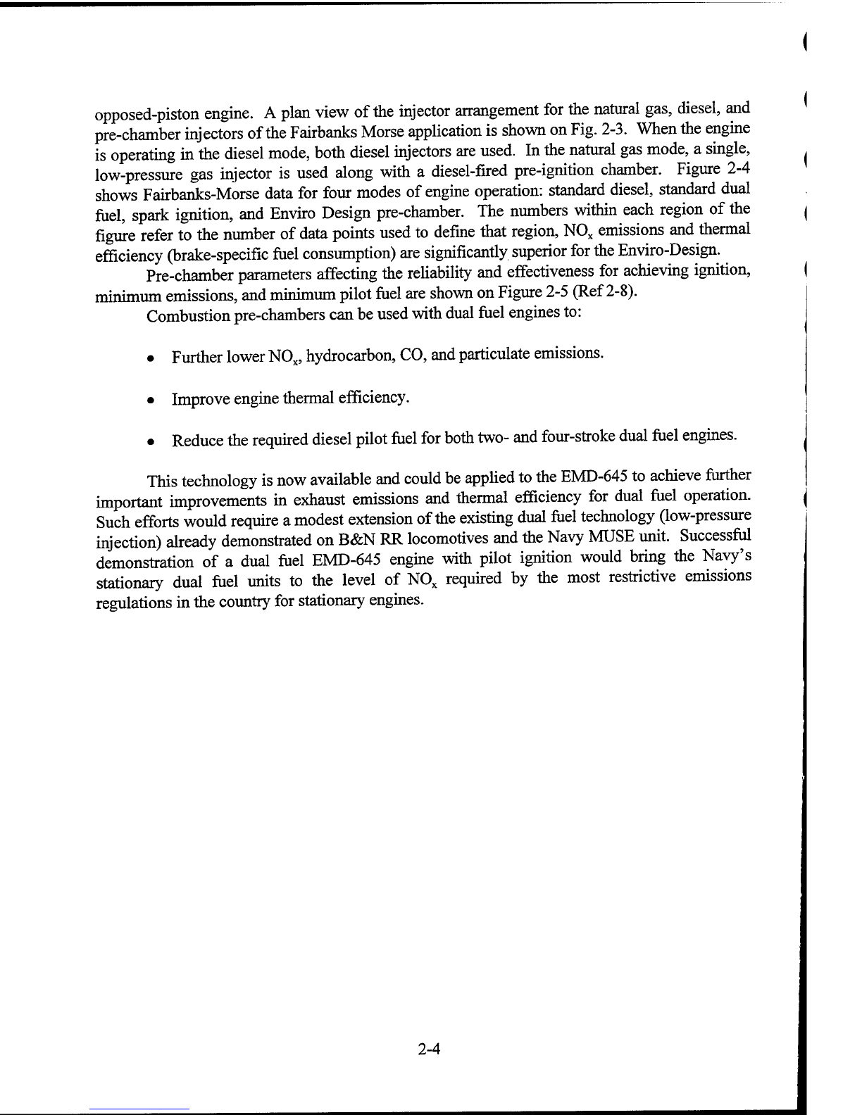
Combustion
pre-chambers
can
be
used
with
dual
fuel
engines
to:
•
Further
lower
NO
x
,
hydrocarbon,
CO,
and
particulate
emissions.
•
Improve
engine
thermal
efficiency.
•
Reduce
the
required
diesel
pilot
fuel
for
both
two-
and
four-stroke
dual
fuel
engines.
This
technology
is
now
available
and
could
be
applied
to
the
EMD-645
to
achieve
further
important
improvements
in
exhaust
emissions
and
thermal
efficiency
for
dual
fuel
operation.
Such
efforts
would
require
a
modest
extension
of
the
existing
dual
fuel
technology
(low-pressure
injection)
already
demonstrated
on
B&N
RR
locomotives
and
the
Navy
MUSE
unit.
Successful
demonstration
of
a
dual
fuel
EMD-645
engine
with
pilot
ignition
would
bring
the
Navy's
stationary
dual
fuel
units
to
the
level
of
NO
x
required
by
the
most
restrictive
emissions
regulations
in
the
country
for
stationary
engines.
2-4

Combustion-
Gases
'.
Heat
Extraction
Heat
Extraction
Exhaust
Gases
1500
-
2000
F
V
NH3
—
Injection
(a)
Selective
non-catalytic
reduction
(SNCR).
Combustion-
Gases
-
Heat
Extraction
<
<
<
600
-
800
F
<
<
x
x
X
NH3
—
Injection
Exhaust
Gases
Catalyst
Bed
(b)
Selective
catalytic
reduction
(SCR).
Figure
2-1.
General
features
of
SCR
and
SNCR
NO
x
reduction
processes.
2-5

6.0
I
4
'
0
'
2.0
LO-
CO
Standard
dual
fuel
.
Pre-chamber
spark
ignition
Dual
fuel
pilot
\
+
+
■
6100
6300
6500
6700
BSFC
Figure
2-2.
Results
of
tests
conducted
by
Cooper
Bessemer
showing
NO
x
■
P
re-Chamber
with
Pilot
Injector
•Diesel
Injection
Nozzle
■
Diesel
Injection
Nozzle
■
Gas
Valve
Figure
2-3.
Plan
view
of
arrangement
of
natural
gas,
diesel,
and
pre-chamber
injection
for
Fairbanks-Morse
application.
2-6

10.
-
8.
_
fl
H
Standard
diesel
„
g/hph
at
_
■■
Standard
dual
fuel
°
A
z
4.
—
Enviro-Design
\
2.
6.
^B
^
■
H
Spark
1
^^^
l^^^l
1
1
1
1
1
0
6.2
6.4
6.6
6.8
7.0
BFSC
Figure
2-4.
Results
of
tests
conducted
by
Fairbanks-Morse
showing
NO
x
emissions
and
brake
specific
fuel
consumption
(Btu/hph).
Diesel
injector
Pre-chamber
parameters
Volume
Volume/Orifice
area
Orifice
shape
Location/Orientation
Quanity
pilot
fuel
F/A
Pilot
fuel
injector
(1-5%)
N.
G.
injector
in
M£±
■
Head
.
Pre-chamber
Main
combustion
chamber
Piston
Figure
2-5.
Schematic
outline
of
dual
fuel
cylinder
and
parameters
that
affect
pre-chamber
performance.
2-7

Table
2-1.
N0
X
Reduction
Technologies
Related
to
EMD-645
Case
Mfgr
Number
Strokes
Fuel
Type*
Natural
Gas
Injection
Pilot
Diesel
NO
x
g/hph
Other
Time
Pressure
%
Location
1
EMD-567
2
DF
Early
200
7
Main
—
Low
power,
1982
2
EMD-567
2
DF
Late
3,500
2.0
knock
limit
Main,
side
wall
5
Heavy
smoke,
reduced
efficiency
SwRI**
3
Detroit
Diesel
92
2
NG
Early
250
N/A
N/A
N/A
Discont'd
production
4
EMD-645
2
DF
Early
100
6
Main
4
Full
power
locomotive,
1992-1995
5
EMD-710
2
DF
Late
High
9
Main
?
Results
not
available
*DF
=
Dual
Fuel,
NG
=
Natural
Gas.
**Southwest
Research
Institute,
Inc.
Table
2-2.
Further
NO
x
Reductions
Using
Pre-Ignition
Chambers
Mfgr
Number
Strokes
Fuel
Type*
Natural
Gas
Injection
Pilot
Diesel
NO
x
g/hph
Other
Time
Pressure
(psig)
%
Location
Wartsilla
4
MF
Late
4,000
5
Main
5
New
and
Retrofit
Cooper
Bessemer
4
NG
Early
Low
Spark
Pre-
1.5
StdforDF
Cooper
Bessemer
4
DF
Early
Low
5
Main
5
Optimized
Cooper
Bessemer
4
DF
Early
Low
1
Main
4
Unstable
combustion
Cooper
Bessemer
4
DF
Early
Low
0.9
Pre-
1
Full
power,
improved
opacity
Fairbanks-Morse
Enviro
Op
2
DF
Early
Low
—
Main
4.5
—
Fairbanks-Morse
Enviro
Op
2
DF
Early
Low
1.4
Pre-
1
Full
power
*MF
=
Multi-fuel,
NG
=
Natural
Gas,
D
F
=
Dual
fi
id.
2-8
Table of contents
Popular Engine manuals by other brands


Viper
Viper 173CC owner's manual

KaVo
KaVo EWL 4041 Operating, Maintenance and Assembly Instructions

Kohler
Kohler Courage SV710 Service manual

Briggs & Stratton
Briggs & Stratton 120000 Operator's manual

Bosch
Bosch Rexroth MS2N operating instructions

ZIEHL-ABEGG
ZIEHL-ABEGG SM250.45B Original operating instructions


