OPERATION MANUAL
Brushless Motor
Thank you for purchasing the Brushless Motor " EM - 3030T - J・EM - 3030T - J - 2M ". The E3000 CONTROLLER,
Spindle, Motor Cord and Air Line Kit are required to drive this Brushless Motor. Read this and all the associated
component Operation Manuals carefully before use.
Always keep this Operation Manual in a place where a user can referred to for reference at any time.
■Read these warnings and cautions carefully and only use in the manner intended.
■These warnings and cautions are intended to avoid potential hazards that could result in personal injury to the
operator or damage to the device. These are classi¿ed as follows in accordance with the seriousness of the risk.
Class Degree of Risk
WARNING A safety hazard could result in bodily injury or damage to the
device if the safety instructions are not properly followed.
CAUTION A hazard that could result in light or moderate bodily injury or
damage to the device if the safety instructions are not followed.
CAUTIONS FOR HANDLING AND OPERATION
1.
①This Brushless Motor is not a hand tool. It is designed to be used on CNC machines or special
purpose machines.
②Do not touch the cutting tool while it is running. It is very dangerous.
③Wear safety glasses, dust mask, and use a protective cover around the Brushless Motor whenever
the Brushless Motor is rotating.
④Never connect, disconnect or touch the Power Cord Plug or Motor Cord Plug with wet hands. This
may cause an electric shock.
⑤Never operate or handle the Brushless Motor and spindle until you have thoroughly read the
Operation Manuals and safe operation has been con¿rmed.
1) To prevent injuries / damages, check the Brushless Motor, spindle and cutting tool for proper
installation, before operating the Brushless Motor and spindle.
2) Before disconnecting the Brushless Motor and spindle, always turn the control power off
and turn the compressed air supply to the CONTROLLER off. Then it is safe to remove the
Brushless Motor and spindle.
⑥When installing a Brushless Motor to a ¿xed base, make sure the ¿xed base is grounded in order
to avoid the risk of an electric shock.
WARNING
①Do not drop or hit this Brushless Motor, as shock can damage to the internal components.
②When cleaning a Brushless Motor, stop the Brushless Motor and remove debris with a soft brush
or a cloth. Do not blow air into the Brushless Motor with compressed air as foreign particles or
cutting debris may get into the ball bearing.
③Select suitable products or tools for all applications. Do not exceed the capabilities of the
Brushless Motor or tools.
④Do not stop the supplied cooling air to the Brushless Motor during operation of the machine.
Removing the air pressure from the Brushless Motor causes a loss of purging, allowing the
Brushless Motor to ingest coolant and debris. This will cause damage to the Brushless Motor.
⑤Stop working immediately when abnormal rotation or unusual vibration are observed. Immediately,
please check the content of section " 9. TROUBLESHOOTING ".
⑥Always check if the connection hose and supply air hose for damaged before and after operating.
⑦After installation, repair, initial operation, or long periods of non operation, please carry out break
-in as follow. Start rotating slowly and over a short period of 15 - 20minutes, increase speed
gradually until Maximum Allowable Motor Rotation Speed.
⑧Do not disassemble, modify or attempt to repair this Brushless Motor. Additional damage will
occur to the internal components. Service must be performed by NSK NAKANISHI or an authorized
service center.
⑨When using this Brushless Motor for mass production, please consider the purchase of an
additional Brushless Motor to be used as a back-up in case of emergency.
⑩Securely connect the compressor supply connection hose to the Air Line Kit, and connect
the air hose to the Air Line Kit, the CONTROLLER and the Brushless Moor to avoid accidental
disconnection during use.
CAUTION
BASIC PACKAGE
2.
When opening the package, check if it includes all items listed in " Table. 1 Packing List Contents ". In the event of
any shortage, please contact either NAKANISHI (see the " 4. CONTACT US " section) or your local dealer.
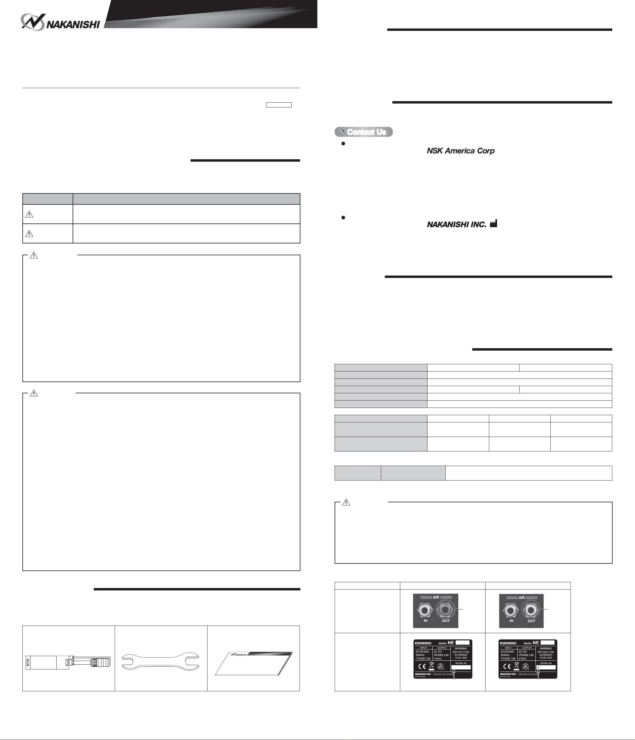
Table. 1 Packing List Contents
Brushless Motor・・1pc. Wrench (22 x 27) ・・1pc. Operation Manual・・1set
27
22
ྲྀᢅㄝ᭩
OPERATION MANUAL
WARRANTY3.
We provide a limited warranty for our products. We will repair or replace the products if the cause of failure is due to
the following manufactures defects. Please contact us or your local distributor for details.
①Defect in manufacturing.
②Any shortage of components in the package.
③Where damaged components are found when initially opening the package.
(This shall not apply if the damage was caused by the negligence of a customer.)
CONTACT US4.
For your safety and convenience when purchasing our products, we welcome your questions.
If you have any questions about operation, maintenance and repair of the product, please contact us.
Company Name
Business Hours
U.S. Toll Free No.
Telephone No.
Fax No.
Web Address
:Industrial Div.
: 8:30am to 17:00pm (CST)
(closed Saturday, Sunday and Public Holidays)
: 800-585-4675
: 847-843-7664
: 847-843-7622
: www.nskamericacorp.com
Contact UsContact Us
For U.S. Market
Company Name
Business Hours
Telephone No.
e-mail Address
:
: 8:00am to 17:00pm
(closed Saturday, Sunday and Public Holidays)
: +81 (0) 289-64-3520
For Other Markets
FEATURES5.
①The Brushless Motor housing is made from precision ground, hardened, stainless steel (SUS) with an outside
diameter of ȭ30mm.
②Excellent durability and high reliability are obtained by using a high-speed brushless motor, which eliminates
the need for brush replacement and frequent maintenance.
③A quick disconnect cord is available for easy Brushless Motor removal.
④Air-cooling system with a small volume of air (30ℓ/ min) is used to prevent heat buildup and allows long
continuous operation.
SPECIFICATIONS AND DIMENSIONS6.
6 - 1 Speci¿cations
Model EM - 3030T - J EM - 3030T - J - 2M
Maximum Motor Rotation Speed 30,000min-1 (rpm)
Max. Output 350W
Quick Disconnect Cord Length 0.3m 2.0m
Weight 415g (without Motor Cord)
Noise Level at 1m distance Less than 70dB (A)
Temperature Humidity Atmospheric Pressure
Operation Environment 0 - 40°CMAX.75%
(No condensation) 800 - 1,060hPa
Transportation and Storage
Environment -10 - 50°C 10 - 85% 500 - 1,060hPa
<Option>
Motor Cord
*Note EMCD - 3000J - □M Cord Length : 3m, 3.7m, 5.7m, 7.7m
( The Air Hose (ȭ4mm) of the same length is attached.)
*Note : Motor Cord is sold separately.
Please select the suitable motor cord length for your application.
・Do not exceed the Maximum Motor Rotation Speed (Refer to " 6 - 1 Speci¿cations " ).
・Motor Cord <EMCD - 3000J - 8M> is not to be used with the Brushless Motor <EM - 3030T - J - 2M>.
・This Brushless Motor should be connected to the Applicable CONTROLLER (Refer to " Table. 2
Identifying the Applicable CONTROLLER ").
If this Brushless Motor is connected to non applicable CONTROLLER, the Brushless Motor will
not rotate and Error " EL " (Incompatible Motor) will be displayed on the Digital Speed Indicator,
indicating a " Detection of unsafe operating conditions " of the CONTROLLER.
CAUTION
Table. 2 Identifying the Applicable CONTROLLER
Identifying Point Applicable CONTROLLER Non applicable CONTROLLER
Color of Air Output Joint
First letter of the Serial
No. on the Rating Plate
Blue White
First letter : Other than " D "
XXXXXXX
First letter : " D "
DXXXXXXX
EM - 3030T - J
EM - 3030T - J - 2M
OM-K0675E 001


