Sherpa BPS-Kompakt 3.0 User manual
BPS – K – 3.0 – 6.0 Sherpa Autodiagnostik page: 1
Operating Manual for
Roller Brake Tester
BPS-Kompakt- 3.0 to 6.0

BPS – K – 3.0 – 6.0 Sherpa Autodiagnostik page: 2
Despite careful content verification e cannot guarantee that this edition is free of errors.
This manual is intended for users ith previous technical kno ledge in the field of vehicle testing technology.
version BA-BPS-K-3.0-6.0-D-120225
language: English
Date: 25.02.2012
© Sherpa Autodiagnostik GmbH
Am Industriepark 11
D-84453 M hldorf
Telephone: +49 (0) 8631 3766 -0
Telefax : +49 (0) 8631 161650
Internet: http://www.sherpa.de
E-Mail: inf[email protected]
All rights reserved.
Technical modifications and all content contained herein are subject to change.

BPS – K – 3.0 – 6.0 Sherpa Autodiagnostik page: 3
.Contents
1. Important Basic Information.................................................. 7
1.1 Scope of Delivery............................................................................................... 7
1.2 Additional Equipment........................................................................................ 7
1. Responsibilities of the Manufacturer in accordance with .............................. 7
1.4 Responsibilities of the Operator ...................................................................... 7
1.5 External Interfaces ............................................................................................ 7
1.6 Legal Information .............................................................................................. 8
1.7 Documentation .................................................................................................. 8
1.8 Conventions....................................................................................................... 8
2. Safety .................................................................................... 10
2.1 Safety guidelines ............................................................................................. 10
2.2 Behaviour in the case of an emergency......................................................... 10
2. Purpose and Use ............................................................................................. 10
2.4 Requirements for the Personnel .................................................................... 10
2.5 Health and Safety at Work............................................................................... 10
2.6 Safety-relevant environmental conditions..................................................... 11
2.7 Assembly and Disassembly............................................................................ 11
2.8 Disposal ........................................................................................................... 11
2.9 Compliance with the Operating Manual......................................................... 11
2.10 Safety markings on the machine .................................................................... 11
2.11 Remaining risks and safety precautions ....................................................... 11
. Technical Information .......................................................... 12
.1 Identification .................................................................................................... 12
4. Description of the system.................................................. 12
4.1 Range of Application....................................................................................... 1
4.2 Main Component ............................................................................................. 14

BPS – K – 3.0 – 6.0 Sherpa Autodiagnostik page: 4
4.3 Modes of Operation ......................................................................................... 16
5. Installation Requirements.................................................... 17
5.1 Installation........................................................................................................ 17
5.2 Fun tional Des ription.................................................................................... 17
5.3 Des ription of the Pro ess ............................................................................. 17
5.4 Display Units.................................................................................................... 17
5.5 Assembly Site .................................................................................................. 18
5.6 Delivery and Installation Requirements of the Test Stand ........................... 18
5.7 Installation Plan ............................................................................................... 18
5.8 Entire Spa e Requirement .............................................................................. 18
5.9 Dimensions and Weights ................................................................................ 18
6. Assembly and Installation, Initial Commissioning............. 19
6.1 Assembly Requirements ................................................................................. 19
6.2 Safety................................................................................................................ 19
6.3 Assembly and Installation............................................................................... 19
6.4 Calibration devi e in a ordan e with ISO 17025......................................... 19
6.5 Initial Commissioning ..................................................................................... 19
6.6 Option lifting and lowering devi e ................................................................. 20
6.7 Option Remote Control ................................................................................... 20
7. Operation ............................................................................ 212
7.1 Safety................................................................................................................ 22
7.2 Operating Elements......................................................................................... 22
7.3 Display Units.................................................................................................... 23
7.4 Operation of the Test Stand............................................................................ 24
7.5 Modes of Operation ....................................................................................... 234
7.6 Remote Control................................................................................................ 25
7.7 Motor y le brake test (option)........................................................................ 25

BPS – K – 3.0 – 6.0 Sherpa Autodiagnostik page: 5
7.8 „Automatic all-wheel drive detection“ (option) ............................................. 25
7.9 Electronic ontrol Box - General View .......................................................... 26
7.10 Test procedure automatic all-wheel drive detection................................... 267
8. Brief Operating Instructions................................................ 28
8.1 Start up the test stand..................................................................................... 28
8.2 Entering the test stand.................................................................................... 28
8.3 Brake Test ........................................................................................................ 28
8.4 Leaving the test stand.................................................................................... 28
8.5 losing-down................................................................................................... 28
9. Trouble Shooting.................................................................. 29
9.1 Safety................................................................................................................ 29
9.2 Service Address............................................................................................... 29
9.3 Location and marking of fuses....................................................................... 29
9.4 Error type detection......................................................................................... 29
9.5 Error checklist ................................................................................................. 29
10. Maintenance and Repair ...................................................... 32
10.1 Safety................................................................................................................ 32
10.2 Proof of Maintenance ...................................................................................... 32
10.3 ontrol Process and Testing Devices............................................................ 32
10.4 Inspection and Maintenance Plan .................................................................. 32
10.5 Specification of the Inspection and Maintenance Plan................................. 32
11. Disassembly and Disposal .................................................. 33
11.1 Safety................................................................................................................ 33
11.2 Disassembly................................................................................................... 323
11.3 Description of Disoposal Work....................................................................... 33
12. omplementary Documentsränzende Unterlagen ............. 34

BPS – K – 3.0 – 6.0 Sherpa Autodiagnostik page: 6
12.1 Drawings and Layouts..................................................................................... 34
12.2 Foundation and Installation Plans.................................................................. 34
12.3 Spare Parts and Consumables ....................................................................... 34
12.4 lectronic Documentation .............................................................................. 34
12.5 Operating Manuals for the options................................................................. 34
12.6 Test Reports..................................................................................................... 34
12.7 Service Address............................................................................................... 34
13. C Declaration of Conformity.............................................. 35
14. Notes ..................................................................................... 36

BPS – K – 3.0 – 6.0 Sherpa Autodiagnostik page: 7
1. Important Basic Information
1.1 Scope of Delivery
1.1.1 Basic Equipment:
- set of rollers
- electric control bo
- display
- manual for operating instructions
1.2 Additional Equipment:
- remote control (infrared)
- pedal force meter
- simultaneous display (analog), several simultaneous displays possible via bus system
- digital display “Sherlane“
- printer
- weighing unit with four dynamometers per set of rolls
- heater of control bo
- heater of set of rolls
- PC converter bo with software „SharlanePC“
- radio pressure converter
- automatic all-wheel drive detection
- ASA-Livestream Set
1.3 esponsibilities of the Manufacturer in accordance with:
- Machinery Directive 2006/42/EC of May 17, 2006
- EMC Directive 2004/108/EC of December 15, 2004
- Low Voltage Directive 2006/95/EC of December 12, 2006
- Directive Vkbl. (official gazette of the Federal Ministry of Transport, Building and Housing in
Germany) 2003 / p. 303 for the operation, condition and testing of brake testers
- EC Directive CE marking
- DIN EN 60204-1 electronic equipment of the machines
- GS-EM I 04 - 01 and BGR (the German Federal Institute for Geosciences and Natural
Resources) 157 auditing standards for machines and devices responsible for vehicle
maintenance and for testing vehicles
- EC-declaration of conformity
1.4 esponsibilities of the Operator
- The machine may only be installed by competent and qualified personnel.
- The machine may only be used in accordance with its intended purpose.
- This operating manual must be read carefully in its entirety before commissioning the machine.
Keep these instructions within reach at all times.
- Personal injuries which are a result of the non-compliance with this operating manual are not
covered by the Product Liability Act.
- Sherpa does not assume liability for any damage to the test unit or the vehicle that was caused
due to non-compliance with this operating manual.
- Safety guidelines warn of potential risks and help to avoid personal injuries and damage to
properties. For your own safety, it is imperative that you adhere to the safety guidelines set out in
this manual.
- The national and international safety regulations applicable in the respective country of operation
must be adhered to at all times. Every operator himself/herself is responsible for complying with
the regulations applicable to him/her and for obtaining independently the respective current
regulations.
- The operating manual is part of the machine.
- The operating manual must be maintained and updated throughout the entire service life of the
machine.
- The operating manual must be forwarded to any subsequent owner of the machine.
1.5 External Interfaces
- Interfaces for computer connection
BPS – K – 3.0 – 6.0 Sherpa Autodiagnostik page: 8
1.6 Legal Information
1.6.1 Limitation of Liability
- Our liability is li ited to the foreseeable da ages typically occurring under the contract. We shall
only be held liable for da age caused deliberately or due to gross negligence.
- The above li itation on liability does not apply in the event of injury to body or health.
- Any entitle ent to da ages expires regularly, two years after the ti e that it beca e justifiably
clear that da age had occurred, or at the latest ten years after the da age occurred.
1.6.2 Warranty
- We warrant that our products are free fro defects for a period of 12 onths fro the date of
delivery to the purchaser. This does not apply for the delivery of used products. Any warranty is
excluded here.
- Within the scope of the warranty, we are entitled to li it our responsibilities to provide a re edy
and/or a replace ent delivery at our own discretion.
- We accept no liability for any consequential da age or lost profits.
- All parties to the contract reserve the right to rescind the contract in the case of any unsuccessful
atte pt to re edy defects and/or any i possible replace ent delivery.
1.7 Documentation
1.7.1 Operating Instructions – in accor ance with DIN EN 62079
- The following docu ents, if not already included in the operating anual, are at your disposal:
- Operating Manual: option „auto atic all-wheel drive detection“
- Re ote control Mechoscreen – brief instructions
- SherlanePC oparating anual
- ounting and installation instructions
- electrical circuit diagra
- aintenance and service instructions (including the Calibration Manual and the test report of the
routine test)
- list of spare parts
1.8 Conventions
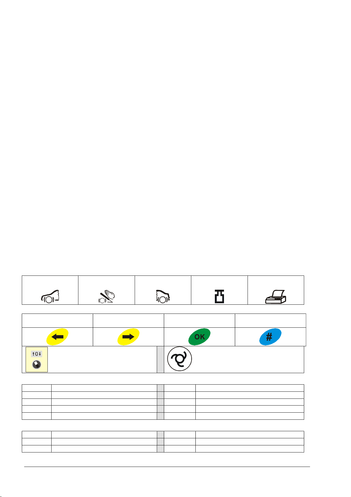
1.8.1 Illustration
front axle parking brake rear axle entire weight printout
left right confir select device
- direction of rotation and
easure ent reversal of the rollers
auto atic button
toggle function for „auto atic ON or
OFF“ and STOP
1.8.2 Abbreviations
BPS brake tester e- otor electric otor
L / R left / right kW kilowatt
kN kilo Newton kg kilogra
k /h kilo etres per hour
LED digital indicator light
1.8.3 Technical Terms
SB service break FSB parking brake
PM pneu atic charge pressure PX pneu atic brake cylinder pressure
DMS strain gauge

BPS – K – 3.0 – 6.0 Sherpa Autodiagnostik page: 9
2. Safety
2.1 Safety guidelines
- According to the manufacturer s declaration the "PRINCIPLES about testing the safety of roller
brake testers and roller dynamometers" (GS-EM I 04-01), as well as the auditing standards for
machines and devices responsible for vehicle maintenance and for testing vehicles (BGR 157)
were taken as a basis during the production of the brake tester.
- This operating manual must be read carefully in its entirety before commissioning the machine.
Keep these instructions within reach at all times.
- Personal injuries which are a result of the non-compliance with this operating manual are not
covered by the Product Liability Act.
- Sherpa does not assume liability for any damage to the test unit or the vehicle that was caused
due to non-compliance with this operating manual.
- Safety guidelines warn of potential risks and help to avoid personal injuries and damage to
properties. For your own safety, it is imperative that you adhere to the safety guidelines set out in
this manual.
- The national and international safety regulations applicable in the respective country of operation
must be adhered to at all times. Every operator himself/herself is responsible for complying with
the regulations applicable to him/her and for obtaining independently the respective current
regulations.
Danger: If instructions are not followed carefully or not complied with, the personal safety
can be put at risk.
Warning: If these instructions are not followed carefully or not complied with, the device
might be damaged.
Please note: Additional information will be provided.
2.2 Behaviour in the case of an emergency
- In the case of a dangerous situation or an emergency, the test stand must be shut down by
means of the main switch (emergency stop function) at the electric control box.
2.3 Purpose and Use
- The roller brake tester can be used to test the brake systems of two-track vehicles.
- The test stand may only be used in accordance with its designated purpose and within its
performance limits.
- The measured brake force is indicated separately for each wheel.
- The test stand is not designed for testing all-wheel drive or multi-axle vehicles. However, all-
wheel drive vehicles can be tested on some conditions.
2.4 Requirements for the Personnel
- The test stand may only be operated by authorized qualified personnel.
- The test stand may only be operated by trained qualified personnel.
2. Health and Safety at Work
- main switch: A lockable main switch (emergency switch) is available.
- sensor rolls: The test unit only starts if both sensor rolls are pushed down within 2
seconds .
- step protection: protection sheets are installed beneath the sensor rolls.

BPS – K – 3.0 – 6.0 Sherpa Autodiagnostik page: 10
2.6 Safety-relevant environmental conditions
- The V-shaped slot bet een the rollers must be secured by a cover or an elevated step
protection.
- If the repair pit is under construction and the test unit in operation, no person is allo ed to stay in
the area belo the vehicle.
- Depending on the national regulations, the repair pit must be covered or secured by other means
for access.
2.7 Assembly and Disassembly
- see "assembly, installation, initial commissioning"
2.8 Disposal
- The transmissions of the driving engines are filled ith oil hich must be disposed of separately.
- Electronic circuit boards must be disposed of separately.
- This also applies for remote controls and printers.
- Sheet metal and iron parts are scrap metal.
2.9 Compliance with the perating Manual
- The operating manual must be complied ith at all times.
- The operating manual must al ays be kept close to the machine and be available to the entire
personnel of the machine at all times.
- If applicable, the operating manual must be for arded to any subsequent o ner of the machine.
2.10 Safety markings on the machine
- The roller sets of the testing facility must be marked ith circumferential arning markings on the
floor or be secured by a barrier.
- The option "automatic all- heel drive detection" is indicated on the control box.
2.11 Remaining risks and safety precautions
- Bet een the drive rollers is a V-shaped slot in hich the sensor roll moves. Depending on the
set-up area of the test unit, the test unit must be covered or fenced off to prevent access.
- If the drive rollers are elevated, there is a risk of tripping over.
- The test unit is equipped ith rollers hich are independently driven by electric motors. While the
rollers are spinning nobody is allo ed to be in the direct vicinity of the rotating rollers.
- After the vehicle has been driven onto the test stand, shift into neutral to disconnect the po er
flo to the drive axles.
- No parts or heels must be parked on or bet een the test rollers.

BPS – K – 3.0 – 6.0 Sherpa Autodiagnostik page: 11
3. Technical Information
3.1 Identification:
- The complete e uipment of the test unit is identified by a type label on the control box as well as
by means of the following information on the roller set:
- manufacturer -type and version -serial number - year of manufacture
- power in kW -power supply in V and ACNPE -current consumption measured in A
- In addition, each unit (set of rolls, display, print box, etc.) has its own serial number.
3.1.1 The entire system
permissible humidity up to 85 %
operating temperature -10° to +60°
point zero adjustment when ready for operation every 2 minutes
3.1.2 Display cabinet
housing dimensions width x depth x height (mm) 810 x 670 x 70
weight 10 kg
braking force display 0 - 6 kN (0 – 12)
diameter of the needle-analogue display 400 mm
subdivision 180°
smallest increment 100 N
type size 25 mm
3.1.3 Control box
power supply 3 x 400 V (AC)
permissible fluctuation of the nominal voltage ± 10 %
protection 3 x 20 Ampere slow
supply lead 5 x 2.5 mm²
3.1.4 Set of rolls compact 3.0 3. 6.0
one-piece frame width x length x depth (mm) 2260 x 580 x 195 2320 x 680 x 240 2925 x 680 x 240
approx. weight in kg 290 440 640
length of rollers in mm 600 700 1000
diameter of rollers in mm 167 205 205
track gauge 820 x 2160 800 x 2200 800 x 2800
distance between the axes of the rollers 380 410 mm 400
crossing capacity on middle cap, max. wheel
load in kg
550 550 550
test speed in km/h 2.7 4.8 4.8
coefficient of friction dry / wet 0.9 / 0.7
measuring system, shear force transducer
DMS
with integrated measuring reinforcement
noise emission LWA <70 dB (A)
welded roller surface welding rod
measurable axle load (for a deceleration of
50%) in kg
2000 2000 2450 / (4800)
measurable axle load (option of 2x4 kW
motors) in kg
2450
max. axle load on rollers in kg, when vehicle
enters the test stand
3000 4000 5000 / (6000)
output of the driving engines in kW 2 x 2.4 2 x 3 kW 2 x 4
voltage supply in mm² / A 5 x 2.5 / 16 5 x 2.5 / 20 5 x 2.5 / 20

BPS – K – 3.0 – 6.0 Sherpa Autodiagnostik page: 12
4. Description of the System
4.1 Range of application
- The roller rake tester can e used to test the rake systems of one- and two-track vehicles and
has a certification for the vehicle inspections in accordance with § 29 StVZO (German road traffic
licensing authority) in relation with appendix VIII main inspections.
- The right and left rakes will e inspected independently.
4.1.1 Requirements in accordance with Directive 10/2011
ith effect from October 01, 2011, only roller brake testers with the following option will be
allowed in Germany, in accordance with the directive 10/2011 for vehicle inspections in
accordance with § 29 StVZO.
- The minimum diameter of the test rollers is 200 mm.
- slip measurement with additional speed sensors on sprocket wheels
- For vehicles of the category M1 or N1 ( elow 3.5 t in weight permitted), the minimum test speed
is 4 km/h. For test stands with a lower test speed, the option "two test speeds" is availa le.
- ASA-Livestream interface
SVZ 210142 ASA-Livestream Set for Sherpa-BPS (in accordance with Directive 10/2011
Germany)
Scope of Delivery: Converter for BPS control box
(RS 485 with USB port), speed sensor for rake rollers
4.1.2 ASA-Livestream Set
- In the control ox is a ca le with an integrated ASA-Livestream converter. One end of this ca le
is connected to the RS 485 interface (connector for all kinds of displays) and the other end has
an USB plug for the data transport to the external computer.
- In addition to the two speed sensors at the sensor rolls, two speed sensors are installed at the
sprocket wheels.
ith the option "ASA-Livestream Set" Sherpa's test stands of the type range BPS-Kompakt-
3.5 to 13.0 and BPS-Twin are in accordance with the Directive 10/2011.
4.1.3 Vehicles with or without the option to disengage the all-wheel drive system
- can e tested.
4.1.4 Vehicles with a permanent all-wheel drive
- The following requirements determine whether it is possi le to test all-wheel drive vehicles whose
wheels, which are mounted on one axle, can each e rotated in the opposite direction.
- Whether all-wheel drive vehicles can e tested, depends on some conditions.
- All-wheel drive vehicles with a low power transmission or whose all-wheel drive system can e
disengaged in the test stand can e tested (also see the manufacturer's note in the manual a out
the test procedure in relation to the integrated automatic start-up monitoring).
- All-wheel drive vehicles with a high rate of power transmission (rigid or "quasi rigid" drive system)
during the rake test cannot e tested.
4.1.5 Automatic all-wheel drive detection (option)
- For a rake test in which multi-axle vehicles are tested on roller rake testers, it is common
practice to enter the test stand with the wheels of one axle to rest etween the test rollers and to
evaluate the rake force of the two wheels spinning forwards.
- For all-wheel drive vehicles with a rigid or quasi-rigid drive system serious pro lems can occur.
- Depending on the amount of power which is transmitted to the wheels, the vehicle is driven out of
the test rollers y means of the other driving axles, or an increased rolling resistance acts on the
axle which is to e tested as a result of the intervention of the all-wheel system. This increased
rolling resistance can highly distort the measuring results of the rake test.
- For vehicles with a multi-axle drive, the rake force of any wheel rake can e transferred to the
other wheel rakes via the drive train depending on the drive system. However, if the wheel
rakes of passenger cars or trucks are tested, the rake force of the individual wheel rakes is to
e evaluated, not the transmission of the rake force via the drive train.
- In order to reduce these forces it has een common practice for a long time to test the wheels of

BPS – K – 3.0 – 6.0 Sherpa Autodiagnostik page: 13
the axle which is to be tested in such a ashion that one side is turning orwards and the other
side backwards.
- Due to the great number o the most diverse all-wheel drive systems, it has become very di icult
or the skilled person in this ield to recognize at once which type o test needs to be carried out
or the respective drive system – either both wheels on the axle turning orwards or reverse the
direction o rotation on either side.
- Due to our new system the operator does no longer need to make a decision. This system
automatically recognizes at the start o the test i the vehicle's driving axles can rotate reely or i
they are connected to an all-wheel drive system.
- For a vehicle with a single-axle drive, both wheels on the roller brake tester start spinning in one
direction and i the vehicle is set in idle condition, the drive sha t can rotate reely without
transmitting power to the wheels. I the axle sha ts o the axle which is connected to the drive
wheels are slowed down by the drive sha t, as it is the case with an all-wheel drive system or
an engaged gear, the di erential o the axle causes the opposite wheel to turn in the other
direction.
- One side o our test stand starts, as a rule, slightly earlier or later than the other, whereas the le t
wheel starts turning orwards. I the drive sha t is orced to slow down, the right wheel will turn
one revolution in the opposite direction, which will immediately be detected by the brake orce
measuring system. Then the right wheel automatically starts turning in the opposite direction and
the display automatically shows a positive measured value.
- As most "all-wheel drive vehicles" are equipped with disc brakes, the pedal orce meter is not
necessary to measure the di erence o the brake orce in reverse direction o rotation. The
di erence between the brake orce o the disc brakes rotating orwards and backwards is very
small.
- The time in which the vehicle is being tested is the same as for single-axis driven
vehicles. Slightly more time will be needed only i the test unit automatically carries out a cross-
check.
- I the braking orce imbalance is too high, another check is carried out in the reverse rotational
direction. In this case the two values o the braking orce imbalance o both checks are compared
with each other. The threshold value or the cross-check can be saved in the program.
4.2 Main Component
- The standard equipment o the test unit includes a sel -contained or a two-part roller set, a
control box and a moving-needle analogue display or a PC converter box.
4.2.1 Set of rollers
- The standard roller sets are hot-dip galvanized.
- The roller sets are available as self-contained or two-part models. A two-part set is mainly
used or test stands on a repair pit.
- The self-contained roller set is a compact unit which is equipped with our rollers and a drive
and measuring unit in the middle area o the test stand which includes gear motors, sprocket
wheels, a chain and a DMS sensor.
- The two-part roller set contains two roller sets with two rollers each and a drive and measuring
unit which is mounted on the side.
- The pairs of rollers are each driven by an electric motor which is mounted on swivel bearings
and can trans er the occurring torsional orces to a bending beam.
- The bending beam has a DMS sensor which orwards the measured values to the printed circuit
board in the control box or the electronic measured value processing.
- The rollers are made o steel pipes with a welded-on pro ile.
- Sensor rolls are built in between the rollers. The sensor rolls are mounted in swivel bearings and
are pushed down by the wheel and pulled up again by a spring a ter the vehicle has le t the test
stand. By means o proximity switches the situation or "vehicle in test stand" or "test stand
empty" can be recognized and the test stand can be started and stopped in automatic mode.
- The rotational speed o the wheels is measured by means o the rotating sensor rolls. I the
di erence between the rotational speed o the wheels and the input speed is about 25% (slip),
the test stand will be switched o or sa ety reasons.

BPS – K – 3.0 – 6.0 Sherpa Autodiagnostik page: 14
- The roller sets only rest on the set s rews whi h are atta hed to the four orners underneath.
By this means the roller set an be adjusted in height up to minus or plus 10 m. In order to
prevent the set s rews from being in dire t onta t with the on rete underneath, the roller set
omes with metal sheets. These onta t sheets have to be atta hed to the side of the foundation
by means of dowels.
- The option weighing unit in ludes sensors whi h are atta hed next to the s rew holes. In this
way the set s rews an be s rewed into the sensors.
- To prevent the roller sets from slipping, the roller sets are firmly atta hed to the foundation by
means of adjusting s rews at the side. If the weighing unit is in operation, the roller set must
not be atta hed to the foundation firmly but built in leaving a small gap between the set s rews
and the foundation wall.
4.2.2 Control Box
- The control box is the brain of the test unit. There are printed ir uit boards, onta tors, the
main swit h (emergen y swit h-off) and other swit hes or buttons in the ontrol box. See
operating manual.
- For this reason the control box should be mounted in the dire t vi inity of the roller set.
- The analogue displays, the PC onverter box and the print box are onne ted to the ontrol box.
- The whole data transfer happens in the bus system.
- Self test zero balance: A permanent self test is arried out by all safety-relevant omponents
(sensors and ele troni s) ready for operation. A drift in temperature in for e transdu ers will be
ompensated for by a dynami point zero adjustment. This adjustment is arried out regularly
every 2 minutes when the for e transdu ers are not in use and ready for operation.
- Natural frequency attenuation: The measuring steps are smaller than 1 % of the final
measuring range value.
- Functional defects: Fun tional defe ts are re ognized and illustrated by the ele troni s. They
an be identified with the help of the error he klist. (see operating manual)
4.2.3 Illustration and printout of the measurement results
- The moving-needle analogue display onsists of two neighbouring displays indi ating the
braking for e for left and right respe tively. It an be used either as a master or a simultaneous
display.
- For the PC converter box whi h uses the „SherlanePC“software, an external PC unit in luding
a display is ne essary.
- Printing an be a hieved via the PC unit or by means of the option "print box" via a separate,
onventional printer. After the ompletion of the test pro edure in every operating mode (see
se tion 3.12), use the omputer keyboard or the remote ontrol to print.

BPS – K – 3.0 – 6.0 Sherpa Autodiagnostik page: 15
4.3 Modes of Operation
4.3.1 Manual Operation
- manual control o the test unit by means o the remote control (in rared) or by means o a button
on the control box
4.3.2 Automatic Mode
- automatic test run start
4.3.3 Option of direction of rotation and measurement reversal
- With this option it can be preselected by means o the switches at the control box i the wheels
are to be turned in the same direction, i.e. orwards or backwards, in opposite directions or i only
one wheel is to be rotated.
4.3.4 Automatic all-wheel drive detection:
- In this operating mode (right and le t switch are set to the position "0") the test stand recognizes i
there is a transmission o power between the le t and the right wheel. I the wheels which are
attached to one axle cannot turn independently, the test stand automatically changes over to
reverse mode o direction o rotation (le t orwards / right backwards). During this type o testing
the green LED lashes to indicate that the test stand is in operation.
- I the di erence o the maximum brake values is higher than 15 % rom le t to right, the green
LED continues lashing and a cross-check in reverse mode is carried out.
- A ter the LED stops lashing, the brake values o the wheels turning orwards and the
corresponding di erence will be displayed.
- Note: The value o the braking orce imbalance or the cross-check in reverse mode can
be customized in the calibration mode.

BPS – K – 3.0 – 6.0 Sherpa Autodiagnostik page: 16
5. Installation Requirements
5.1 Installation
5.1.1 Main Components
- set of rollers
- control bo
- display
5.1.2 Operators' Workplaces
- test stand
- office
5.2 Functional Description
- The roller brake tester can be used to test the brake systems of two-track vehicles and has a
certification for vehicle inspections in accordance with § 29 StVZO in relation with appendi VIII
main inspections
- The right and left brakes will be inspected independently.
- The pairs of rolls are each driven by an electric motor which is mounted on swivel bearings and
transfers the occurring torsional forces to a bending beam.
- The integrated microprocessor control evaluates the measuring results.
- The rotational speed of the wheels is measured by means of the rotating sensor rolls. If the
difference between the rotational speed of the wheels and the input speed is about 25% (slip),
the test stand will be switched off for safety reasons.
5. Description of the Process
5. .1 Set of Rollers
- Depending on the version, the roller set is available as a self-contained or a two-part model. Two-
part roller sets are primarily used when installed on top of repair pits. Depending on the national
regulations, safety elements are required for securing the pit during the construction of the pit.
- Depending on their design, self-contained roller sets can be mounted into a foundation or at floor
level with ramps. If the roller set is installed at floor level, access and e it ramps are required.
- The roller set is pre-wired and has to be connected to the control bo .
- The display units are to be connected with the control bo .
5. .2 Control Box
- The main power supply must be on site where the control bo has been installed.
5.4 Display Units
- The display units are connected to the control bo .
5.4.1 Moving-needle analogue display
- The moving-needle analogue display is equipped with a retaining clip. It can be mounted on a
foot or attached to the wall by means of wall brackets.
- It must be mounted in such a fashion that it can clearly be seen when sitting in the vehicle.
5.4.2 PC-Display Units
- In general, the information defined by the manufacturer of the PC display needs to be followed.
- When operated in connection with a needle display, the PC display can be mounted somewhere
out of sight of the vehicle, up to a distance which is in range of the customary connection
devices.
- Without any needle display the PC display should be mounted in sight of the testing area.

BPS – K – 3.0 – 6.0 Sherpa Autodiagnostik page: 17
5.5 Assembly Site
5.6 Delivery and Installation Requirements of the Test Stand
- The location here the test unit is to be installed must be ell accessible for transport vehicles or
equipment.
- For unloading, moving and inserting equipment on the assembly or erection site, a mobile
mechanical lifting equipment, hich can carry the eight of the test unit, must be provided by the
client.
- The client shall ensure that the installation site is not surrounded by a hazardous environment.
5.6.1 Foundation and Floor
- Requirements for the foundation and the floor load capacity is specified in the corresponding
foundation and installation plans.
5.6. Environmental Conditions
- The test stand can also be operated outdoors and meets the requirements of the IP 54 protection
rating (dust and splashing ater protected). It is designed for the operating temperatures of
minus 10° C up to 60° C.
- The roller set must not be under ater.
- For the force transducer, the manufacturer of the component specifies a susceptibility to a
temperature of 0.04 %/K° (for a temperature of > 22° C) of the final calibration value or the
nominal value to be measured.
- When operated outdoors, a roof construction is required as stipulated by the manufacturer of the
display unit. If used at temperatures of minus 0° C and surrounded by sno , a heater is required
for the set of rolls.
5.6.3 Power supply leads
- The main po er supply has to be on site here the control box has been installed.
- For some options, an air connection is also required.
- The range of po er of the supply leads is specified in the corresponding foundation and
installation plans.
5.7 Installation Plan
5.7.1 Set of Rollers
- Depending on the version, the roller set is available as a self-contained or a t o-part model. T o-
part roller sets are primarily used hen installed on top of repair pits. Depending on the national
regulations safety elements are required for securing the pit during its construction.
- Depending on their design, self-contained roller sets can be mounted into a foundation or at floor
level ith ramps. If the roller set is installed at floor level, access and exit ramps are required.
- The roller set is pre- ired and has to be connected to the control box.
- The display units are to be connected ith the control box.
5.7. Control Box
- The control box should be mounted in the direct vicinity of the roller set.
5.7.3 Moving-needle analogue display
- The operator should have a good vie on the display unit from the position of the vehicle during
the entire testing operation.
- The needle display can be erected outdoors; ho ever, it must be protected from ind, ater and
damaging environmental impacts.
5.8 Entire Space Requirement
- Ho much space is required for the entire equipment depends on the size of the vehicles hich
are to be tested.
5.9 Dimensions and Weights
- see technical documentation

BPS – K – 3.0 – 6.0 Sherpa Autodiagnostik page: 18
6. Assembly and Installation, Initial Commissioning
6.1 Assembly Requirements
- The test stand can onl be assembled and installed if the temperature and environmental
conditions are tolerable and if adequate working conditions appl .
- Safe working conditions must be provided on the assembl site.
6.2 Safety
- The test stand ma onl be installed b competent and qualified personnel.
- The set of rolls is equipped with a step protection underneath the sensor rolls.
- The middle cover of compact test stands can carr a maximum load of 500 kg.
6.3 Assembly and Installation
6.3.1 isplay cabinet
- Mount the needle displa at the designated location.
- For outdoor operations, a roof construction is required.
- Connect the power suppl cord with the European-st le terminal strip which has three contacts
and run the cord to the control box.
- Connect the bus cable with the PCB of the displa unit and run it to the control box.
6.3.2 Screen
- The test unit can be operated using either one moving-needle analogue displa or a computer
with a screen or both at the same time.
- If the computer and the screen are used, please follow the information specified b the
manufacturer of the computer and our operating manual "SherlanePC".
- For the data transfer from the test units to the PC, the option "PC converter box with the
Sherlane test lane software" is necessar .
- One side of the PC converter box is connected to the control box and the other one with the
serial interface at the computer.
6.3.3 Control box
- The control box must be mounted near the set of rolls.
- Connect the suppl lead with the main switch in the control box.
- Connect the bus cable of the displa with the PCB of the control box.
- Connect the power suppl cord of the displa with the terminal strip.
6.3.4 Set of Rolls
- Disassemble the middle cover of the roller set and heave it to the side.
- The upper side of the roller set has threaded slots into which e ebolts can be screwed. The set of
rolls is attached to these e ebolts and hoisted into the foundation b means of mechanical lifting
equipment.
- Large arrows are attached to the roller sets which indicate the main driving direction. The roller
sets must be mounted in the main driving direction, even if the optional directional rotation and
measurement reversal is available.
- Hoist the roller set into the pit and use the set and adjusting screws to adjust the height and to
firml attach it to the foundation.
- The lifting equipment should be able to carr a
minimum load of 500 kg. Make sure the
maximum inclination angle does not exceed 60°.
- The safet regulations for lifting equipment need
to be followed.
- Run both engine cables to the control box and connect them with the power contactors.
- Run both sensor cables to the control box and connect them with the PCB of the control box.
- Reinstall the middle cover of the roller set.
6.4 Calibration device in accordance with ISO 17025
- see 10.3.2
6.5 Initial Commissioning

BPS – K – 3.0 – 6.0 Sherpa Autodiagnostik page: 19
- Follow the ope ating inst uctions.
6.6 Option lifting/lowering device
SVZ 210085 - Pneumatically ope ated lifting/lowe ing device; if it is employed as a step p otection, a
vehicle with a maximum axle load of 4 t is allowed to d ive ove it.
- the lifting/lowe ing device is automatically lifted o lowe ed due to weight ecognition
SVZ 210085 - The pneumatically ope ated lifting/lowe ing device has a lifting fo ce of up to 2.2 t,
- It can ca y a load of 4 t when the vehicle is d iven ove the test stand; manual lifting
and lowe ing ope ation is ca ied out by means of the automatic button at the cont ol
box (o by means of the option " emote cont ol adio").
6.6.1 Description / Installation
- The lifting/lowe ing device is a completely sepa ate component which needs to be attached to the
set of olls. If olde test units a e upg aded, 4 holes need to be d illed beneath the set of olls on
each side in o de to sc ew the lifting/lowe ing device to it.
- The lifting/lowe ing device is equipped with an ai am which lifts and lowe s the device. In the
middle of the olle set a pneumatic valve which cont ols the ai ams is installed. The pneumatic
valve is cont olled by the PC boa d of the cont ol box.
- The ai supply line is connected to the pneumatic valve. Its supply p essu e needs to be between
6 and 9 ba but if it is highe , a p essu e limite needs to be installed.
6.6.2 Application
- The V-shaped slot between the olle s is cove ed by the "lifting/lowe ing device" in standby mode.
This p ovides us with a safety device which p events people who walk a ound this a ea f om
t ipping ove the b ake olle s.
- If a vehicle is d iven ove a standard test stand, its wheels will est in the V-shaped slot between
the olle s and consequently cause a noise which is pe ceived as unpleasant by some use s. If
the lifting/lowe ing device is elevated, a vehicle of about 4 t can be d iven ove the V-slot cove
without its wheels sinking in between the olle set completely. By this means, the vehicle can be
d iven ove the test stand without causing any noise.
- Vehicles with a low g ound clea ance and spoile s a e gently lowe ed into the V-shaped slot by
means of the lifting/lowe ing device. This p events spoile s and low vehicle components f om
being damaged.
6.6.3 Description
- If the lifting/lowering device is used as a step protection, it is not esponsible fo lifting the
vehicle's wheels out of the gap between the olle s. This would significantly extend the time in
which the vehicle is being tested and equi e a manual ope ation via an actuating switch o a
emote cont ol.
- The vehicle can easily be d iven out of the set of olle s, as we have installed a standa d auxilia y
d ive-off system which p events the olle s f om ove -speeding at all times and hence facilitates
d iving out of the test stand. The set of olle s is equipped with a weight senso and can identify
the axle weight of the vehicle afte an adjustable time delay and the weight has been set and
automatically lifts o lowe s the lifting/lowering device . The efo e, any manual ope ation
becomes unnecessa y.
- The lifting/lowering device can lift the wheels out of the V-shaped slot between the olle s with
a lifting fo ce of 2.2 t axle weight. It is manually ope ated by means of the adio emote cont ol
"Radio"
- The lifting/lowe ing device is ope ated pneumatically with a maximum p essu e of 6-9 ba and is
cont olled elect onically. The standa d time needed to lowe the wheels is about 3 seconds and
can be customized by means of a th ottling valve (optional).
- Please Note: If the test unit is tu ned off and comp essed ai is still in the system, the lifting
device emains elevated.
- If the ai p essu e is less than 2 ba , the outlet valve will not open anymo e. If necessa y, the ai
supply line needs to be disconnected f om the p essu e switch/ automatic button.

BPS – K – 3.0 – 6.0 Sherpa Autodiagnostik page: 20
6.7 Option Remote Control
6.7.1 View
- left
- confi m
- ight
- select device
6.7.2 Description of the Symbols
- left - ight - confi m select device
6.7.3 Initial Commissionin
- The emote cont ol has a echa geable batte y. Between the contacts of the batte y is a
p otection foil which needs to be emoved befo e it can be ope ated.
6.7.4 Functions
- see sepa ate ope ating manual
This manual suits for next models
2
Table of contents


