IE1!1730o
STEREO
POWER
AMPLIFIER
Impedance
AWG
Reslstance
Size
(ohms/1000 feet)
40
80
160
10
1.00.
120
240
480
12
1.59
75
150
300
14
2.50
48
96
190
16
4.02
30
60
120
18
6.39
19
38
75
20
10.1
12
24
48
22
16.2 7
15
30
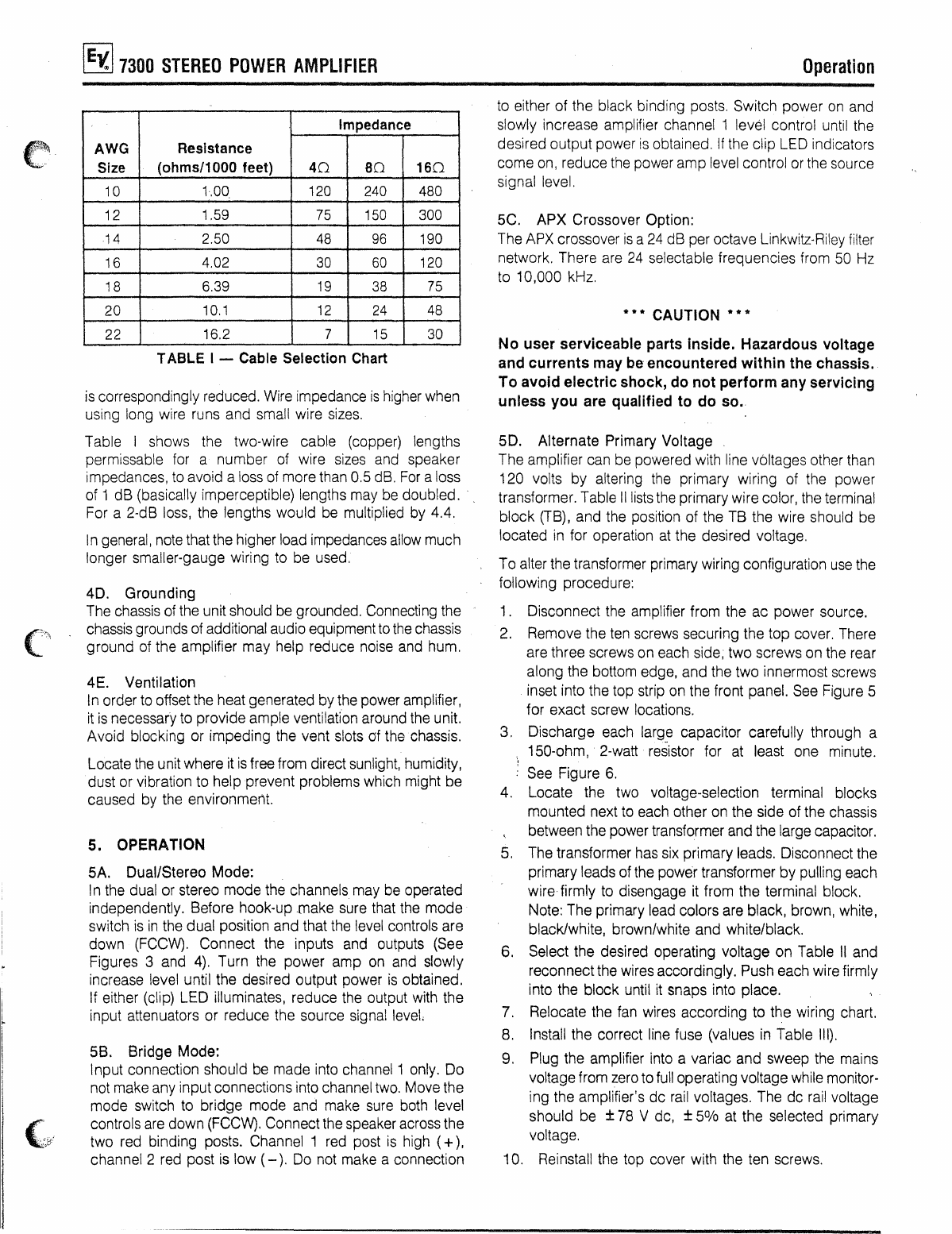
TABlE I - Cable Selection Chart
is
correspondingly reduced. Wire impedance
is
higher when
using long wire runs and small wire sizes.
Table Ishows the two-wire cable (copper) lengths
permissable
for
anumber of wire sizes and speaker
impedances, to avoid aloss of more than 0.5 dB.
For
aloss
of 1dB (basically imperceptible) lengths may
be
doubled. '
For a2-dB loss, the lengths would
be
multiplied by 4.4.
In
general, note that the higher load impedances allow much
longer smaller-gauge wiring to be used,
40.
Grounding
The chassis
of
the unit should
be
grounded. Connecting the
chassis grounds of additional audio equipment
to
the
chassis
ground of the amplifier may help reduce noise and hum.
4E. Ventilation
In
order to offset the heat generated bythe power amplifier,
it
is
necessary to provide ample ventilation around the unit.
Avoid blocking or impeding the vent slots of thechassis.
Locate
the
unit where it
is
free from direct sunlight, humidity,
dust or vibration to help prevent problems
wh
ich might be
caused
by
the environment.
5. OPERATION
5A. Dual/Stereo Mode:
In the dual or stereo mode the channels may be operated
independently. Before hook-up .make sure that the mode
switch
is
in
the dual position and that the level controls are
down
(FCCW).
Connect the inputs and outputs (See
Figures 3and
4).
Turn the power amp
on
and slowly
increase level until the desired output power
is
obtained.
lf either (clip) LED iltuminates, reduce the output with the
input attenuators or reduce the source signal level.
5B. Bridge Mode:
Input connection should
be
made into channel1 only.
00
not make any input connections into channel
two.
Move the
mode switch to bridge mode and make sure both level
controls
are
down
(FCCW).
Connect the speaker ac
ross
the
two red binding posts. Channel 1red post
is
high
(+),
channel 2red post
is
low (
-).
00
not make aconnection
Operation
to
either of the black binding posts, Switch power
on
and
slowly increase amplifier channel 1level control until the
desired output power
is
obtained,
If
the clip
LEO
indicators
come
on,
reduce
the
power amp level control or the source
signal level.
5C. APX Crossover Option:
The
APX
crossover
is
a
24
dB per octave Linkwitz-Riley filter
network. There are
24
selectable frequencies from 50 Hz
to 10,000 kHz,
***
CAUTION
***
No user serviceable parts inside. Hazardous voltage
and
currents
may be encountered
within
the chassis.
To
avoid electricshock, do
not
perform
any servicing
unless you are qualified to
do
so.
50.
Alternate Primary Voltage
The amplifier can be powered with line v6ltages other than
120 volts by altering the primary wiring of the power
transformer. Table Illiststhe primary wire color, the terminal
block
(TB),
and the position of the
TB
the wire should be
located
in
for operation at the desired voltage.
To alter the transformer primary wiring configuration
use
the
following procedure:
1. Oisconnect the amplifier from the ac power source.
2.
Remove the
ten
screws securing the top cover. There
are three screws on each side; two screws on the rear
along the bottom edge, and the two innermost screws
inset into the top strip on the front panel. See Figure 5
for exact screw locations.
3. Discharge each large capacitor carefully through a
150-ohm, 2-watt resistor for
at
least one minute.
See Figure
6.
4. Locate the two voltage-selection terminal blocks
mounted next to each other
on
the side of the chassis
between the power transformer and the large capacitor.
5.
The transformer has six primary leads. Disconnect the
primary leads of the power transformer by pulling each
wire firmly to disengage it from the terminal block.
Note: The primary lead colors are black, brown, white,
black/white, brown/white and white/black.
6. Select the desired operating voltage on Table
11
and
reconnectthe wires accordingly. Push each wire firmly
into the block until
it
snaps into place.
7. Relocate the fan wires according to the wiring chart.
8. Install the correct line fuse (values
in
Table
111).
9. Plug the amplifier into avariac and sweep the mains
voltage from
zero
to
full
operating voltage while monitor-
ing the amplifier's dc
rail
voltages. The dc
rail
voltage
should be ±
78
Vdc, ±
5%
at the selected primary
voltage.
10. Reinstall the top cover with the ten screws.