manuals.online logo
Brands
  1. Home
  2. •
  3. Brands
  4. •
  5. Electro-Voice
  6. •
  7. Subwoofer
  8. •
  9. Electro-Voice T18 User manual

Electro-Voice T18 User manual

T18
Subwoofer
• DL18MT Manifold Technology
TM
woofer for reliable, extended low-
frequency output
• Subwoofer for augmenting the
low-frequency performance of
EV stage systems
• Natural high-frequency roll-off
• 400-watt long-term power capacity
• Rugged, road-ready cabinet; metal
grille; black carpet finish
• Neutrik Speakon
®
and
1
/
4
-inch phone
jack inputs
•1
3
/
8
-inch stand mount in top allows
use of satellite system
Impedance,
Nominal:
8 ohms
Minimum:
6.6 ohms
Input Connectors:
Two Neutrik Speakon®NL4MPR-V and two
1/4-in. phone jacks, all in parallel
Supplied Accessory:
Neutrik Speakon®NL4FC input cable
connector
Mounting:
Top surface contains stand mount
receptacle for use with satellite speaker
system
Materials,
Enclosure:
Black, carpet-covered 3/4-in. void-free
plywood
Grille:
Black perforated metal
Enclosure Dimensions (see Figure 3),
Height:
83.3 cm (32.8 in.)
Width:
63.0 cm (24.8 in.)
Depth:
60.9 cm (24.0 in.)
Shipping Dimensions,
Height:
86.4 cm (34.0 in.)
Width:
65.5 cm (25.8 in.)
Depth:
65.5 cm (25.8 in.)
Net Weight:
49.4 kg (109 lb)
Shipping Weight:
54.0 kg (119 lb)
DESCRIPTION
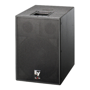
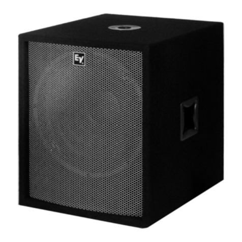
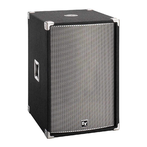
TheElectro-VoiceT18isa400-wattsubwoofer
loudspeaker system which combines the at-
tributes of both horn-loaded and vented-box
designs.ItutilizestheuniqueSubScoopTMcabi-
net construction with a newly revised DL18MT
woofer, as used in the Manifold Technology®
concert systems. The design behaves like a
hornovermuchofitsrange,butwithoutthetime
delay and weight problems usually associated
with conventional designs. Vented-box prin-
ciplestakeoverforthelowestoctaveandassist
in producing exceptionally high levels of clean,
punchy bass from a subcompact box. The
reverse woofer orientation has been used to
optimize the rear chamber volume and de-
creasethe horn flarerate for extendedlow-end
performance.
The T18 can be used to augment the bass
performance of any Electro-Voice stage sys-
tem. (This may involve the use of appropriate
electronics and crossovers.) A 13/8-in. stand-
mount receptacle on the top surface of the T18
allows satellite speaker systems such as the
T52 and T22 to be used (see Figure 4).
USE IN MULTIPLES
The T18 may be used in multiples to increase
acoustic output. A 6-dB increase in maximum
acoustic output occurs when two speaker sys-
tems are placed side by side and paralleled,
yieldinga4-ohmload.Foroperationatvery-low
frequencies,thewoofercones“mutuallycouple,”
acting as one system with twice the effective
cone area and power-handling capacity of a
singlesystem.Increasingtheconeareadoubles
the efficiency, providing a 3-dB increase in
sound pressure level. The doubled power ca-
pacity provides the potential for an additional
3-dB gain in maximum acoustic output.
SPECIFICATIONS
Typical Axial Frequency Response (swept
one-third-octave pink noise, anechoic
environment, 4 volts at 10 feet, normalized
for 1 watt/1meter; see Figure 1):
45-250 Hz
Low-Frequency 3-dB-Down Point:
45 Hz
Usable Low-Frequency Limit
(10-dB-Down Point):
33 Hz
Half-Space Reference Efficiency:
6.0%
Long-Term Average Power-Handling
Capacity per ANSI/EIA RS-426-A 1980
(see Power-Handling Capacity section):
400 watts
Maximum Woofer Acoustic Output:
24 watts
Sensitivity (SPL at 1 meter, 1 watt input,
anechoic environment, band-limited pink
noise signal, 50 to 200 Hz):
99 dB
Dispersion Angle Included by 6-dB-Down
Points on Polar Responses:
Essentially omnidirectional
Distortion, 0.1 Full Power Input (see
Figure 2),
Second Harmonic,
100 Hz: –52 dB, 0.25%
Third Harmonic,
100 Hz: –44 dB, 0.63%
Transducer Complement:
DL18MT
Box Tuning Frequency:
38 Hz
Recommended Crossover Frequency:
250 Hz or below
Recommended Crossover Slope:
12 dB per octave
C
A
B
I
N
E
T
GROUND INDICATOR
1/4-IN. PHONE PLUG
1 – 1 +
OR
2 –
2 +
1 +
1 –
NL4FC
PIN DIAGRAM
BANANA PLUG
➝➝
➝➝
➝
INPUT TO
SPEAKERSYSTEM
➝➝
➝➝
➝
1 +
1 –
T18 SPECIFICATION GRAPHICS
FIGURE 1 — Axial Frequency Response
FIGURE 2 — Harmonic Distortion 0.1 Rated Power Input
(30 watts)
FIGURE 3 — Dimensions
FIGURE 4 — Using the T18 with a Satellite Speaker
System
FIGURE 5 — Two-Conductor Cable Configurations for T18 Subwoofer
Using Neutrik Speakon®NL4FC Four-Pin Connector
Mutual coupling occurs when the frequency is
such that the center-to-center distance be-
tween the two woofer manifolds is less than
about one-half wavelength. When the distance
is greater than one-half wavelength, as would
occuriftwoT18’swerewidelyspaced,thelevel
increase tends to be limited to the 3-dB power-
handling increase.
The woofer is connected using one of the
Neutrik Speakon®or 1/4-inch phone jacks
marked“input.”Electro-Voicerecommendsthe
Neutrik NL4MPR-V connector be used in most
high power situations. The 1/4-inch jacks are
theretoprovidealevelofbackwardcompatibil-
ity with lower-powered systems. A parallel
woofer can be connected using the other con-
nector. Care must be taken not to abuse the
amplifier by connecting impedances which are
too low.
CROSSOVERS AND AMPLIFIERS
To optimize performance, the T18 should be
used in conjunction with an active crossover
with a minimum slope of 12 dB per octave and
a crossover frequency in the range of 100 to
250 Hz. Due to the high efficiency of the T18,
lessamplifierinputisneededtoachieveagiven
sound output level. The high power-handling
capacityoftheT18permitstheuseofamplifiers
witharatingofupto800wattsrmsinto8 ohms.
SPEAKER PROTECTION
Wheninthevented-boxmode,theSubScoop,TM
like all other vented systems, experiences rap-
idly increasing cone excursion below the box-
tuning frequency. The acoustic output is also
decreasing rapidly; therefore, it is sensible to
protecttheT18andmaximizethepoweroutput
of the subwoofer by inserting an active 32-Hz
high-passfilterwithaslopeofatleast12dBper
octave into the circuit. Such subpassband fil-
ters are found in many commercially available
crossovers and equalizers including items
manufactured by Electro-Voice.
FREQUENCY RESPONSE
The T18’s axial frequency response was mea-
sured in Electro-Voice’s large anechoic cham-
ber at a distance of 3 meters (10 feet) with a
sweptsine-waveinput.Figure1hasbeenaver-
aged and corrected for 1 watt at 1 meter.
ENCLOSURE CONSTRUCTION
Intended to be used as a portable speaker
system, the T18 is ruggedly constructed of
3/4-inch void-free plywood. All joints are dado
cut, and the cabinet is finished with a densely-
woven, abuse-resistant carpet that is both at-
tractive and highly durable. A full-length steel
grille protects the woofer from damage. Large,
heavy-duty metal corner protectors, firmly se-
cured rubber feet, and recessed handles com-
pletethepicture,ensuringthattheT18speaker
system is ideally suited for a long and reliable
life on the road.
T18 CONNECTIONS
TheT18isequippedwithtwoparalleledNeutrik
Speakon®NL4MPR-Vconnectors,selectedfor
their ability to reliably deliver to the speaker
components the high currents delivered by
high-wattagepoweramplifiers.AnNL4FCmat-
ingconnectorissupplied. TheNL4FCisafour-
pin connector, and Figure 5 shows how the
usual two-conductor speaker cable should be
wired to pins 1+ and 1– of the connector. Two
typicalconnectorsatthepoweramplifierendof
thecableareshown:bananaand1/4-inchphone
plugs. (The banana plug provides the more
reliable connection.)
Note also that Neutrik Speakon®cables, con-
nectors and wiring accessories are available
from Pro Co Sound, Inc., and Whirlwind Music
Distributors, Inc. To find your local Pro Co,
Whirlwind or Neutrik dealer, contact:
Pro Co Sound, Inc.
135 E. Kalamazoo Ave.
Kalamazoo, MI 49007
616/388-9675
Whirlwind Music Distributors, Inc.
P.O. Box 1075
Rochester, NY 14603
716/663-8820
Neutrik USA, Inc.
195-S3 Lehigh Ave.
Lakewood, NJ 08701
908/901-9488
USE WITH SATELLITE
SPEAKER SYSTEMS
The 13/8-in. stand mount in the top surface of
theT18canbeusedwithanylengthofstandard
13/8-in. tube. Care should be taken to ensure
that the T18 is used on a flat and level surface.
Electro-Voice strongly recommends that the
top of the satellite speaker be no more than 8
feet (244 cm) above the ground and weigh no
more than 75 pounds (34 kg). It is the respon-
sibility of the user to ensure that the system is
safe and stable. Do not use where the system
can be easily knocked over.
SERVICE
In the unlikely event the T18 requires service,
thewoofercanbereplacedorservicedfromthe
front. A service data sheet is available from
Electro-Voice.
POWER-HANDLING TEST
Electro-Voice components and systems are
manufactured to exacting standards, ensuring
they will hold up, not only through the most
rigorousofpowertests,butalsothroughcontin-
ued use in arduous, real-life conditions. The
EIA Loudspeaker Power Rating Full Range
(ANSI/EIARS-426-A 1980)uses a noise spec-
trum which mimics typical music and tests the
thermalandmechanicalcapabilitiesofthecom-
ponents. Electro-Voice will support relevant
additionalstandardsasandwhentheybecome
available.Extreme,in-housepowertests,which
push the performance boundaries of the woof-
ers, are also performed and passed to ensure
years of trouble-free service.
Specifically, the T18 passes ANSI/EIA
RS-426-A 1980 with the following values:
RSR = 6.9 ohms (1.15 x RE)
PE(MAX) = 400 watts
Test voltage = 52.4 volts rms,
104.8 volts peak
The“peak”power-handlingcapacityofawoofer
is determined by the peak test voltage amount.
For the T18, a 104.8-volt peak test voltage
translates into 1,600-watts short-term peak
power-handlingcapacity.Thisistheequivalent
of four times the “average” power-handling
capacity,andisapeakthatcanbesustainedfor
only a few milliseconds. However, this sort of
short duration peak is very typical in speech
and music. Provided the amplifier can repro-
ducethesignalaccurately,withoutclipping,the
wooferwillalsoperformaccuratelyandreliably,
even at these levels.
ARCHITECTS’ AND ENGINEERS’
SPECIFICATIONS
The loudspeaker shall be a horn-loaded type.
Thelowfrequenciesshallbereproducedwitha
400-watt (ANSI/EIA RS-426-A 1980) DL18MT
46-cm (18-in.) woofer. The system will repro-
duce the frequencies from 33 to 250 Hz. The
system shall be capable of producing average
sound levels in excess of 126 dB in the long
term, and short-term peaks of 132 dB.
The enclosure shall be constructed of black,
carpeted, multilayer plywood and have a metal
grille which attaches with six screws. The di-
mensions shall be 83.3 cm (32.8 in.) tall, 63.0
cm (24.8 in.) wide and 60.9 cm (24.0 in.) deep.
The system shall weigh 49.4 kg (109 lb). Neu-
trik Speakon®and 1/4-inch jack connections
shall be provided.
A13/8-in.standmountcapableofsupporting75
pounds (34 kg) will be provided in the top
surface of the T18 enclosure.
The loudspeaker system shall be the Electro-
Voice T18 subwoofer.
UNIFORM LIMITED WARRANTY
Electro-Voiceproductsareguaranteedagainst
malfunctionduetodefectsinmaterialsorwork-
manship for a specified period, as noted in the
individualproduct-linestatement(s)below,orin
the individual product data sheet or owner’s
manual, beginning with the date of original
purchase.Ifsuchmalfunctionoccursduringthe
specifiedperiod, theproduct willbe repairedor
replaced (at our option) without charge. The
product will be returned to the customer pre-
paid. Exclusions and Limitations: The Lim-
ited Warranty does not apply to: (a) exterior
finish or appearance; (b) certain specific items
described in the individual product-line
statement(s)below, orin theindividual product
data sheet or owner’s manual; (c) malfunction
resulting from use or operation of the product
other than as specified in the product data
sheet or owner’s manual; (d) malfunction re-
sulting from misuse or abuse of the product; or
(e) malfunction occurring at any time after re-
pairshavebeenmadetotheproductbyanyone
otherthanElectro-Voiceoranyofitsauthorized
service representatives. Obtaining Warranty
Service: To obtain warranty service, a cus-
tomer must deliver the product, prepaid, to
Electro-Voice or any of its authorized service
representativestogetherwithproofofpurchase
of the product in the form of a bill of sale or
receipted invoice. A list of authorized service
ELECTRO-VOICE a MARK IV company 600 Cecil Street, Buchanan, Michigan 49107
MANUFACTURING PLANTS AT BUCHANAN, MI NEWPORT, TN SEVIERVILLE, TN OKLAHOMA CITY, OK GANANOQUE, ONT.
© Electro-Voice, Inc. 1994 Litho in U.S.A. Part Number 532352 — 9427
representativesis available fromElectro-Voice
at 600 Cecil Street, Buchanan, MI 49107 (616/
695-6831. Incidental and Consequential
DamagesExcluded:Productrepairorreplace-
ment and return to the customer are only rem-
edies provided to the customer. Electro-Voice
shall not be liable for any incidental or conse-
quential damages including, without limitation,
injury to persons or property or loss of use.
Some states do not allow the exclusion or
limitation of incidental or consequential dam-
ages so the above limitation or exclusion may
not apply to you. Other Rights: This warranty
gives you specific legal rights, and you may
also have other rights which vary from state to
state.
Electro-Voice Speakers and Speaker Sys-
tems are guaranteed against malfunction due
to defects in materials or workmanship for a
period of five (5) years from the date of original
purchase.TheLimitedWarrantydoesnotapply
to burned voice coils or malfunctions such as
coneand/orcoildamageresultingfromimprop-
erly designed enclosures. Electro-Voice active
electronics associated with the speaker sys-
tems are guaranteed for three (3) years from
thedateof original purchase.Additionaldetails
are included in the Uniform Limited Warranty
statement.
Service and repair address for this product:
Electro-Voice,Inc.,600CecilStreet,Buchanan,
Michigan 49107.
Specifications subject to change without no-
tice.

Other Electro-Voice Subwoofer manuals

Electro-Voice T180 User manual

Electro-Voice

Electro-Voice T180 User manual

Electro-Voice ELX200-18SP User manual

Electro-Voice

Electro-Voice ELX200-18SP User manual

Electro-Voice DL12X User manual

Electro-Voice

Electro-Voice DL12X User manual

Electro-Voice S188E User manual

Electro-Voice

Electro-Voice S188E User manual

Electro-Voice SbA750 User manual

Electro-Voice

Electro-Voice SbA750 User manual

Electro-Voice SH-1800 User manual

Electro-Voice

Electro-Voice SH-1800 User manual

Electro-Voice EVID-S10.1DW User manual

Electro-Voice

Electro-Voice EVID-S10.1DW User manual

Electro-Voice SbA750 User manual

Electro-Voice

Electro-Voice SbA750 User manual

Electro-Voice Xds User manual

Electro-Voice

Electro-Voice Xds User manual

Electro-Voice 12" Powered Subwoofer System EVID 12.1P User manual

Electro-Voice

Electro-Voice 12" Powered Subwoofer System EVID 12.1P User manual

Electro-Voice S-181 User manual

Electro-Voice

Electro-Voice S-181 User manual

Electro-Voice ETX-18SP User manual

Electro-Voice

Electro-Voice ETX-18SP User manual

Electro-Voice Force Sub User manual

Electro-Voice

Electro-Voice Force Sub User manual

Electro-Voice TL440M Matinee User manual

Electro-Voice

Electro-Voice TL440M Matinee User manual

Electro-Voice X-Array XCN User manual

Electro-Voice

Electro-Voice X-Array XCN User manual

Electro-Voice S18 User manual

Electro-Voice

Electro-Voice S18 User manual

Electro-Voice EVF-2151D User manual

Electro-Voice

Electro-Voice EVF-2151D User manual

Electro-Voice EVA-1151D User manual

Electro-Voice

Electro-Voice EVA-1151D User manual

Electro-Voice Sb 180 User manual

Electro-Voice

Electro-Voice Sb 180 User manual

Electro-Voice Plasma Plasma P2 User manual

Electro-Voice

Electro-Voice Plasma Plasma P2 User manual

Electro-Voice SbA760 User manual

Electro-Voice

Electro-Voice SbA760 User manual

Electro-Voice Xds User manual

Electro-Voice

Electro-Voice Xds User manual

Electro-Voice SB2A User manual

Electro-Voice

Electro-Voice SB2A User manual

Electro-Voice EVF-1121S-FG User manual

Electro-Voice

Electro-Voice EVF-1121S-FG User manual

Popular Subwoofer manuals by other brands

Rockford Fosgate Element ready M1 Series manual

Rockford Fosgate

Rockford Fosgate Element ready M1 Series manual

Velodyne 1000 user manual

Velodyne

Velodyne 1000 user manual

Axis XT1408A installation manual

Axis

Axis XT1408A installation manual

JL Audio Stealthbox SB-T-4RNR2/10W3v2 installation guide

JL Audio

JL Audio Stealthbox SB-T-4RNR2/10W3v2 installation guide

Massive BOOM 8 owner's manual

Massive

Massive BOOM 8 owner's manual

Boss Audio Systems Phantom P128DC user manual

Boss Audio Systems

Boss Audio Systems Phantom P128DC user manual

YORKVILLE YSS1 Service manual

YORKVILLE

YORKVILLE YSS1 Service manual

LEGRAND evoQ 5000 Instruction/installation sheet

LEGRAND

LEGRAND evoQ 5000 Instruction/installation sheet

Creative Sonic Carrier MF8235 user manual

Creative

Creative Sonic Carrier MF8235 user manual

PYLE Audio PYM1278 owner's manual

PYLE Audio

PYLE Audio PYM1278 owner's manual

Tannoy Revolution SUB1001 owner's manual

Tannoy

Tannoy Revolution SUB1001 owner's manual

Creative iRoar Rock manual

Creative

Creative iRoar Rock manual

Morel Signature Series AMP 250 user guide

Morel

Morel Signature Series AMP 250 user guide

Aaron SW-200 Diagram

Aaron

Aaron SW-200 Diagram

Velodyne CT-100 user manual

Velodyne

Velodyne CT-100 user manual

Kenwood SW-36HT Service manual

Kenwood

Kenwood SW-36HT Service manual

Acoustech Elite Series owner's manual

Acoustech

Acoustech Elite Series owner's manual

Samsung HW-K460 user manual

Samsung

Samsung HW-K460 user manual

manuals.online logo
manuals.online logoBrands
  • About & Mission
  • Contact us
  • Privacy Policy
  • Terms and Conditions

Copyright 2025 Manuals.Online. All Rights Reserved.