ElectroDacus DSSR20 User manual
1
user manual
user manual
v0.95
www.ElectroDacus.com
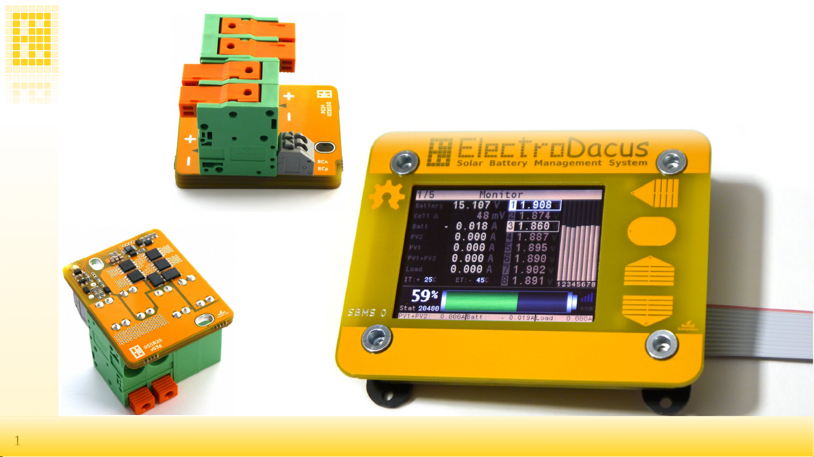
www.ElectroDacus.comSBMS0
SBMS0
SBMS0
DSSR20

2www.ElectroDacus.com
www.ElectroDacus.comSBMS40 / SBMS120
SBMS40 / SBMS120
Table of contents
Table of contents
Simplified diagram 3
Specifications 4
1. Install instructions 5
2. Thermal management 10
3. Cable selection 11
4. Mechanical installation 12
5. attery temperature 13
6. The 16pin connector 14
7. WiFi/US optional extension 15
8. Dual PV array functionality and SOC charge limiting
9. WiFi
16
17
10. Internal data logging 19
Schematic
22
Links to HW and SW files
43
11. User interface
46

3SBMS0
SBMS0
www.ElectroDacus.com
www.ElectroDacus.com
1
1
2
2
N
N
ADC1n / ADC1p
EXTIO3- / EXTIO3+
EXTIO4- / EXTIO4+
PVp / PVn
Pvn PVpADC1p ADC1n

4SBMS0
SBMS0
www.ElectroDacus.com
www.ElectroDacus.com
Specication
Specication
Battery type
Battery type any type of Lithium cells and Supercapacitors
any type of Lithium cells and Supercapacitors
Number of cells
Number of cells 3 to 8 cells
3 to 8 cells
Battery volta e limits (min/max)
Battery volta e limits (min/max) 8V to 32V
8V to 32V
Battery/PV recommandation 12V
Battery/PV recommandation 12V 4 cell LiFePO4 / 32 or 36 cells PV panel
4 cell LiFePO4 / 32 or 36 cells PV panel
Battery/PV recommandation 24V
Battery/PV recommandation 24V 8 cell LiFePO4 / 60 cells PV panels
8 cell LiFePO4 / 60 cells PV panels
Max PV Open Circuit volta e for DSSR20
Max PV Open Circuit volta e for DSSR20 49V (mono or polycrystalline panels with up to 72 cells)
49V (mono or polycrystalline panels with up to 72 cells)
PV input
PV input Usin as many DSSR20 as you want up to 30 or Victron MPPT with remote
Usin as many DSSR20 as you want up to 30 or Victron MPPT with remote
DSSR20 PV current
DSSR20 PV current
20A so up to two lar e 60 or 72 cell panels
20A so up to two lar e 60 or 72 cell panels
External PV current shunt
External PV current shunt 10A up to 750A
10A up to 750A
External Batt current shunt
External Batt current shunt 10A up to 750A this is required for SOC calculation so it needs to be installed
10A up to 750A this is required for SOC calculation so it needs to be installed
EXT IOx optoisolators
EXT IOx optoisolators TLP187 max 300V 150mA
TLP187 max 300V 150mA
Cell balancin current
Cell balancin current max 200mA
max 200mA
Power terminal max wire size DSSR20
Power terminal max wire size DSSR20 AWG #10 (6mm2) should be reat for two panels, connectors max AWG #6 (16mm2)
AWG #10 (6mm2) should be reat for two panels, connectors max AWG #6 (16mm2)
Battery temperature sensor
Battery temperature sensor Thermistor (optional) 10KOhm B3900
Thermistor (optional) 10KOhm B3900
16pin connector / ( 8pin + 2pin ) side connector
16pin connector / ( 8pin + 2pin ) side connector Includes I2C, UART, Ext IO, 16bit ADC / ext current shunt for Battery and PV
Includes I2C, UART, Ext IO, 16bit ADC / ext current shunt for Battery and PV
Data lo in to internal Flash memory
Data lo in to internal Flash memory 128Mbit (16Mbyte) 2 minute interval for one year of data
128Mbit (16Mbyte) 2 minute interval for one year of data
WiFi plus di ital isolation and UART to USB
WiFi plus di ital isolation and UART to USB WiFi used for remote monitorin ( SBMS acts as AP ) USB for lo data download
WiFi used for remote monitorin ( SBMS acts as AP ) USB for lo data download
Display
Display SBMS0 2.4” ( Color LCD 320x240 )
SBMS0 2.4” ( Color LCD 320x240 )
Wei ht
Wei ht SBMS0 ~150 / DSSR20 ~70
SBMS0 ~150 / DSSR20 ~70
Dimensions
Dimensions 90mm x 70mm x 26mm
90mm x 70mm x 26mm
Self consumption
Self consumption 300mW to 800mW (WiFi and Backli ht ON)
300mW to 800mW (WiFi and Backli ht ON)
Max TDP
Max TDP SBMS0 (3W) / DSSR20 (1.4W)
SBMS0 (3W) / DSSR20 (1.4W)

5SBMS0
SBMS0
www.ElectroDacus.com
www.ElectroDacus.com
1 Install Instructions
1 Install Instructions
Step 1
Step 1
Connect the included 12 wire cell monitoring/balancing cable to your battery pack. Number 12 wire is the one marked with red.
Any number of parallel cells are no different from a single higher capacity cell so if you have multiple small cells you will need to form first groups
of parallel cells then connect those groups in series for needed voltage. LiFePO4 is the most cost effective battery at the end of 2019 and a 4s with
that will make a 12V battery and a 8s will make a 24V battery.
All configurations from 3s to 8s are shown below. The corresponding wire number is marked with dark gray color (all wires are used).
3
3
5
5
7
71
1
4
4
6
6
8
82
2
3
3
7
71
1
4
4
6
6
8
82
2
3
3
7
71
1
6
6
8
82
2
3
3
7
71
1
8
82
2
7
71
1
8
82
2
1
1
2
2
8
8
1+2
3
4
5
6
7
8
9
10+11+12
4+5+6+7+8+9
1+2
3
4
5
6+7
8
9
10+11+12
1+2
3
4
5+6+7+8
9
10+11+12
1+2
3
4
5+6+7
9
10+11+12
8
1+2
3
10+11+12
4+5+6+7+8
1+2
3
10+11+12
9
5s
5s
7s
7s
3s
3s 4s
4s
6s
6s
8s
8s

6SBMS0
SBMS0
www.ElectroDacus.com
www.ElectroDacus.com
Step 2
Step 2
Go to Parameter Settings menu and select the type of cell, number of cells and battery capacity then push Store Parameters button to save data to
S MS. Then remove the 12pin connector and reconnect for the new stored parameters to be accepted.
Step 3
Step 3
You can now remove the 12pin connector and start working on the 8 + 2 pin side connector.
A CAT5 or CAT6 type cable is ideal there as you have 4 pairs of twisted wires and can use one for attery current shunt (ADC1n/ADC1p) then
second one for PV current shunt (Pvn/Pvp) the third one for EXT IO3 (EXTIO3+/EXTIO3-) and last one for EXT IO4 (EXTIO4+/EXTIO4-).
See diagram on page 3 for details and you can even respect the color scheme that I used :) as usually the CAT cables have those colors
rown,Orange, lue and Green.
The XT1+/XT1- is optional but if you want you can connect a battery temperature sensor that will be a 10KOhm Thermistor search for “10KOhm
3950 NTC” and you can find many options and also use a twisted wire pair for this.
All you need to do is strip 4 to 5 mm from the end of the wire and insert in the connector until the stop is reached. To remove the wires
or insert stranded wire insert a needle in the corresponding rectangular hole above the wire as seen in the third drawing below.
secure the cable to the S MS0 or to the front panel the S MS0 is mounted on.
*Screenshots for 4s the diagram on the bottom will
change to reflect the correct connection for different
configurations you select but see the anterior page for
details on all available configurations from 3s to 8s.
Any number of parallel cells are no different from a
single higher capacity cell as all parallel cells will
have the exact same voltage.
7SBMS0
SBMS0
www.ElectroDacus.com
www.ElectroDacus.com
Step 4
Step 4
Since the CAT5 or CAT6 cable is connected to the S MS0 you can connect the current shunt's.
The attery current shunt is mandatory as it is needed to calculate the battery SOC (State of Charge) and gets connected to attery+ terminal on
one side then on the other side to a fuse or circuit breaker and your Load and chargers.
The PV current shunt will be great to have as it will provide way more info as with just the battery current shunt mentioned above all you see is
battery current and you have no idea of how much the load uses or how much the PV array is producing.
Example: Say you have a 50A load and 30A coming from your PV array then the battery current shunt will see 20A getting out of the battery and
that is only useful to calculate how much energy gets out of the battery and calculate the SOC but you know nothing else.
y adding the PV current shunt now you measure those 30A and so if you add that to 20A getting out of the battery you can calculate the Load and
get the 50A load uses thus you know with two current shunts know all the data and S MS0 can display that for user and calculate the total energy
coming from PV, the energy used by the Load and how much the battery was involved in all this so unless you want to save a few $ I highly
recommend having both current shunt's installed.
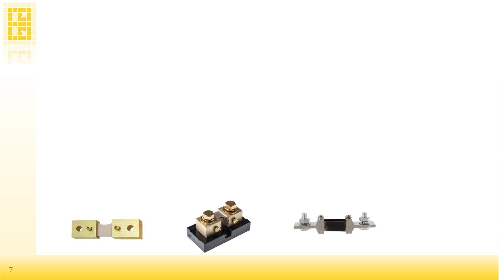
Current shunts are nothing more than a power resistor and they may be spec as a max current they can handle and the voltage drop at that current
like say 100A 75mV or as a resistance value and a power rating for the resistor so 0.075V/100A = 0.00075Ohm or 0.7500mOhm (this will be the
number you set in the S MS0) and a power rating 100A x 0.075V = 7.5W
The ADC1n/ADC1p input can read in the -90mV to +90mV range so can read current in both directions while the PVp/PVn current shunt can read
current in a single direction 0V to +90mV thus to best take advantage of this range a 75mV current shunt can be used but 50mV current shunts and
100mV current shunts will also work.
You will want to select a current shunt so that your max continues current is no more than 66% of the shunt rating. As an example if you expect a
2000W max continues load from your 24V battery then 2000W/24V = 83.33A and thus a 100A current shunt will get to hot and you will want a
150A or 200A current shunt. You will also not want to jump to a 500A or 1000A current shunt in this example as then your resolution when you
measure small current will not be that great.

8SBMS0
SBMS0
www.ElectroDacus.com
www.ElectroDacus.com
Step 5
Step 5
Connect the EXT IO3 set as type 2 to your inverter, large DC/DC converter or for multiple small DC loads to Victron attery Protect or similar
device. Most of you will use an inverter and the inverter will need to support remote ON/OFF and while a lot of them do not all can support that.
Simple rule will be that any inverter with a mechanical single pole single trow ON/OFF switch will be able to support remote ON/OFF compatible
with S MS0 but you may need to solder two wires in parallel with that ON/OFF switch if there is no remote port available on the unit.
Inverters that have a momentary type ON/OFF switch most likely will not support compatible remote ON/OFF but there are a few exceptions.
To test set the EXT IO3 as type 0 and inverter should turn OFF then you can set back on type 2
ellow is just a short list of inverters compatible with S MS0 but way more than this presented here will work.
I think ll Victron inverts re comp tible.
Pheonix, Multiplus, Qu tro
Pheonix 12/500 (~$180)
Pheonix 24/1200 (~$400)
Multiplus 24/3000/70 (~$1300)
BP65 for sm ll DC lo ds (~$40)
The Victron multiplus inverter/ch rge m y
be the only one with sep r te remote for
inverter nd ch rge.
Most Cotek inverts re comp tible.
COTEK SP1000 (~$350)
COTEK SP2000 (~$640)
COTEK SP3000 (~$960)
COTEK SP4000 (~$1280)
Some other inverts th t re comp tible not
sure if spec re re l.
Ronegy 3000W (~$370)
PIP2424HSE - 220V (~$250)
PIP2424HSE c n be used s inverter only
not ch rger nd it is 220V only, the 120V
version is much more expensive.

9SBMS0
SBMS0
www.ElectroDacus.com
www.ElectroDacus.com
Step 6
Step 6
Connect the EXT IO4 set as type 1 to your charger and that can be the DSSR20 (multiple of them up to 20 no problem and up to 30 if using two
EXT IOx ports) an MPPT solar charger that has remote ON/OFF support as some Victron Smart solar or lue Solar with the adittion of a $20
remote ON/OFF cable or a grid charger that has remote ON/OFF like the RSP-750-15 for 12V battery or RSP-750-27 for 24V battery.
A few battery to battery charger also have remote ON/OFF and can be used but charging from vehicle alternator is 50x more expensive than form
PV so it should be avoided if cost is important to you.
To test set EXT IO4 as type 0 and charging should stop then you can set back as type 1
ellow is just a short list of chargers compatible with S MS0 but way more than this presented here will work.
Electrod cus DSSR20.
This is sure the most cost effective option
for PV sol r ch rging nd llows PV rr ys
from 100W up to 18kW
PV needs to m tch b ttery volt ge so 32
or 36 cells for 12V b ttery nd 60 or 72 cell
PV for 24V b ttery.
DSSR20 (~$27)
Victron MPPT Sol r ch rgers with remote.
BlueSol r 100/20 + remote (~$160 + $20)
Sm rtSol r 150/85-TR (~$680)
Other type of ch rgers.
Ronegy 40A b ttery to b ttery (~$200)
( ltern tor >$1/kWh not recommended).
RSP-750-15 grid ch rger (~$180)
(grid ~$0.2/kWh)
Or +

10 SBMS0
SBMS0
www.ElectroDacus.com
www.ElectroDacus.com
2 Thermal Mana ement
2 Thermal Mana ement
The S MS0 and DSSR20 are passively cooled and do not require any heat-sink or active cooling.
DSSR20 has a total of 3.5mΩ internal resistance
So at 20A TDP = 20A x 20A x 0,0035Ω = 1.4W
With 60 cell panels 27V x 20A = 540W and with 1.4W loss it will be a 99.7% transfer efficiency.

11 SBMS0
SBMS0
www.ElectroDacus.com
www.ElectroDacus.com
3 Cable Selection
3 Cable Selection
For DSSR20 ideal and most cost effective is 6mm2 (AWG #10) PV cable for roups of two parallel panels. The two panels can be 60 cell panels
for 24V battery so 250 to 320W dependin on panel efficiency and if panels are very far like more than 20m (60ft) then you may consider
oin with 72 cell panels as then you can accept hi her volta e drop and can sue this same cable up to 60m (200ft).
With 32 cell panels for 12V batter keep the distance below 20m (60ft) with same 6mm2 (AWG #10) for two parallel panels if made with
156mmx156mm (6x6”) cells usually rated 160 to 180W dependin on cell efficiency or you can use up to 3 panels in parallel if panels are
made with 32 or 36 cells in series that are 125mmx125mm (5x5”).
With SBMS0 a 1.8m (6ft) ribbon cable is provided and is best to keep it to this max limit or you can cut the cable shorter. For the 10pin side
connector ideal is a CAT5 or CAT6 type cable as that will have 4 pairs of twisted wires and you can use one for each of say ext current shunt,
ext PV current shunt, EXT IO3 and EXT IO4. If you also want to measure the battery temperature (will likely just be the same as ambient as
in this applications battery is char ed with at most 0.2C and dischar ed at 0.5C in avera e and that is nothin especially for LiFePO4 that I
stron ly recommend as they are still the best most cost effective option for off rid ener y stora e) then just use a pair of twisted wires maybe
et that from another CAT5 or CAT6 cable.

12 SBMS0
SBMS0
www.ElectroDacus.com
www.ElectroDacus.com
4 Mechanical installation.
4 Mechanical installation.
S MS0 is designed for front panel mount see photos below for an example. Yes I used a piece of cardboard from the last mouser shipping but you
will of course not use that :) and this is just to show how it should be installed.
Unscrew the 4 screws (T10) just enough to be able to slide the two black
PC 's and this will allow you to slide the S MS in the front panel cutout.
*Slide the PC 's back in to position and tighten them.
The blue a purple wires are soldered to ADC2 & ADC3 that can read 0 to
60VDC and was for testing not much use at this time.
Get the 4 nylon bolts and 8 nylon nuts included and install them in the 4
corners as illustrated.
Nothing to say here other than front panel needs to be less than 3mm thick
and that it looks great even on cardboard :).

13 SBMS0
SBMS0
www.ElectroDacus.com
www.ElectroDacus.com
5 Battery Temperature
5 Battery Temperature
It is possible to add external temperature sensor but in most cases not needed and so is optional.
All Lithium batteries require temperature above freezin (> +5°C) durin char in otherwise they will be dama ed.
est way when possible is to have the battery inside the living space were temperature is ideal for battery operation.
The S MS is designed to accept a thermistor as temperature sensor connected between pin 3 (XT1-) and 4 (XT1+) of the 8 pin connector.
The S MS is calibrated for a particular 10kΩ thermistor made by Murata NCP21XV103J03RA (this same thermistor type is used internally to
measure the power board temperature) but a common 10kΩ NTC with 25/50 = 3900 to 3950 will work great.
The low and high temperature limits for this external temperature sensor can be set from the Advanced Parameter Setting submenu parameter 29
and 30.
Value is a 12bit binary number and if you use the recommended thermistor the 0°C=3144b,+5°C=3000b, +50°C=1338b,+55°C=1182b,
+60°C=1040b.
You can see the actual temperature in Monitoring menu and the raw binary value in Diagnostic menu.

14 SBMS0
SBMS0
www.ElectroDacus.com
www.ElectroDacus.com
6 The 16pin connector
6 The 16pin connector
There is a 16pin connector on the left side of the LCD on S MS and it is used for different functionality described below.
01 02
03 04
05 06
07 08
09 10
11 12
13 14
15 16
USART TX USART RX
SDA / EXT IO1
BOOT 0
ESP RST
GND
3.3V 2.7V)
EXT ADC2
GND
EXT IO2 / SCL
EXT IO5 / SWK
EXT IO6 / SWD
GND
3.3V 2.7V)
EXT ADC3
GND
01 & 02 UART TX and RX pins are used for the WiFi module so if you want to use the USART for
something else then WiFi will be disabled (voltage levels 0 to 3.3V).
03 & 04 This two pins are reserved as I2C port for communicating with Digital MPPT heat
controller. Firmware version 3.0g or higher has support for DMPPT450 but only for
monitoring and settings with S MS0 not charging.
05 oot 0 connected to pin 12 will put the STM32F373 microcontroller in programming mode.
06 & 08 This pins have dual function as programmable EXT IO5 and IO6 (0 to 3.3V 20mA max)
and as SWK and SWD programming interface for the STM32F373.
07 ESP Flash connected to GND will put the ESP32 WiFi module in programming mode.
12 This is a 3.3V (3.15V typical) supply from the main board after it will go trough a schottky
diode will supply the WiFi module drooping to around 2.7V or if WiFi is OFF 2.8V that will
supply the digital isolator.
13 & 14 Ext ADC inputs 2 and 3 with analog input range of 0 to 1.8V that will be logged in the internal S MS memory at 2 minute
intervals but not used in any automation with the latest firmware version. This are good if you want to log some other analog signals.
09, 10, 15 & 16 GND (same common ground plane for all 3 pins).

15 SBMS0
SBMS0
www.ElectroDacus.com
www.ElectroDacus.com
7 WiFi/USB optional extension
7 WiFi/USB optional extension
There PC board below is the back cover of the S MS0 but not populated with components unless you select the extra WiFi/US option.
WiFi/USB option l c rd.
On the left side in the photo there is micro USB connector th t is then
connected to USB to UART converter the 10pin IC nd then it will go to
the MAX14851 the 16pin IC nd this is high speed digit l isol tor so
everything on this side of th t long nd n rrow cut is g lv nic isol ted from
SBMS0 including the USB, UART, I2C nd the to EXT IO5 nd IO6
isol ted by the two Toshib TLP187 bove the digit l isol tor.
On the other side of the isol tion you h ve the ESP32 WiFi module nd
you lso h ve two ADC inputs set with the two precision resistors
134kOhm nd 3.9KOhm nd this c n me sure 0 to 60V s referenced to
B ttery neg tive. There is no speci l function for this two ADC t the
moment but the v lues will be logged in the intern l SBMS fl sh memory
th t will log ll d t t 2 minutes interv l for one full ye r.
There is 16pin Molex connector th t is not soldered in this photo nd th t
is how this bo rd will connect to the SBMS0 m in bo rd.
Since the UART nd USB re fully isol ted you c n connect without
problems ny computer or R spberry Pi type bo rd even if those re
supplied from s me b ttery.
There is sp ce for 10pin connector (will be included but not soldered)
nd on those (l beled on the other side) you h ve ccess to I2C, UART
nd the EXT IO5, EXT IO6 ll of them g lv nic isol ted from SBMS0.
If you re using the USB then this side of the isol tor is powered from USB
else if you s y w nt to use this with UART directly connected to R spberry
Pi or simil r bo rds then you need to provide lso 3.3V on the 3V l beled
pin.
16 SBMS0
SBMS0
www.ElectroDacus.com
www.ElectroDacus.com
8 Dual PV array functionality and SOC char e limitin
8 Dual PV array functionality and SOC char e limitin
S MS0 has now to of the DMPPT450 functionalities see below the details.
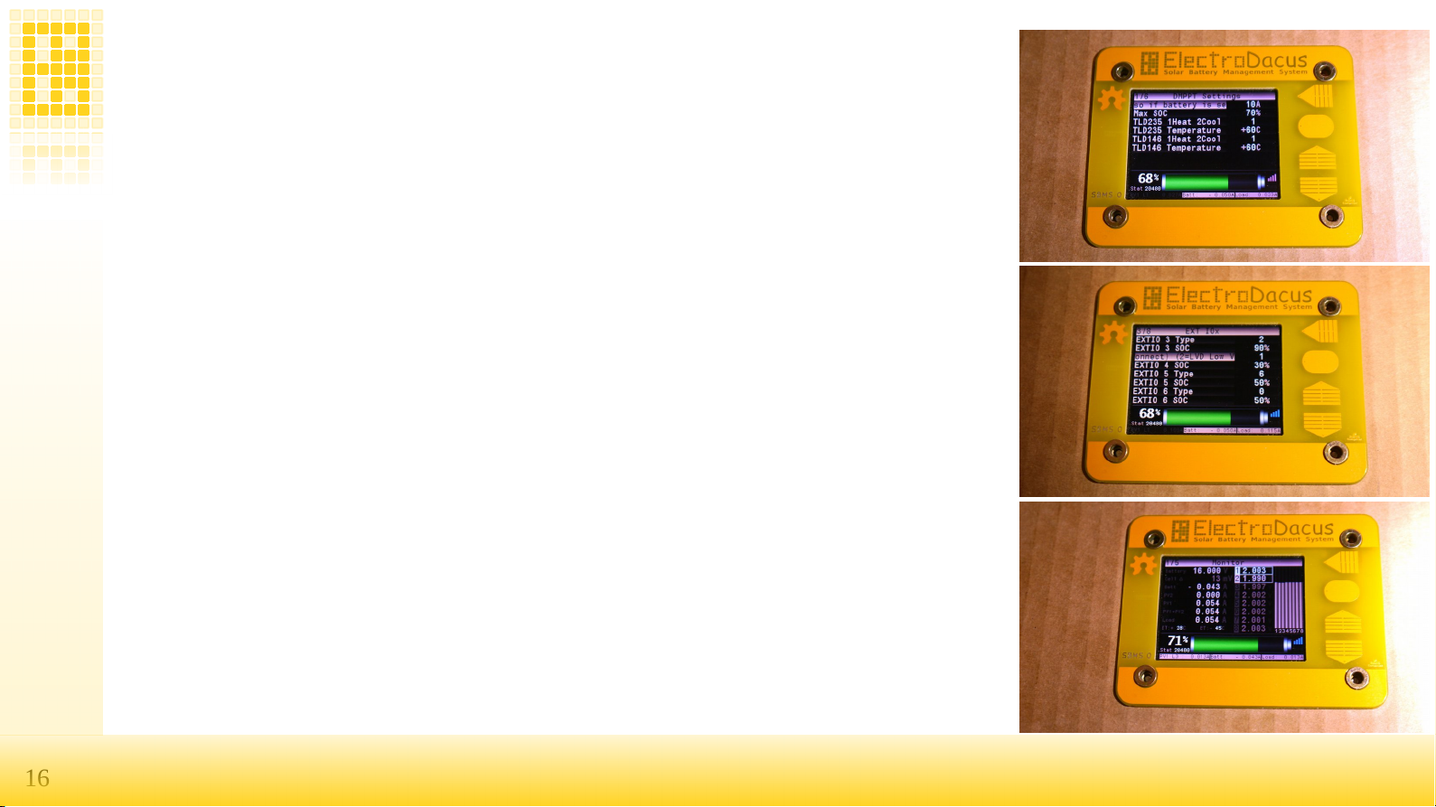
In the first photo you c n see the s me two DMPPT450 settings m x ch rge current nd M x SOC lso
pply now to SBMS0 directly.
The m x SOC limit is in this ex mple set t 70% nd wh t will h ppen is th t every new d y the b ttery will
first be fully ch rged 100% SOC but then the next ch rge cycles for the s me d y will only st rt t 67% nd
end t 70% so it will st y round 70% SOC nd cycle there with 3% SOC hysteresis. You c n set this t
ny limit 80 to 90% will be gre t setting for LiFePO4 while for NMC nd LiCoO2 round 70% to 80% will be
best.
The m x ch rge current c n be set between 10A minimum nd 600A m x for SBMS0 s one typic l 60 cell
p nel outputs up to 10A nd you c n not h ve less th n one p nel nd SBMS0 c n support 60 of those
p nels with the use of 30x DSSR20's
The w y this limit works is th t you will h ve the PV rr y split in two with sm ll PV rr y set s type 1 nd
second rr y ide lly 2x the size of the first s type 6.
In second photo you see EXT IO4 set s type 1 nd EXT IO5 s type 6.
As n ex mple 24V 200Ah LiFePO4 b ttery should be ch rged t m x 50 to 60A so you c n just use 6
l rge p nels nd th t is ll but since p nels re less expensive th n b tteries it is useful to h ve l rger PV
rr y nd so you c n dd second sep r tely controlled rr y of 12 p nels th t is controlled by EXT IO5
set s type 6 nd this w y when the sm ll 6 p nel rr y only outputs h lf the 50A limit s y 24.99A the
SBMS0 will disconnect this nd switch the 12 p nel rr y th t if in s me conditions should now output
round 50A so even if mount of sol r dropped to h lf you c n still ch rge t full 50A this will be c lled level
2 noted with L2 on the LCD nd if this drops below 66% of 50A = 33A then it will dd the 6 p nels t the
s me time so now you h ve ll 18 p nels connected nd should still get 50A this will be c lled level 3 you
c n see in l st im ge the L3 indic tion on the lower left p rt of the screen just fter PV1.
If now the sol r incre se to more th n 20% bove the 50A limit (60A) then it will drop to Level 2 nd if th t
lso exceeds by 20% the m x setting it will drop to Level 1 th t since only h s 6 p nels c n not exceed the
ide l ch rge current for this b ttery.

17 SBMS0
SBMS0 www.ElectroDacus.com
www.ElectroDacus.com
9 WiFi
9 WiFi
S MS0 include an optional WiFi module that can be used for remote monitoring. The S MS acts as an AP (Access Point) and will deliver data to a
WiFi enabled computing device that supports a HTML5 capable web browser (a smart phone, tablet or laptop/desktop computer).
All you need to do is download and decompress this html file http://electrodacus.com/S MS120/SW/S MS.zip and copy to your device then
connect to S MS-000 named AP and open that file with your preferred web browser.
Notice cell balancing on cell number 5. I had not captured cell balancing in the other photos since cells are well balanced. The “<
<” symbol after
cell voltage indicated cell balancing is performed on that cell.
*Photo shows the older S MS100 but it works the same in this regards.

18 SBMS0
SBMS0
www.ElectroDacus.com
www.ElectroDacus.com
The raw data over WiFi are transmitted in a compressed format and if you want to see the raw data you can just write in your web browser address
window the following IP address while connected to S MS 192.168.4.1 then you will see something similar as below.
var PV1="################################################################################################################################################################################################################################################";
var PV2="###################################################################################A\\_ky}vnM#L$##@*###=###D###L$###I2#-;}xtqp ######################MnoqpoligU############:VUUTSSRQP||||||||||||{|||||{||{||||||||||||||{||{{{{||||{{{{|{|{{|||{";
var Btp="###################################################################################?X\\iy}vmI#G###9#### ###?###H####<$##4}vqoo'######################0Y[\\\\ZWTR<#############<<GJIHHFFx}vuvwvvwwww{|{|vu{tu|uvwwvvvuv{zvutyzttuvw{uuttt{uwvvvvwvvu";
var Btn="############################################################################################,#*,,##,,,#,,,#,,,#*,,,##3(####### 7 77 77777778:##########GGGGGGGGGGHH*#####################################################################";
var Ld ="%$$$$$$$%$%$$$$$%%%%%%%$$$$%$%$%$%%%$$$$$$$$$%$%&&&&&%%&%&&&%%&&&&%&%%&'(''''&%%&%&>QRSSRRQQTSUTUSTUUUSTTTRTTTPRSTW|z}|UOOPNMQRQQRRRRSRSSSRSTTTSTTUZ}{z{{zzyxxzzz{{{{|{{||zzz^TSSQSRvly{yxxzwwwxnnomxzn|zmzzvwyzyzypryz}rp|
zywuo{z{zznywwxvwwxxz";
var ELd="################################################################################################################################################################################################################################################";
var sbms="3';2LD$,I)I*I+I+H}I%I+I**h##+#)P####->##################%N(";
var xsbms="#&lL >N$##5";
var gsbms="#Kc#7?#-L#Hp#*+#)r#)|#&|";
var eA="####.(##########K2empty-####K2####3i######";
var eW="####&%##########-xempty-####-x####'X######";
var s1=['Ah','A','SBMS100'];
var s2=[0,0,0,0,0,0,0,0,3,5,1,1];
The small print above is an example of what you will get if you look at the raw data. The data is compressed using my proprietary base 91
encoding using the ascii characters from 35 "#" to 125 "}" this was a simple and efficient way for me to compress data.
The first 6 variables in that raw data are the data for displaying the 6 graphs (3 graphs windows each containing 2 graphs or in the case of battery
a separate graphs for charging and discharging)
It will be simple to deduce each of those variables and what they contain by looking at the java script code inside the html file mentioned above.
Since this are just raw data representing measurements made by the S MS you can modify the html page so that you can get a better / nicer user
interface or more tailored to your needs.
The sbms variable is the one containing the most important data and I will go in to more details about that one in the next chapter related to S MS
internal data logging.

19 SBMS0
SBMS0 www.ElectroDacus.com
www.ElectroDacus.com
10 Internal data lo in
10 Internal data lo in
The S MS has an internal 128Mbit (16Mbyte) SPI Flash memory that can log data at a fixed 2 minute interval.
The memory is capable of storing a full year (12months) of data in a circular type buffer so you always have the last 12 months worth of data in
that internal Flash memory.
In order for the data logging to start you will need to set the Date and Time and you will notice the small “mem” symbol in the lower right side of
the S MS LCD being highlighted.
The data is also stored compressed in the memory same base 91 compression mentioned in the WiFi chapter and contains the data sent also over
WiFi in the sbms variable.
Here is an explanation of what is contained there and what it is logged in the internal memory.
var sbms="YMDHMS%%C1C2C3C4C5C6C7C8ITET+ ATPV1PV2EXTAD2AD3AD4ht1ht2ERR"
Y-year last two digit (limited to 2090); ( sorry if you read this in 2091 I will not expect a software update :) ).
M-month
D-day
H-hour
M-minute
S-seconds
%% - SOC 0 to 100%
C1 to C8 - cell voltage in mV
IT and ET - internal and external temperature in hundreds of a degree 0 is -45C and 1449 is 99.9C so you need to subtract 450 from the result and
divide by 10 (example 689 as result of the decompression will be (689-450)/10=23.9C)
+ - sign for battery charging (+) and discharging (-) used as it is no compression.
AT - attery current in mA from -750000mA to +150000mA
PV1 - PV1 input current in mA
PV2 - PV2 input current in mA

20 SBMS0
SBMS0 www.ElectroDacus.com
www.ElectroDacus.com
EXT - Ext Load current (the use of 10A up to 500A 75mV external current shunt is possible on both S MS40 and S MS120 see page 13)
AD2 and AD3 - user available ADC inputs the value is the digital output of the ADC.
ht1, ht2 - reserved for power output of the DMPPT450
ERR - this is error code it will contain the information referring to the error flags on the S MS.
There are 15 Flags (see monitoring page3 on S MS) not all flags represent an error some are representing normal operation and if you consider
this a 15bit binary number each bit representing one flag with “1” highlighted and “0” not highlighted and you start from the top left with OV flag
and continue to right and then down to the last flag DFET and consider the OV as the least significant bit and DFET most significant bit then you
get this binary number and convert to decimal that will be the value contained in this ERR Status and you can also see this number on the S MS
LCD just under the battery SOC value and also displayed as Status: in the html page.
Uncompressed data and formatted in .csv as it was on S MS4080 will look like this
Y ,M ,D ,H ,M ,S ,SOC,cel1 ,cel2 ,cel3 ,cel4 ,cel5 ,cel6 ,cel7 ,cel8 ,IT ,ET ,- att , PV1 , PV2 ,ExtLoad, ADC2, ADC3, ADC4, heat1 , heat2 , ERR
00,01,31,22,53,47,100,3414,3416,3444,3433,3426,3419,3420,3380,000,000,-002000,000000,000000,000000,000000,000000,000000,000000,000000,000000
This is the javascript function for decompression (you will find this inside the S MS webpage) function dcmp(p,s,d){xx=0; for (z=0;z<s;z++){xx =
xx + ((d.charCodeAt((p+s-1)-z)-35)*Math.pow(91,z));}return xx;}
Were
p - location of the data in the string.
s - size of the data (example year is 1 cell voltage is 2 and PV1 current is 3)
d - the name of the variable in this case sbms.
This manual suits for next models
3
Table of contents
Popular Inverter manuals by other brands


Green Power
Green Power 600G Installation instructions & user manual

Sun Power
Sun Power SPR-5000m installation guide

Power Drive
Power Drive PD2000 owner's guide

Power Drive
Power Drive PD120 owner's guide

Power Stroke
Power Stroke PS906025P series Operator's manual

Kaco
Kaco blueplanet gridsave 92.0 TL3-S quick guide