KICK ASS KAI700WPD User manual

PURE SINE WAVE
DIGITAL INVERTER
USER MANUAL
V1.2
K A I 7 0 0 W P D | K A I 1 2 0 0 W P D | K A I 2 0 0 0 W P D | K A I 3 0 0 0 W P D

2. IMPORTANT SAFETY INFORMATION
Warning
Before installing and using this inverter, read and follow the safety information below.
2-1 General safety precautions
2-1-1. Do not expose the inverter to rain, snow, spray, water, bilge or dust.
To reduce risk of hazard, do not cover or obstruct the ventilation openings.
Do not install the inverter in a zero-clearance compartment, this may result in overheating.
2-1-2. To avoid a risk of fire and electronic shock make sure that existing wiring is in good electrical
condition; and that wire size is not undersized. Do not operate the inverter with damaged or
substandard wiring.
2-1-3. This equipment contains components which can produce arcs or sparks. To prevent fire or
explosion, do not install in compartments containing batteries or flammable materials or in
locations that require ignition protected equipment, this includes any space containing gasoline-
powered machinery, fuel tanks, or joints, fittings, or other connection between components of the
fuel system.
1. INTRODUCTION
Thank you for purchasing a KickAss Pure Sine Wave Digital Inverter. This unit converts 12V DC to
240V AC using intelligent electronics, so you can operate and run mains powered devices from a
suitable sized 12V battery. As inverters output hazardous voltages, please ensure all instructions
are read carefully before use.

32,0
261,8
270,6
284,1
5,2
7,0
150,0
78,6
700W Pure Sine Wave Inverter
4. DIMENSIONS AND SPECIFICATIONS
3. FEATURES
KAI700WPD
• Highly efficient pure sine wave AC output
• Digital controller with LCD Screen
• Remote digital controller with LCD Screen (Accessory)
• USB charging port 5V 2.1A
• User selectable voltage cut outs
• AC/DC isolated design
• Smart cooling design
• Capable of driving inductive and capacitive loads
• Protection features including, low voltage alarm, overload shutdown, short circuit, input
overvoltage and over temperature
KAI700WPD
12V
10-15V DC
≦1A
≧90%
10mm²
240V AC 50/60Hz±0.5Hz
700W
1400W
5V 2.1A
Pure Sine Wave
5m
SKU
DC Volt
Input Voltage Range
No-Load Current
Convert Efficiency
DC Wiring
Output Voltage
Rated Power
Peak Power
USB
Waveform
Remote Cord Length

110,0
340,3
362,3
113,3
8,8
15,2
245,0
1200W Pure Sine Wave Inverter
KAI1200WPD
KAI1200WPD
12V
10-15V DC
≦1A
≧90%
16mm²
240V AC 50/60Hz±0.5Hz
1200W
2400W
5V 2.1A
Pure Sine Wave
5m
SKU
DC Volt
Input Voltage Range
No-Load Current
Convert Efficiency
DC Wiring
Output Voltage
Rated Power
Peak Power
USB
Waveform
Remote Cord Length
110,0
400,3
422,3
113,3
8,8
15,2
245,0
2000W Pure Sine Wave Inverter
KAI2000WPD
KAI2000WPD
12V
10-15V DC
≦1A
≧90%
25mm²
240V AC 50/60Hz±0.5Hz
2000W
4000W
5V 2.1A
Pure Sine Wave
5m
SKU
DC Volt
Input Voltage Range
No-Load Current
Convert Efficiency
DC Wiring
Output Voltage
Rated Power
Peak Power
USB
Waveform
Remote Cord Length

KAI3000WPD
12V
10-15V DC
≦1A
≧90%
35mm²
240V AC 50/60Hz±0.5Hz
3000W
6000W
5V 2.1A
Pure Sine Wave
5m
SKU
DC Volt
Input Voltage Range
No-Load Current
Convert Efficiency
DC Wiring
Output Voltage
Rated Power
Peak Power
USB
Waveform
Remote Cord Length
5. INSTALLATION
The inverter has four slots in its mounting bracket that allow the unit to be fastened against a
bulkhead, floor, wall or other flat surface. Ideally, the mounting surface should be cool to the touch.
To avoid voltage drop install inverter as close as possible to the 12V DC power source (Battery).
The inverter can be operated in any position, however, if it is to be mounted on a wall, mount it
horizontally so that indicators, switches, outlets and terminal blocks located on the front panel are
visible and accessible. If the inverter is to be installed in a moving vehicle, we strongly recommend
that the inverter be shock-mounted either on the floor (in a clear, safe area) or on a secure flat
surface.
5.1 Mounting
110,0
482,3
460,3
3000W Pure Sine Wave Inverter
KAI3000WPD
113,3
245,0
8,8
15,2
Follow this procedure to connect the battery cables to the DC input terminals of the inverter. Your
cables should be sufficiently size to avoid voltage drop. We strongly recommend using the included
cables as they are sized to avoid voltage drop. If cables are not an adequate gauge or length this
will decrease the inverters performance such as poor surge capabilities, low input voltage warnings
and shutdowns. Failure to use correct wiring will prompt under voltage protection warning. Ensure
the cables are connected to the inverter correctly on the positive/red cable. Once the main battery
cables are connected to your inverter it is ready for operation.
5.2 Wiring

Warning
Wiring the batteries in parallel increases
the total run time the batteries can operate
the AC loads.
A parallel connection combines overall
battery capacity by the number of batteries
in the string.
In the example shown, four 12
VDC/100AH batteries are combined into a
single 12VDC/400AH battery bank.
The remote digital LCD controller allows you to monitor and control the inverter from a convenient
location. This allows the inverter to be installed closer to the batteries while it can be controlled
from up to 5M away. To install the remote digital LCD controller simply plug in the supplied cable
and run to the remote LCD socket on the inverter. Note when using the remote, the main inverter
switch must be in the remote position and when using the interface on the inverter the switch
needs to be in the local position.
5.3 Remote Display
MENU
ESC
OK
SET
FAULT
DOWN
UP
POW ER
D I G I T A L C O N T R O L
ON
OFF
231
v
BATT
1
234
v
OUTPUT
~
100%
5m length
LOCAL
REMOTE
LOCAL REMOTE OFF
In-Built Earthing Point
It is important to install a grounding wire
from the unit's inbuilt earthing point to your
chassis or a grounding pole.
A grounding wire gives an appliance or
electrical device a safe way to discharge
excess electricity. By taking the electricity
that builds up during a malfunction or
surge and sending it outside of your circuit,
into the ground.
LOCAL
REMOTE
Earthing Connection Point
The installation of a fuse must be on the positive cable. Failure to place a fuse on “+” cables
running between the inverter and battery may cause damage to the inverter. Never connect the
main cables incorrectly to the battery. Connecting in reverse polarity will damage the inverter.

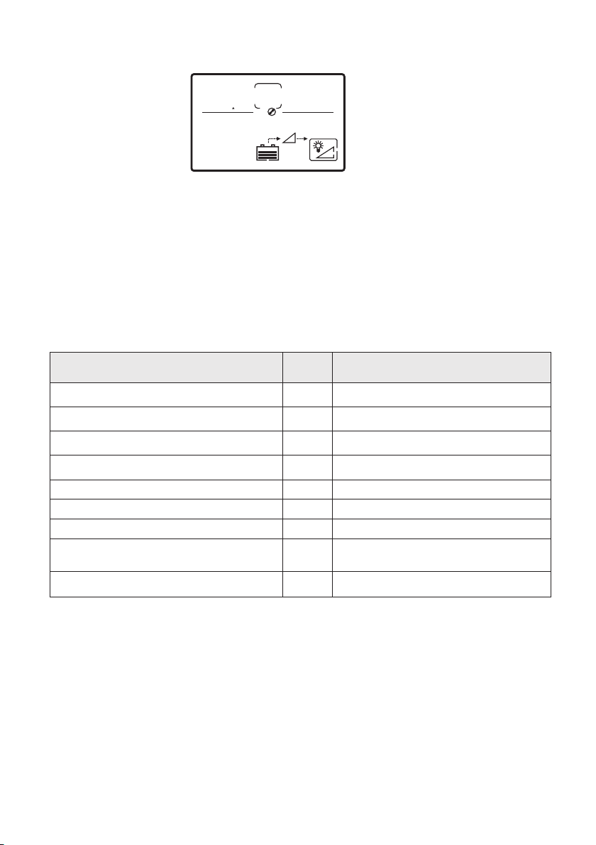
6-3 Display Overview:
231
v
BATT
1
234
v
OUTPUT
~
100%
Display Notes:
Press ‘’ESC’’ to select the indication of the Icon 3 (Output voltage, current, power, frequency)
Press “Up” to select or set auto switch the data of Icon 3.
Press and hold "UP" and "DOWN" button 3 seconds at the same time until the display backlight
flashes 3 times and the data parameters are restored to the factory default values;
When no fault , the LCD screen backlight automatically turns off when the button is not operated for
30s. When there is a fault or the buttons are pressed, the LCD screen automatically lights up.
No. Icon
1
3
4
5
6
231
v
BATT
2
1
v
234
OUTPUT
~
100%
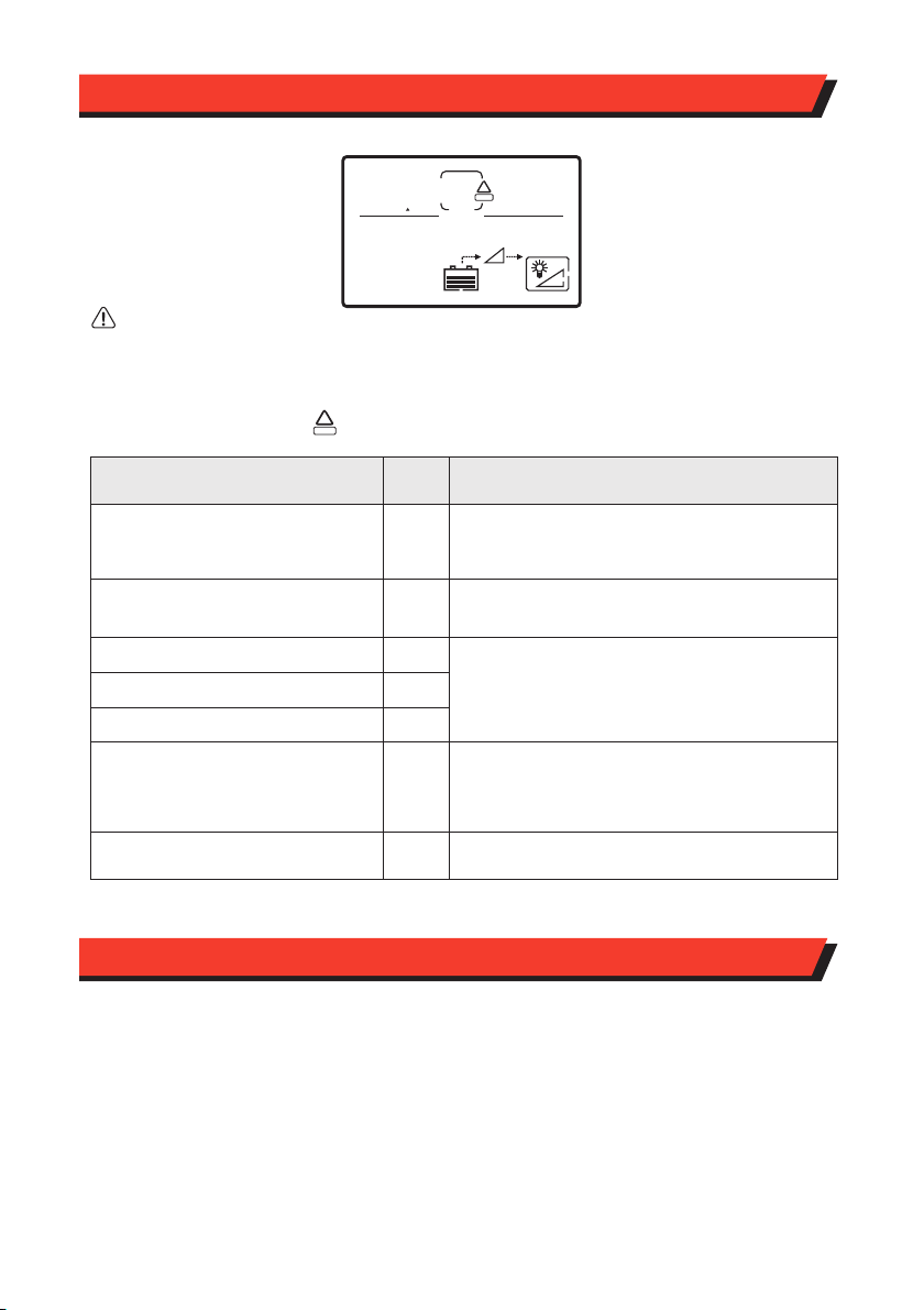
Function description
Battery output voltage
Indicates output voltage, current, power, frequency
Battery level
DC/AC inverter is in operating mode
Indicates the percentage of load level
Warning and fault codes
When the inverter is running normal, the icon will rotate
clockwise. When the inverter detects a fault, the
corresponding fault code will appear.
6. OPERATION
6-1 Operation - General
Once your inverter is installed and connected to batteries, switch the inverter on using the main
power switch. Your inverter will now be ready to use, simply plug in an appliance and operate. The
digital LCD control can be used as detailed below.
Warning: Do not intentionally use an appliance that is above the inverters maximum output
rating. This will cause the inverter to shut down and in some cases may damage the inverter.
This inverter features a digital LCD display which can be used to view status information and
control certain parameters as outlined below.
1. SET/OK: Setting button, enter button
2. UP: Setting button (UP)
3. DOWN: Setting button (DOWN)
4. MENU/ESC: Menu button, exit button
5. ON/OFF: Power on/off switch
6-2 LCD Display and Controls:

6-4 Setting Inverter Parameters:
5
0
1
v
BATT
01
~
100%
1. Press "SET/OK" for 5s. You are now entering the settings interface. As shown above.
2. Press "UP and DOWN" to adjust parameters.
3. Press "SET/OK" to confirm adjustment.
4. To reset the parameters press "set" and the ICON 1 will flash.
5. Pressing "ESC" will cancel this step and redirect you too the setting interface.
6. Press and hold "ESC" for 5s to exit the settings interface.
7. If there is no activity for 10s the inverter display will go back to the main menu.
Setting interface
Undervoltage protection value
Undervoltage recovery value
Overvoltage protection value
Overvoltage recovery value
Overload short circuit mode
Overload setting value
Overload short circuit restart delay value
Code Range
01
02
03
04
05
06
07
Default:0 Setting 0: lock 1:restart
Default:110% Setting:105-120%
Default:10 Setting: 5-60S
Default:0
Setting 0:Open 1:Close
08
Alarming mode
Notes:
Undervoltage warning value = undervoltage closing value + 0.5V, overvoltage warning value = overvoltage
closing value - 0.5V.
12V Default:14.7 Setting:14.5-15.0
12V Default:10.5 Setting:10.0-11.0
12V Default:12.0 Setting:11.5-12.5
12V Default:15.3 Setting:15.2-16.0
Manufacturer use only
09
Diagnostic setting

8. MAINTENANCE
Fault Code Solution
Battery low voltage
Battery over voltage
Front-end circuit over temperature
Back-end circuit over temperature
Front and backend over temperature
Output overload
Output short circuit
01
02
03
04
05
08
09
Stop using the inverter and charge the battery
Check cable length & gauge size for excessive
voltage drop
Check the battery voltage is below 15V;
Check the charging voltage
Disconnect the loads and check if it is short circuit
7. TROUBLE SHOOTING
Warning
Do not open or disassemble the inverter. Attempting to service the unit yourself may result in a risk of
electrical shock or fire.
Reduce loads being used so that it is below the
rated power of the unit. Please note that inductive
or capacitive loads may be several times higher
than their rated power upon start up.
Ensure the inverter has adequate ventilation and
is being used at a suitable temperature (0-40°)
Please note: extended periods of use can
cause overheating
You should clean the exterior of the unit periodically to prevent accumulation of dust and dirt.
At the same time, tighten the screws on the DC input terminals.
When faults occur: The icon indicates the corresponding fault code and flashes for attention
!
ERROR
6
5
1
v
BATT
02
000
v
OUTPUT
~
100%
!
ERROR

KICKASS PRODUCT QUALITY
QUESTIONS AND COMMENTS
This KickAss® product comes with
a 2 year warranty for your peace of
mind. In the unlikely event this
product fails when used according
to our user guide, we will either
repair or replace it.
In Australia, our goods come with guarantees that cannot be excluded under
the Australian Consumer Law. You are entitled to a replacement or refund for
a major failure and compensation for any other reasonably foreseeable loss or
damage. You are also entitled to have the goods repaired or replaced if the
goods fail to be of acceptable quality and the failure does not amount to a
major failure.
Warranty does not cover products that have not been used in accordance with
the KickAss® user guide or are outside the warranty terms and conditions.
Please visit us at supportportal.kickassproducts.com.au
This manual suits for next models
3
Table of contents
Other KICK ASS Inverter manuals
Popular Inverter manuals by other brands

SolarEdge
SolarEdge SE3680H installation guide

Champion Global Power Equipment
Champion Global Power Equipment 200953 Operator's manual

Growatt
Growatt CP100 installation manual

Nature Power
Nature Power Solar Security Light 1600 user manual

Dynamic Power
Dynamic Power TriFuel owner's manual

Rigol
Rigol DG4000 Series Service manual