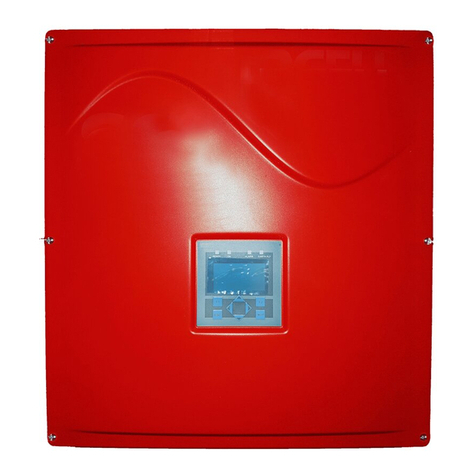
Sun Power SPR-5000m User manual

SPR50-80m-IUS102630 | TB-SPR50_60_70M | DMS#. 001-16803 Rev *E
US
PV-Inverter
SunPower
SPR-5000m / SPR-6000m / SPR-7000m / SPR-8000m
Installation Guide
SPR50-80m-IUS102630 | TB-SPR50_60_70M | DMS# 001-65188 Rev. **


SunPower
Installation Guide SPR50-80m-IUS102630 3
Copyright © 2010 SunPower, Corp. All rights reserved.
SunPower Corporation
3939N. First Street
San Jose, California 95134, USA
Tel 1-887-SUN-0123
Fax 408.877.1808

SunPower
4 SPR50-80m-IUS102630 Installation Guide
IMPORTANT SAFETY INSTRUCTIONS
SAVE THESE INSTRUCTIONS
This manual contains important instructions that shall be followed during installation and maintenance
of the follwing types of SunPower inverters:
• SPR‑5000m
• SPR‑6000m
• SPR‑7000m
• SPR‑8000m
The inverter is designed and tested according to international safety requirements, but as with all
electrical and electronic equipment, certain precautions must be observed when installing and/or
operating the inverter. To reduce the risk of personal injury and to ensure the safe installation and
operation of the inverter, you must carefully read and follow all instructions, cautions and warnings in
this Installation Guide.
Warnings
A Warning describes a hazard to equipment or personnel. It calls attention to a procedure or
practice, which, if not correctly performed or adhered to, could result in damage to or destruction of
part or all of the SunPower equipment and/or other equipment connected to the SunPower equipment
or personal injury.
DANGER
DANGER indicates a hazardous situation which, if not avoided, will result in death or
serious injury.
WARNING
WARNING indicates a hazardous situation which, if not avoided, could result in death or
serious injury.
CAUTION
CAUTION indicates a hazardous situation which, if not avoided, could result in minor or
moderate injury.
NOTICE
NOTICE is used to address practices not related to personal injury.

SunPower
Installation Guide SPR50-80m-IUS102630 5
Other symbols
In addition to the safety and hazard symbols described on the previous pages, the following symbol
is also used in this Installation Guide:
Markings on this product
The following symbols are used as markings on this product with the following meanings.
This symbol accompanies notes that call attention to supplementary information that you
should know and use to ensure optimal operation of the system.
Warning regarding dangerous voltage
The product works with high voltages. All work on the product may only be done as
described in its documentation.
Beware of hot surface
The product can become hot during operation. Do not touch the product during
operation.
Observe the operating instructions
Read the product’s documentation before working on it. Follow all safety precautions
and instructions as described in the documentation.
AC current
DC current
Earth Ground
This inverter is evaluated to UL 1741, which includes assessment to all of the
requirements of IEEE1547 and IEEE1547.1, which are an outgrowth and further
development of the IEEE recommended practices and guidelines contained in IEEE
Std.929-2000. IEEE 929-2000 provides recommendations regarding the proper
equipment and functionality necessary to ensure compatible operation when power
generation is connected to the utility grid.

SunPower
6 SPR50-80m-IUS102630 Installation Guide
General warnings
General Warnings
All electrical installations must be done in accordance with the local and National Electrical
Code ANSI/NFPA 70.
The inverter contains no user-serviceable parts except for the fans on the bottom of the
enclosure and the handle covers on the sides of the unit. For all repair and maintenance
always return the unit to an authorized SunPower Service Center.
Before installing or using the inverter, read all of the instructions, cautions, and warnings
on the inverter, the PV array, in this Installation Guide.
Before connecting the inverter to the electrical utility grid, contact the local utility company.
This connection must be made only by qualified personnel.
PV arrays produce electrical energy when exposed to light and thus can create an
electrical shock hazard. Wiring of the PV-arrays should only be performed by qualified
personnel.

SunPower
Installation Guide SPR50-80m-IUS102630 7
Warranty
All SunPower inverters sold in the USA have a ten-year warranty, as indicated on the warranty card
included in the SunPower shipping container. For warranty coverage, or if you have questions about
the SunPower warranty, contact SunPower at the address, telephone number or Web site listed on
page 3 (to send E-mail, see the Contact section of the SunPower Web site).
SUNPOWER LIMITED WARRANTY FOR PV INVERTERS
SPR-5000m, SPR-6000m, SPR-7000m, SPR-8000m
1. Limited Product Warranty and exclusions
SunPower Corporation with offices at 3939 North First Street, San Jose CA 95134 (“SunPower”)
provides a limited warranty that covers defects of your SPR-3000m, SPR-4000m, SPR-5000m, SPR-
6000m, SPR-7000m or SPR-8000m inverter (each, the “Inverter”) caused by material or
manufacturing faults. The warranty period is for 10 years and begins on the date of purchase by the
original end user.
Warranty claims may only be made by, or on the behalf of, the original end customer or a person to
whom title has been transferred for the home or premises on which the solar inverter were originally
installed.
SunPower will, at its option, repair or replace the defective component(s) free of charge, provided
that SunPower is notified of the defect during the warranty period and a dated proof of purchase is
furnished. SunPower reserves the right to inspect the faulty component(s) and determine if the defect
is due to material or manufacturing flaws. SunPower also reserves the right to charge for service time
expended if the defect is not due to material or manufacturing flaws or is not for some other reason
subject to this limited warranty.
SunPower does not warrant inverters from any and all defects or damage caused by:
a) Normal wear and tear
b) Shipping or transportation damages
c) Improper installation
d) Exposure to unsuitable environmental conditions (including but not limited to damage due to
lightning strikes)
e) Unauthorized or abnormal use or operation
f) Negligence or accidents
g) Material or workmanship not provided by SunPower or its authorized service centers
h) This warranty does not cover costs related to the removal, installation, or troubleshooting of your
electrical systems

SunPower
8 SPR50-80m-IUS102630 Installation Guide
SunPower will, at its option, use new and/or reconditioned parts in performing warranty repair and
in building replacement products. SunPower reserves the right to use parts or products of original or
improved design in the repair or replacement. If SunPower repairs or replaces a product, its warranty
continues for the remaining portion of the original warranty period or 90 days from the date of the
return shipment to the customer, whichever period expires later. All replaced products and all parts
removed from repaired products become the property of SunPower. SunPower covers both parts and
labor necessary to repair the product and return shipment to the customer, via a SunPower selected
non-expedited surface freight carrier within the United States and Canada. The warranty does not
cover any cost associated with installation, removal or re-installation of the Inverter.
2. Limitation of Warranty Scope
EXCEPT FOR THIS EXPRESS LIMITED WARRANTY, SUNPOWER EXPRESSLY EXCLUDES ALL
WARRANTIES WITH RESPECT TO THE INVERTER, EXPRESS AND IMPLIED, INCLUDING BUT NOT
LIMITED TO THE WARRANTY OF MERCHANTABILITY, THE WARRANTY OF FITNESS FOR
PARTICULAR PURPOSE, AND ANY WARRANTIES THAT MAY HAVE ARISEN FROM COURSE OF
DEALING OR USAGE OF TRADE.
TO THE MAXIMUM EXTENT PERMITTED BY LAW, SUNPOWER’S AGGREGATE MONETARY
LIABILITY TO THE CUSTOMER FOR ANY REASON AND FOR ANY AND ALL CAUSES OF ACTION,
WHETHER IN CONTRACT, TORT OR OTHERWISE, WILL NOT EXCEED THE AMOUNT PAID TO
SUNPOWER FOR THE INVERTER. SUNPOWER WILL NOT BE LIABLE TO YOU UNDER ANY
CAUSE OF ACTION, WHETHER IN CONTRACT, TORT OR OTHERWISE, FOR ANY INDIRECT,
SPECIAL, INCIDENTAL, CONSEQUENTIAL, OR PUNITIVE DAMAGES. THE PRICE FOR THE
INVERTER AND SUNPOWER’S OBLIGATIONS UNDER THIS EXPRESS LIMITED WARRANTY ARE
CONSIDERATION FOR LIMITING SUNPOWER’S LIABILITY.
IF THIS PRODUCT IS A CONSUMER PRODUCT, FEDERAL LAW DOES NOT ALLOW AN
EXCLUSION OF IMPLIED WARRANTIES. TO THE EXTENT YOU ARE ENTITLED TO IMPLIED
WARRANTIES UNDER FEDERAL LAW, TO THE EXTENT PERMITTED BY APPLICABLE LAW THEY ARE
LIMITED TO THE DURATION OF THIS LIMITED WARRANTY. SOME STATES AND PROVINCES DO
NOT ALLOW LIMITATIONS OR EXCLUSIONS ON IMPLIED WARRANTIES OR ON THE
DURATION OF AN IMPLIED WARRANTY OR ON THE LIMITATION OR EXCLUSION OF
INCIDENTAL OR CONSEQUENTIAL DAMAGES, SO THE ABOVE LIMITATION(S) OR
EXCLUSION(S) MAY NOT APPLY TO YOU. THIS LIMITED WARRANTY GIVES YOU SPECIFIC
LEGAL RIGHTS. YOU MAY HAVE OTHER RIGHTS WHICH MAY VARY FROM STATE TO STATE OR
PROVINCE TO PROVINCE.
3. Obtaining Warranty Performance
If you feel you have a justified claim covered by this Limited Warranty, please notify the solar installer,
from whom you purchased the Inverter.

SunPower Table of Contents
Installation Guide SPR50-80m-IUS102630 9
Table of Contents
1 Introduction. . . . . . . . . . . . . . . . . . . . . . . . . . . . . . . . . . . . . 13
1.1 Target group . . . . . . . . . . . . . . . . . . . . . . . . . . . . . . . . . . . . . . . 13
1.2 Product overview . . . . . . . . . . . . . . . . . . . . . . . . . . . . . . . . . . . 14
1.3 Safety . . . . . . . . . . . . . . . . . . . . . . . . . . . . . . . . . . . . . . . . . . . . 15
1.4 Installation overview . . . . . . . . . . . . . . . . . . . . . . . . . . . . . . . . . 17
2 Unpacking and inspection. . . . . . . . . . . . . . . . . . . . . . . . . 18
2.1 Scope of delivery . . . . . . . . . . . . . . . . . . . . . . . . . . . . . . . . . . . 19
3 AC voltage configuration . . . . . . . . . . . . . . . . . . . . . . . . . 20
3.1 Opening the inverter. . . . . . . . . . . . . . . . . . . . . . . . . . . . . . . . . 20
3.2 Locating internal components . . . . . . . . . . . . . . . . . . . . . . . . . . 21
3.2.1 Configuring the AC voltage . . . . . . . . . . . . . . . . . . . . . . . . . . . . . . . . . . . . . 23
3.3 Utility configuration jumpers . . . . . . . . . . . . . . . . . . . . . . . . . . . 26
4 Mounting. . . . . . . . . . . . . . . . . . . . . . . . . . . . . . . . . . . . . . . 28
4.1 Choosing a mounting location . . . . . . . . . . . . . . . . . . . . . . . . . 28
4.1.1 Selection of the mounting location . . . . . . . . . . . . . . . . . . . . . . . . . . . . . . . . 28
4.1.2 Ambient conditions . . . . . . . . . . . . . . . . . . . . . . . . . . . . . . . . . . . . . . . . . . . . 29
4.1.3 Position . . . . . . . . . . . . . . . . . . . . . . . . . . . . . . . . . . . . . . . . . . . . . . . . . . . . . 29
4.2 Dimensions and required clearances . . . . . . . . . . . . . . . . . . . . 30
4.3 Mounting procedure. . . . . . . . . . . . . . . . . . . . . . . . . . . . . . . . . 33
4.3.1 Mounting the wall-mounting bracket. . . . . . . . . . . . . . . . . . . . . . . . . . . . . . . 33
4.3.2 Mounting the DC-disconnect (if applicable) . . . . . . . . . . . . . . . . . . . . . . . . . 35
4.3.3 Mounting the inverter . . . . . . . . . . . . . . . . . . . . . . . . . . . . . . . . . . . . . . . . . . 36
5 Wiring the inverter. . . . . . . . . . . . . . . . . . . . . . . . . . . . . . . 38
5.1 Sequence of connecting . . . . . . . . . . . . . . . . . . . . . . . . . . . . . . 40
5.1.1 Wiring without DC-disconnect. . . . . . . . . . . . . . . . . . . . . . . . . . . . . . . . . . . . 40
5.1.2 Wiring with DC-disconnect . . . . . . . . . . . . . . . . . . . . . . . . . . . . . . . . . . . . . . 41
5.2 Bottom view and dimensions . . . . . . . . . . . . . . . . . . . . . . . . . . 42

SunPower Table of Contents
Installation Guide SPR50-80m-IUS102630 10
5.3 Opening the inverter. . . . . . . . . . . . . . . . . . . . . . . . . . . . . . . . . 42
5.4 Opening the DC-disconnect (if applicable) . . . . . . . . . . . . . . . 43
5.5 Wiring the AC output . . . . . . . . . . . . . . . . . . . . . . . . . . . . . . . . 44
5.5.1 AC connection requirements. . . . . . . . . . . . . . . . . . . . . . . . . . . . . . . . . . . . . 44
5.5.2 AC wiring without DC-disconnect . . . . . . . . . . . . . . . . . . . . . . . . . . . . . . . . . 49
5.5.3 AC wiring with DC-disconnect. . . . . . . . . . . . . . . . . . . . . . . . . . . . . . . . . . . . 52
5.6 Wiring the DC input . . . . . . . . . . . . . . . . . . . . . . . . . . . . . . . . . 55
5.6.1 DC connection requirements. . . . . . . . . . . . . . . . . . . . . . . . . . . . . . . . . . . . . 56
5.7 DC input grounding . . . . . . . . . . . . . . . . . . . . . . . . . . . . . . . . . 57
5.8 Connecting the DC wires . . . . . . . . . . . . . . . . . . . . . . . . . . . . . 58
5.8.1 DC wiring without DC-disconnect . . . . . . . . . . . . . . . . . . . . . . . . . . . . . . . . . 59
5.8.2 DC wiring with DC-disconnect. . . . . . . . . . . . . . . . . . . . . . . . . . . . . . . . . . . . 61
5.8.3 DC connection with additional DC distribution . . . . . . . . . . . . . . . . . . . . . . . 66
5.9 Communication wiring . . . . . . . . . . . . . . . . . . . . . . . . . . . . . . . 67
5.9.1 RS232 communication . . . . . . . . . . . . . . . . . . . . . . . . . . . . . . . . . . . . . . . . . 67
5.9.2 RS485 communication . . . . . . . . . . . . . . . . . . . . . . . . . . . . . . . . . . . . . . . . . 69
5.10 Closing the inverter . . . . . . . . . . . . . . . . . . . . . . . . . . . . . . . . . . 71
5.11 Closing the DC-disconnect (if applicable). . . . . . . . . . . . . . . . . 72
6 Commissioning . . . . . . . . . . . . . . . . . . . . . . . . . . . . . . . . . . 74
7 Displays and messages . . . . . . . . . . . . . . . . . . . . . . . . . . . 76
7.1 LED operation indicators. . . . . . . . . . . . . . . . . . . . . . . . . . . . . . 77
7.1.1 All LEDs are off . . . . . . . . . . . . . . . . . . . . . . . . . . . . . . . . . . . . . . . . . . . . . . . 77
7.1.2 All LEDs are on . . . . . . . . . . . . . . . . . . . . . . . . . . . . . . . . . . . . . . . . . . . . . . . 77
7.1.3 Green LED blinks three times per second . . . . . . . . . . . . . . . . . . . . . . . . . . . 78
7.1.4 Green LED blinks once per second . . . . . . . . . . . . . . . . . . . . . . . . . . . . . . . . 78
7.1.5 Green LED is on . . . . . . . . . . . . . . . . . . . . . . . . . . . . . . . . . . . . . . . . . . . . . . 78
7.1.6 Green LED is shortly off once per second . . . . . . . . . . . . . . . . . . . . . . . . . . . 79
7.2 LED fault indicators . . . . . . . . . . . . . . . . . . . . . . . . . . . . . . . . . . 79
7.2.1 Red and yellow LEDs are on . . . . . . . . . . . . . . . . . . . . . . . . . . . . . . . . . . . . . 79
7.2.2 Red LED is on . . . . . . . . . . . . . . . . . . . . . . . . . . . . . . . . . . . . . . . . . . . . . . . . 79

SunPower
Installation Guide SPR50-80m-IUS102630 11
7.2.3 Yellow LED is on . . . . . . . . . . . . . . . . . . . . . . . . . . . . . . . . . . . . . . . . . . . . . . 80
7.2.4 Yellow LED is blinking 2 times. . . . . . . . . . . . . . . . . . . . . . . . . . . . . . . . . . . . 80
7.2.5 Yellow LED is blinking 4 times. . . . . . . . . . . . . . . . . . . . . . . . . . . . . . . . . . . . 81
7.2.6 Yellow LED is blinking 5 times. . . . . . . . . . . . . . . . . . . . . . . . . . . . . . . . . . . . 81
7.3 Status messages on the LCD Display . . . . . . . . . . . . . . . . . . . . 82
7.3.1 LCD display language selection . . . . . . . . . . . . . . . . . . . . . . . . . . . . . . . . . . 84
7.4 Measuring channels and parameters . . . . . . . . . . . . . . . . . . . . 85
7.4.1 Measuring channels . . . . . . . . . . . . . . . . . . . . . . . . . . . . . . . . . . . . . . . . . . . 85
7.4.2 Operating mode . . . . . . . . . . . . . . . . . . . . . . . . . . . . . . . . . . . . . . . . . . . . . . 86
7.4.3 Inverter operating parameters. . . . . . . . . . . . . . . . . . . . . . . . . . . . . . . . . . . . 86
8 Troubleshooting . . . . . . . . . . . . . . . . . . . . . . . . . . . . . . . . . 90
8.1 General. . . . . . . . . . . . . . . . . . . . . . . . . . . . . . . . . . . . . . . . . . . 90
8.2 Error messages . . . . . . . . . . . . . . . . . . . . . . . . . . . . . . . . . . . . . 91
9 Maintenance. . . . . . . . . . . . . . . . . . . . . . . . . . . . . . . . . . . . 93
9.1 Cleaning the fans . . . . . . . . . . . . . . . . . . . . . . . . . . . . . . . . . . . 93
9.2 Cleaning the handle covers . . . . . . . . . . . . . . . . . . . . . . . . . . . 94
9.3 Testing the fans . . . . . . . . . . . . . . . . . . . . . . . . . . . . . . . . . . . . . 95
9.4 Exchanging the fuses . . . . . . . . . . . . . . . . . . . . . . . . . . . . . . . . 96
9.4.1 Exchanging the GFDI fuse within the inverter . . . . . . . . . . . . . . . . . . . . . . . . 96
9.4.2 Exchanging the PV string fuses within the DC-disconnect . . . . . . . . . . . . . . . 97
10 Technical specifications . . . . . . . . . . . . . . . . . . . . . . . . . . . 99
10.1 FCC compliance information . . . . . . . . . . . . . . . . . . . . . . . . . . 99
10.2 Wiring diagrams. . . . . . . . . . . . . . . . . . . . . . . . . . . . . . . . . . . 100
10.2.1 Without DC-disconnect . . . . . . . . . . . . . . . . . . . . . . . . . . . . . . . . . . . . . . . . 100
10.2.2 With DC-disconnect . . . . . . . . . . . . . . . . . . . . . . . . . . . . . . . . . . . . . . . . . . 101
10.3 Specifications . . . . . . . . . . . . . . . . . . . . . . . . . . . . . . . . . . . . . 102
10.4 SPR-5000m. . . . . . . . . . . . . . . . . . . . . . . . . . . . . . . . . . . . . . . 102
10.5 SPR-6000m. . . . . . . . . . . . . . . . . . . . . . . . . . . . . . . . . . . . . . . 104
10.6 SPR-7000m. . . . . . . . . . . . . . . . . . . . . . . . . . . . . . . . . . . . . . . 106

SunPower
12 SPR50-80m-IUS102630 Installation Guide
10.7 SPR-8000m. . . . . . . . . . . . . . . . . . . . . . . . . . . . . . . . . . . . . . . 108
10.7.1 DC-disconnect . . . . . . . . . . . . . . . . . . . . . . . . . . . . . . . . . . . . . . . . . . . . . . . 110
10.8 Trip limits/trip times. . . . . . . . . . . . . . . . . . . . . . . . . . . . . . . . . 110
10.9 Torque values and wire sizes . . . . . . . . . . . . . . . . . . . . . . . . . 111

SunPower Introduction
Installation Guide SPR50-80m-IUS102630 13
1 Introduction
This installation guide provides all the information needed to install, commission and operate
SunPower grid-tied photovoltaic (PV) inverters of the following types:
• SPR-5000m
• SPR-6000m
• SPR-7000m
• SPR-8000m
1.1 Target group
This manual is for qualified personnel. Qualified personnel has received training and has
demonstrated skills and knowledge in the construction and operation of the device. Qualified
personnel is trained to deal with the dangers and hazards involved in installing electric devices.
To help avoid problems during the installation, familiarize yourself with the installation
process by reading the entire Installation Guide before starting the installation.
WARNING
Lethal voltages are present at various points in a PV system. For safety reasons only
qualified personnel may install and operate this equipment.

Introduction SunPower
14 SPR50-80m-IUS102630 Installation Guide
1.2 Product overview
The SunPower SPR-5000m/SPR-6000m/SPR-7000m/SPR-8000m is a DC to AC grid-tied utility
interactive inverter for use with photovoltaic (PV), fuel cell, wind turbine and other sources of DC
power. For the use with a wind turbine
In general, the inverter takes power from a DC source (PV modules) and converts it to AC power for
the utility grid. This power is delivered first to local loads (household appliances, lights, motor loads,
etc.), with any excess power fed to the utility. The power consumed by the local loads reduces the
power needed from the utility. Excess power may actually “spin the utility meter backwards”
depending on the type of meter in your system. This power may also be recorded as power credits
by the utility company depending on the interconnection agreement. An example of basic system
components is shown in figure below.
Position Description
A PV array
BInverter with DC-Disconnect
C Local loads
D Meter
EUtility grid
Policies vary from one utility company to another. Consult with a representative of the local
utility company before designing and installing a PV system.

SunPower Introduction
Installation Guide SPR50-80m-IUS102630 15
1.3 Safety
Anti-islanding protection
Islanding is a condition that can occur if the utility grid is disconnected while the inverter is operating
and the remaining load is resonant at 60Hz and matches the output of the inverter perfectly. This
condition is highly unlikely and had never been witnessed outside of a controlled laboratory.
Nevertheless, the inverter incorporates an advanced active islanding protection algorithm to ensure
that the system will not export power into a balanced 60Hz resonant load while the utility is
disconnected. The inverter periodically injects both leading and lagging reactive current into the utility
grid. This method has been proven by Underwriters Laboratories to effectively destabilize and
disconnect from a balanced island condition.
PV ground fault detection and interruption
The inverter is equipped with a ground fault detection device. If a ground fault current greater than
1A is detected, the inverter will shut down and display the fault condition on the user interface
display. Once the ground fault is located and corrected, the ground fault error will need to be
manually cleared and the inverter will then resume normal operation.
PV series fusing
Series fusing may be required depending on the type of PV module used in the system. See NEC
690.9
Interconnection code compliance
The inverter has been tested and listed by Underwriters Laboratories to meet the requirements of
UL1741 Static Inverters and Charge Controllers for use in Photovoltaic Power Systems and UL1998
Software in Programmable Components, as well as IEEE-929-2000 Recommended Practice for Utility
Interface of Photovoltaic Systems and IEEE 1547 Standard for Interconnecting Distributed Resources
with Electric Power Systems. The inverter is cUL listed to CSA standard No. c22.2 107.1-01.
FCC compliance
The SunPower SPR-5000m/SPR-6000m/SPR-7000m/SPR-8000m has been tested and certified by
a nationally recognized testing laboratory and conforms to all FCC Part 15 A & B EMI/EMC
emissions regulations.
Contact the local utility and/or the authority having jurisdiction prior to connecting the
inverter to the utility grid.

Introduction SunPower
16 SPR50-80m-IUS102630 Installation Guide
Feature overview
Over twenty years of inverter manufacturing experience has gone into the design of the SunPower
SPR-5000m/SPR-6000m/SPR-7000m/SPR-8000m PV inverter. As a result, the inverter represents
state-of-the-art technology, high reliability and over all ease of use - all the qualities you’ve come to
expect from SunPower. Some of the features included are:
• High efficiency
• Auto line voltage detection and configuration
• Temperature regulated fan cooling with simplified fan replacement
• Advanced communication options
•LCD Display
• Powder coated die-cast enclosure
• Compatible with all SunPower inverter products
•Quiet operation
• Simple installation
Operating temperature
The inverter has been designed to maintain full power output at ambient temperatures as high as
+113°F (+45°C). Fan cooling allows this level of output power to be achieved even in enclosed
spaces. The inverter will continue to operate well beyond +113°F (+45°C) and de-rates as needed
to maintain a safe internal component temperature.

SunPower Introduction
Installation Guide SPR50-80m-IUS102630 17
1.4 Installation overview
This section provides a high-level overview of the installation process so you have an idea what to
expect as you proceed through the rest of the installation guide.
The installation process is broken down into the following tasks:
Section 2: Unpacking and inspection
This section provides instructions and information for unpacking the inverter and inspecting it for
shipping damage.
Section 3: AC voltage configuration
This section includes information on removing the lid, locating primary components within the inverter
and selecting the appropriate voltage configuration for the installation.
Section 4: Mounting
This section includes guidelines to help you select the best mounting location, suggestions to insure
optimum performance, cautions and warnings that you should follow to avoid injury and/or
equipment damage and step-by-step instructions for mounting the inverter.
Section 5: Wiring the inverter
This section includes guidelines for selecting the correct wire sizes, cautions and warnings that you
should follow to avoid injury and/or equipment damage and step-by-step instructions for wiring the
inverter to a PV array, household electrical circuits and the utility grid. Procedures are also included
for connecting optional data-communication cables.
Section 6: Commissioning
Commissioning involves applying DC input power to the inverter, observing the LED and LCD
indicators on the front lid, and resolving any problems that occur.
Section 7: Displays and messages
This section provides troubleshooting tips and procedures for resolving problems that may occur
during installation and operation.
Section 8: Troubleshooting
This section provides troubleshooting tips and procedures for resolving problems that may occur
during installation and operation.
Section 9: Maintenance
This section includes maintenance and cleaning of the inverter and cautions and warnings you should
follow to avoid injury and/or equipment damage.
Section 10: Technical specifications
This section includes technical data for the inverter, connection diagrams and torque specifications for
the connection of cables and the screws of the inverter.

Unpacking and inspection SunPower
18 SPR50-80m-IUS102630 Installation Guide
2 Unpacking and inspection
All inverters are thoroughly tested and inspected before they are packed and shipped. Although they
are shipped in sturdy, recyclable packaging; damage can still occur during shipping. It is important
to carefully inspect the shipping container prior to beginning the installation. If any external damage
to the packaging makes you suspect the inverter itself could be damaged, or if you find that the
inverter is damaged after unpacking it, report the damage immediately to your SunPower dealer and
to the shipping company that delivered the inverter. If it becomes necessary to return the inverter, use
the original packaging in which it was delivered.
If you need assistance with a damaged inverter, contact your SunPower dealer or SunPower. Contact
information for SunPower is provided below.
SunPower Corp.
3939N. First Street
San Jose, California 95134, USA
Tel 1-877-SUN-0123
Fax 408.877.1808
WARNING
The inverter weighs 148lbs. (67kg). To avoid injury, be sure to use proper lifting
techniques and secure the help of someone to assist in the unpacking and installation of
the inverter.

SunPower Unpacking and inspection
Installation Guide SPR50-80m-IUS102630 19
2.1 Scope of delivery
SunPower SPR-5000m/SPR-6000m/SPR-7000m/SPR-8000m PV inverter:
DC-Disconnect (if applicable):
Position Number Description
A1Inverter
B 1 Wall-mounting bracket
C 3 1 Spare screw and washer for closing the inverter lid.
2 screws and washers for fastening the inverter to the wall-
mounting bracket.
D 2 Spare jumpers for the fan test and for the grid configuration.
E 2 Handle covers for left and right side.
Position Number Description
F1DC-Disconnect
G 3 1 screw and one washer for closing the DC-Disconnect lid.
2 screws and washers for fastening the DC-Disconnect to the wall-
mounting bracket.

AC voltage configuration SunPower
20 SPR50-80m-IUS102630 Installation Guide
3 AC voltage configuration
3.1 Opening the inverter
1. Remove the 6 screws and lock washers from the enclosure lid and pull the lid forward smoothly.
2. Place the lid, screws, and lock washers aside where they will be out of your way while you are
connecting wires and cables to the inverter.
CAUTION
Be careful not to misplace the screws or the lock washers, as all six screws and lock
washers are required to ensure that the lid is grounded properly and is fully sealed to the
case. Handle the lid carefully, as even minor damage to the lid could result in an
inadequate seal between the lid and the case, thus allowing moisture to enter the case and
damage the sensitive electronic components.
NOTICE
Do not install the inverter during periods of precipitation or high humidity (>95%).
Moisture trapped within the enclosure may cause corrosion and damage to the electronic
components.
This manual suits for next models
3
Other Sun Power Inverter manuals