Electrolux Professional EUCA060 User manual
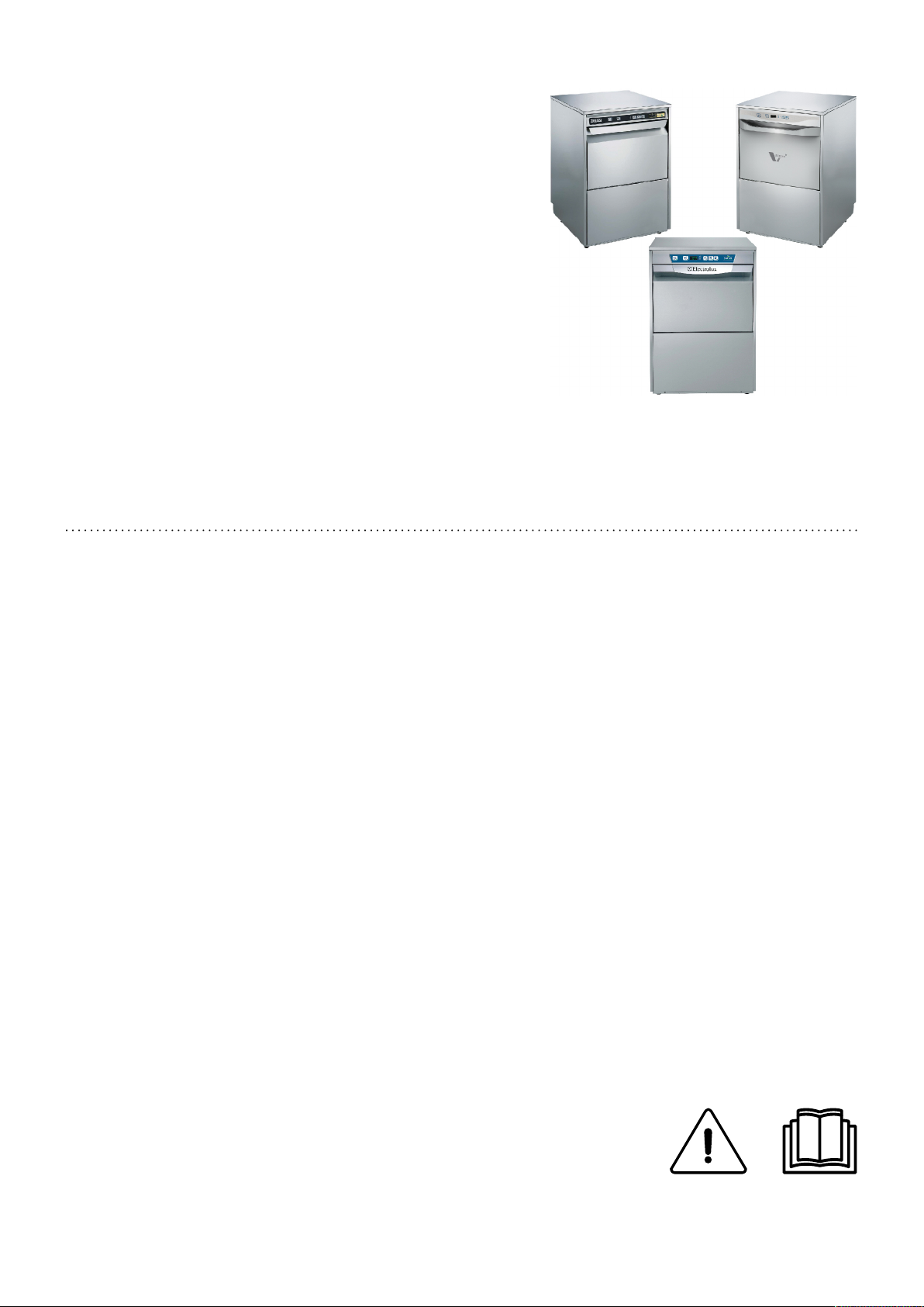
Under Counter Dishwasher
EUCA060 - ZUCA060 - VUCA060
EN Installation and operating manual *
*Original instructions 59566V500- 2020.06

2
Installation diagram
600
508
431
403
379
155
612
30
850
XD
WIEI
D
D
XD WIEIEQ
820
431
987
6958
EQ
WI
EI
Ø = 20
(750.........1000)

3
EI = Power supply entry
WI = Water Inlet pipe with ⌀=3/4″ G fittings
XD = Inlet pipe for detergents
EQ = Equipotential screw
D = Drain pipe with internal diameter:
⌀= 20 mm (Only for model with drain pump)

4
Foreword
The installation, use and maintenance manual (hereinafter Manual) provides the user with information necessary for correct
and safe use of the machine (or “appliance“).
The following must not be considered a long and exacting list of warnings, but rather a set of instructions suitable for improving
machine performance in every respect and, above all, preventing injury to persons and animals and damage to property due to im-
proper operating procedures.
All persons involved in machine transport, installation, commissioning, use and maintenance, repair and disassembly must con-
sult and carefully read this manual before carrying out the various operations, in order to avoid wrong and improper actions that
could compromise the machine's integrity or endanger people. Make sure to periodically inform the user regarding the safety regu-
lations. It is also important to instruct and update personnel authorised to operate on the machine, regarding its use and
maintenance.
The manual must be available to operators and carefully kept in the place where the machine is used, so that it is always at hand
for consultation in case of doubts or whenever required.
If, after reading this manual, there are still doubts regarding machine use, do not hesitate to contact the Manufacturer or the au-
thorised Service Centre to receive prompt and precise assistance for better operation and maximum efficiency of the machine.
During all stages of machine use, always respect the current regulations on safety, work hygiene and environmental protection. It
is the user's responsibility to make sure the machine is started and operated only in optimum conditions of safety for people, ani-
mals and property.
IMPORTANT
• The manufacturer declines any liability for operations carried out on the appliance without respecting the instructions
given in this manual.
• The manufacturer reserves the right to modify the appliances presented in this publication without notice.
• No part of this manual may be reproduced.
• This manual is available in digital format by:
– contacting the dealer or reference customer care;
– downloading the latest and up to date manual on the web site;
• The manual must always be kept in an easily accessed place near the machine. Machine operators and mainte-
nance personnel must be able to easily find and consult it at any time.

5
Contents
A SAFETY INSTRUCTIONS .......................................................................................................................7
A.1 General safety .............................................................................................................................7
B GENERAL INFORMATION ......................................................................................................................7
B.1 Introduction .................................................................................................................................7
B.2 General safety instructions .............................................................................................................7
B.3 Additional indications.....................................................................................................................7
B.4 Definitions...................................................................................................................................7
B.5 Machine and Manufacturer’s identification data ...................................................................................8
B.6 How to identify the technical data ..................................................................................................... 8
B.6.1 How to interpret the factory description ....................................................................................8
B.7 Type reference.............................................................................................................................8
B.8 Copyright....................................................................................................................................9
B.9 Responsibility ..............................................................................................................................9
B.10 Keeping the manual ......................................................................................................................9
B.11 Recipients of the manual ................................................................................................................ 9
B.12 Personal protection equipment ........................................................................................................9
C TECHNICAL DATA............................................................................................................................... 10
C.1 Main technical characteristics........................................................................................................ 10
C.2 Characteristics of power supply ..................................................................................................... 10
D TRANSPORT, HANDLING AND STORAGE .............................................................................................. 11
D.1 Introduction ............................................................................................................................... 11
D.2 Transport: instructions for the carrier............................................................................................... 11
D.3 Procedures for handling operations ................................................................................................ 11
D.4 Shifting..................................................................................................................................... 11
D.5 Placing the load ......................................................................................................................... 11
D.6 Storage .................................................................................................................................... 12
E INSTALLATION AND ASSEMBLY ........................................................................................................... 12
E.1 Introduction ............................................................................................................................... 12
E.2 Customer responsibilities ............................................................................................................. 12
E.3 Characteristics of the installation place............................................................................................ 12
E.4 Positioning................................................................................................................................ 12
E.5 Disposal of packing..................................................................................................................... 13
E.6 Plumbing connections ................................................................................................................. 13
E.7 Plumbing circuits ........................................................................................................................ 14
E.8 Electrical connections.................................................................................................................. 14
E.8.1 Connections provided for energy control ................................................................................ 15
E.9 Safety devices ........................................................................................................................... 15
E.10 Detergent/rinse aid dispensers and prearrangements......................................................................... 15
F COMMISSIONING ............................................................................................................................... 16
F.1 Preliminary checks, adjustments and operational tests ....................................................................... 16
G BEFORE FIRST USE ........................................................................................................................... 16
G.1 Manual activation ....................................................................................................................... 16
G.2 Setting the dispensers ................................................................................................................. 16
G.2.1 Peristaltic dispenser .......................................................................................................... 17
H GENERAL SAFETY RULES................................................................................................................... 17
H.1 Introduction ............................................................................................................................... 17
H.2 Guards..................................................................................................................................... 17
H.3 Safety signs to be placed on the machine or near its area.................................................................... 17
H.4 Instructions for use and maintenance.............................................................................................. 18
H.5 Reasonably foreseeable improper use ............................................................................................ 18
H.6 Residual risks ............................................................................................................................ 18
I CONTROL PANEL ............................................................................................................................... 19
I.1 Control panel description.............................................................................................................. 19
I.2 Basic Controls ........................................................................................................................... 20
J NORMAL MACHINE USE...................................................................................................................... 20
J.1 Foreseen use ............................................................................................................................ 20
J.2 Operator qualified for normal machine use ....................................................................................... 20
J.3 Starting .................................................................................................................................... 20
J.4 Wash cycles.............................................................................................................................. 21
J.5 Operation ................................................................................................................................. 21
J.6 Type of racks and loading ............................................................................................................. 22
K CLEANING AND MAINTENANCE ........................................................................................................... 22
K.1 End of service and daily cleaning ................................................................................................... 22
K.1.1 Cleaning the exterior surfaces.............................................................................................. 23
K.2 Maintenance ............................................................................................................................. 23
K.2.1 Repair and extraordinary maintenance .................................................................................. 23
K.2.2 Parts and accessories........................................................................................................ 23
K.2.3 Prolonged period of inactivity ............................................................................................... 23
K.3 Boiler drainage (only for atmospheric versions) ................................................................................. 23
K.4 Only for models with door lock device ............................................................................................. 23

6
K.5 End of use ................................................................................................................................ 23
K.6 Introduction ............................................................................................................................... 23
K.7 Waste storage............................................................................................................................ 24
K.8 Procedure regarding appliance dismantling macro operations .............................................................. 24
L TROUBLESHOOTING.......................................................................................................................... 24
L.1 Common faults.......................................................................................................................... 24
L.2 Alarms ..................................................................................................................................... 25
7
A SAFETY INSTRUCTIONS
A.1 General safety
• The appliance must not be used by people (including children) with limited physical,
sensory or mental abilities or without experience and knowledge of it, unless instructed
in its use and supervised by those responsible for their safety.
CAUTION
Do not wash the appliance with direct or high pressure jets of water.
WARNING
If the power cable is damaged it must be replaced by the Customer Care
Service or in any case by specialised personnel, in order prevent any risk.
B GENERAL INFORMATION
B.1 Introduction
Given below is some information regarding the machine's
intended use, its testing, and a description of the symbols used
(that identify the type of warning), the definitions of terms used
in the manual and useful information for the appliance user.
B.2 General safety instructions
To ensure safe use of the machine and a
proper understanding of the manual it is
necessary to be familiar with the terms and
typographical conventions used in the
documentation. The following symbols are
used in the manual to indicate and identify
the various types of hazards:
WARNING
Danger for the health and safety
of operators.
WARNING
Danger of electrocution - dan-
gerous voltage.
Words further explaining the type of hazard
are placed next to the symbols in the text.
Warnings serve to ensure the safety of
personnel.
B.3 Additional indications
In this manual the risks arising from incorrect use will be
marked with:
CAUTION
Risk of damage to the machine or the
product.
The parts of the text preceded by the following symbol:
NOTE!
Clarifications and explanations
Provide recommendations to keep in mind during the entire
life-cycle of the product.
The drawings and diagrams given in the manual are not in
scale. They supplement the written information with an outline,
but are not intended to be a detailed representation of the
machine supplied.
The numerical values given on the machine installation
diagrams refer to measurements in mm.
B.4 Definitions
Listed below are the definitions of the main terms used in the
manual. It is advisable to read them carefully before use.
Operator machine installation, adjustment, use,
maintenance, cleaning, repair and trans-
port personnel.
Manufacturer Electrolux Professional SpA or any other
service centre authorised by Electrolux
Professional SpA.
Operator for
normal
machine use
an operator who has been informed and
trained regarding the tasks and hazards
involved in normal machine use.
Customer
Care service
or specialised
personnel
an operator instructed/trained by the
Manufacturer and who, based on his
professional and specific training, experi-
ence and knowledge of the accident-
prevention regulations, is able to appraise
the operations to be carried out on the
machine and recognise and prevent any
risks. His professionalism covers the
mechanical, electrotechnical and elec-
tronics fields.
Danger source of possible injury or harm to health.
Hazardous
situation
any situation where an operator is
exposed to one or more hazards.
Risk a combination of probabilities and risks of
injury or harm to health in a hazardous
situation.
Protection
devices
safety measures consisting of the use of
specific technical means (guards and
safety devices) for protecting operators
against risks.
Guard an element of a machine used in a specific
way to provide protection by means of a
physical barrier.
Safety device a device (other than a guard) that elimi-
nates or reduces the risk; it can be used
alone or in combination with a guard.

8
Customer the person who purchased the machine
and/or who manages and uses it (e. g.
company, entrepreneur, firm).
Electrocution an accidental discharge of electric current
on a human body.
B.5 Machine and Manufacturer’s
identification data
A reproduction of the marking or dataplate on the machine is
given below:
The dataplate gives the product identification and technical data;
listed below is the meaning of the various information given on it.
F.Mod. factory description of product
Comm.Model commercial description
PNC production number code
Ser.No. serial number
400V 3N power supply voltage
230V 3 - 230V 1N electric convertibility (depending
on the model)
50/60 power supply frequency
Max - kW max. power
Nominal - kW nominal power
IPX4 dust and water protection rating
CE CE marking
Electrolux Professio-
nal SpA Viale Treviso
15 33170 Pordenone
Italy
manufacturer
The dataplate is located on the right side panel of the
equipment.
WARNING
Do not remove, tamper with or
make the machine marking
illegible.
IMPORTANT
When scrapping the machine, the marking must be
destroyed.
NOTE!
Refer to the data given on the machine marking for
relations with the Manufacturer (e.g. when ordering
spare parts, etc.).
B.6 How to identify the technical data
To identify the technical data, read the factory description of
the product (F. Mod.) on the dataplate, identify the main
machine data and consult C.1 Main technical characteristics
paragraph.
B.6.1 How to interpret the factory description
The factory description on the dataplate has the following
meaning (some examples are given below):
(1) (2) (3)
E UC A060
Z UC A060
V UC A060
(1) Brand E = Electrolux
Z= Zanussi
V = Veetsan Star
(2) Machine
type
UC = Under counter
(3) Options A060 = Compliant with A060 level according
to EN 15883-1 Standard
B.7 Type reference
Legend
AType of appliance
• Under counter dishwasher
BRinsing type
• 0 = without rinse pump
• 1 = with rinse pump
CWater treatment
• 0 = without water softener [WS]
• 1 = with water softener [WS]
2017F.Mod.
Comm. Model: PNC Ser.Nr. E Hz Max 12.9 kW Nominal 9.9 kW
6.9 kWMin
Electrolux Professional spa - Viale Treviso, 15 - 33170 Pordenone (Italy)
IP
Type ref.
2016F.Mod.
Comm. Model: PNC Ser.Nr. E Hz Max 12.1 kW
Nominal 9.9 kWMin
Electrolux Professional spa - Viale Treviso, 15 - 33170 Pordenone (Italy)
IPX4
.
Electrol u x Pro f e ss ion a l s p a - Vi a le T r e vi s o , 15
F. Mod EUCA....
Ma i n t e c hn i c a l c h a r a c t e r i st i c s
MODEL
Su p p l y Ele c t r i c
P o w e r sup p ly v o l t ag eV 400 3 N
F re q uenc y H z5 0
EUCA.....
EX Made in EU 2020F.Mod. Comm.ModelPNC Ser.Nr. E V 50 Hz kWType ref.
Electrolux Professional spa - Viale Treviso, 15 - 33170 Pordenone (Italy)
IPX5
LS6
A B C
9
B.8 Copyright
This manual is intended solely for consultation by the operator
and can only be given to third parties with the permission of
Electrolux Professional SpA.
B.9 Responsibility
The Manufacturer declines any liability for damage and
malfunctioning caused by:
• non-compliance with the instructions contained in this
manual;
• repairs not carried out in a workmanlike fashion, and
replacements with parts different from those specified in
the spare parts catalogue (the fitting and use of non-original
spare parts and accessories can negatively affect machine
operation and invalidates the warranty);
• operations by non-specialised personnel;
• unauthorised modifications or operations;
• inadequate maintenance;
• improper machine use;
• unforeseeable extraordinary events;
• use of the machine by uninformed and untrained personnel;
• non-application of the current provisions in the country of
use, concerning safety, hygiene and health in the workplace.
The Manufacturer declines any liability for damage caused by
arbitrary modifications and conversions carried out by the user
or the Customer.
The employer, workplace manager or service technician are
responsible for identifying and choosing adequate and suitable
personal protection equipment to be worn by operators, in
compliance with regulations in force in the country of use.
Electrolux Professional SpA declines any liability for inaccur-
acies contained in the manual, if due to printing or translation
errors. Any supplements to the installation, use and main-
tenance manual the Customer receives from the Manufacturer
will form an integral part of the manual and therefore must be
kept together with it.
B.10 Keeping the manual
The manual must be carefully kept for the entire life of the
machine, until scrapping.
The manual must stay with the machine in case of transfer,
sale, hire, granting of use or leasing.
B.11 Recipients of the manual
This manual is intended for:
• the carrier and handling personnel;
• installation and commissioning personnel;
• the employer of machine users and the workplace
manager;
• operators for normal machine use;
• specialised personnel - Customer Care service (see service
manual).
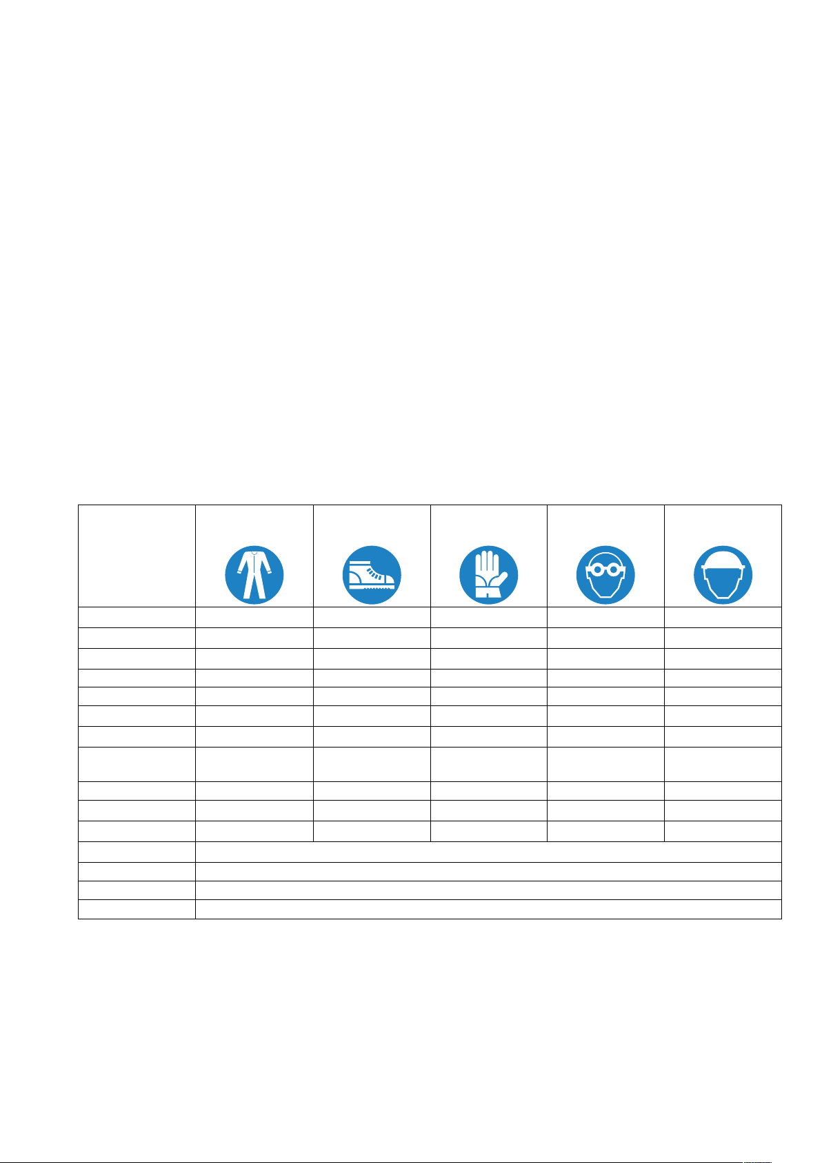
B.12 Personal protection equipment
Summary table of the Personal Protection Equipment (PPE) to be used during the various stages of the machine's
service life.
Stage Protective
garments
Safety footwear Gloves Glasses Safety helmet
Transport —● ○ —○
Handling ● ● ○ — —
Unpacking ○ ● ○ — —
Installation ○ ● ●1— —
Normal use ● ● ●2○—
Adjustments ○ ● — — —
Routine cleaning ○ ● ●1ˉ3○—
Extraordinary
cleaning
○ ● ●1ˉ3○—
Maintenance ○ ● ○ — —
Dismantling ○ ● ○ ○ —
Scrapping ○ ● ○ ○ —
Key:
●PPE REQUIRED
○PPE AVAILABLE OR TO BE USED IF NECESSARY
—PPE NOT REQUIRED
1. During these operations, gloves must be cut-resistant. Failure to use the personal protection equipment by operators, specialized personnel or users can
involve exposure to damage to health (depending on the model).
2. During these operations, gloves must be heatproof and suitable for contact with water and the substances used (refer to the safety data sheet of the
substances used for the information regarding the required PPE). Failure to use the personal protection equipment by operators, specialised personnel or
users can involve exposure to chemical risk and cause possible damage to health (depending on the model).
3. During these operations, gloves must be suitable for contact with chemical substances used (refer to the safety data sheet of the substances used for
information regarding the required PPE). Failure to use the personal protection equipment by operators, specialized personnel or users can involve exposure
to chemical risk and cause possible damage to health (depending on the model).

10
C TECHNICAL DATA
C.1 Main technical characteristics
Model EUCA060 ZUCA060 VUCA060
Supply voltage:
convertible to
single-phase version
400V 3N~
230V 3~
230V 1N~
400V 3N~
230V 3~
230V 1N~
400V 3N~
230V 3~
230V 1N~
Frequency Hz 50 50 50
Max. power kW 8.85 8.85 8.85
Boiler heating elements kW 6 6 6
Tank heating elements kW 2.0 2.0 2.0
Water supply pressure kPa
[bar]
50 - 700
[0.5 - 7]
50 - 700
[0.5 - 7]
50 - 700
[0.5 - 7]
Water supply temperature ℃[℉] 50 [122] 50 [122] 50 [122]
Water supply hardness °f/°d/°e 14/8/10 max 14/8/10 max 14/8/10 max
Electric conductivity of water μS/cm < 400 < 400 < 400
Concentration of chlorides in
water ppm < 20 < 20 < 20
Rinse cycle water consumption l
3 (for wash cycle 1 and
2)
4 (for wash cycle 3)
3 (for wash cycle 1 and
2)
4 (for wash cycle 3)
3 (for wash cycle 1)
4 (for wash cycle 2)
Boiler capacity l 12 12 12
Tank capacity l 23 23 23
Standard cycle time with water
supply at 50℃1sec.
90 (for wash cycle 1)
120 (for wash cycle 2)
240 (for wash cycle 3)
90 (for wash cycle 1)
120 (for wash cycle 2)
240 (for wash cycle 3)
90 (for wash cycle 1)
240 (for wash cycle 2)
Legal noise level Leq2dB(A) LpA: 63dB - KpA:
1.5dB
LpA: 63dB - KpA:
1.5dB
LpA: 63dB - KpA:
1.5dB
Protection rating IPX4 IPX4 IPX4
Net weigh kg 68 68 68
Power supply cable H07RN-F H07RN-F H07RN-F
1. Standard cycle time may vary should the inlet water temperature and/or the boiler heating elements be different from that indicated above.
2. The noise emission values have been obtained according to EN ISO 11204.
400 – 415V 3N 220 – 240V 3 220 – 240V 1N
C S C S C S
6.85 kW 5x2,5 mm216A 3P + N 4x2.5 mm220A 3P 3x6 mm240A 1P + N
8.85 kW 5x2,5 mm216A 3P + N 4x2.5 mm232A 3P 3x10 mm250A 1P + N
C = Power supply cable
S = On/Off switch
C.2 Characteristics of power supply
The AC power supply to the machine must meet the following conditions:
• max. voltage variation ± 6%
• max. frequency variation ± 1% continuous ± 2% for a short period.
Harmonic distorsion, unbalanced three-phase supply voltage, voltage pulses, interruption, dips and the other electric character-
istics must respect the provisions of point 4.3.2 of Standard EN 60204-1 (IEC 60204-1).
WARNING
The machine's power supply must be protected against overcurrents (short
circuits and overloads) by fuses or suitable thermal magnetic circuit breakers.
A suitable high-sensitivity manual-reset differential omnipolar thermal-
magnetic switch with contact gap enabling complete disconnection in
category III overvoltage conditions and complying with the current regula-
tions, must be installed between the power cable and the electric line.
11
WARNING
For protection against indirect contacts (depending on the type of supply
provided for and connection of earths to the equipotential protection circuit)
refer to point 6.3.3 of EN 60204-1 (IEC 60204-1) with the use of protection
devices that ensure automatic cut-off of the supply in case of isolation fault in
the TN or TT systems or, for IT systems, the use of isolation controllers or
differential current protection devices to activate automatic power disconnec-
tion (an isolation controller must be provided for indicating a possible first
earth fault of a live part, unless a protection device is supplied for switching off
the power in case of a such a fault. This device must activate an acoustic and/
or visual signal which must continue for the entire duration of the fault). For
example: in a TT system, a differential switch with cut-in current (e.g. 30 mA)
coordinated with the earthing system of the building where the machine is
located must be installed ahead of the supply.
D TRANSPORT, HANDLING AND STORAGE
D.1 Introduction
Transport (i. e. transfer of the machine from one place to
another) and handling (i. e. transfer inside workplaces) must
occur with the use of special and adequate means.
WARNING
Due to their size, the machines
cannot be stacked on top of each
other during transport, handling
and storage; this eliminates any
risks of loads tipping over due to
stacking.
NOTE!
Specialised personnel must:
• have specific technical training and experience
in the use of lifting systems;
• have knowledge of the safety regulations and
applicable laws in the relevant sector;
• have knowledge of the general safety rules;
• ensure the use of personal protection equip-
ment suitable for the type of operation carried
out;
• be able to recognise and avoid any possible
hazard.
D.2 Transport: instructions for the carrier
WARNING
Do not stand under suspended
loads during loading/ unloading
operations. Unauthorised per-
sonnel must not enter the work
area.
The weight of the appliance
alone is not sufficient to keep it
steady.
NOTE!
The transported load can shift:
• when braking;
• when accelerating;
• in corners;
• on rough roads.
D.3 Procedures for handling operations
For correct and safe lifting operations:
• use the type of equipment most suitable for characteristics
and capacity (e.g. electric pallet truck or lift truck);
• cover sharp edges;
Before lifting:
• send all operators to a safe position and prevent persons
from entering the handling area;
• make sure the load is stable;
• make sure no material can fall during lifting. Manoeuvre
vertically in order to avoid impacts;
• handle the machine, keeping it at minimum height from the
ground.
WARNING
For machine lifting and anchor-
ing, do not use movable or weak
parts such as: casings, electrical
raceways, pneumatic parts, etc.
D.4 Shifting
The operator must:
• have a general view of the path to be followed;
• stop the manoeuvre in case of hazardous situations.
WARNING
Do not push or pull the appliance
to move it, as it may tip over.
D.5 Placing the load
Before placing the load, make sure the way is free and that the
floor is flat and can take the load. Remove the appliance from
the wooden pallet, move it to one side, then slide it onto the
floor.

12
D.6 Storage
The machine and/or its parts must be stored and protected
from damp, in a non-aggressive place, free of vibrations and
with room temperatures between -10℃and 50℃. The place
where the machine is stored must have a flat support surface
to avoid deforming the machine or damage to the support feet.
WARNING
Appliance positioning, installa-
tion and disassembly must be
carried out by specialised
personnel.
CAUTION
Do not make modifications to the parts
supplied with the appliance. Any missing
or faulty parts must be replaced with
original parts.
E INSTALLATION AND ASSEMBLY
E.1 Introduction
To ensure correct operation of the appliance and maintain safe
conditions during use, carefully follow the instructions given
below in this section.
WARNING
The above operations must be
carried out by the specialised
personnel in conformity with the
current safety regulations,
regarding the equipment used
and the operating procedures.
Before moving the appliance
make sure the capacity of the
lifting equipment used is suitable
for its weight.
E.2 Customer responsibilities
The Customer must provide for the following:
• installation of an adequate electrical power supply ahead of
the appliance, according to the equipment’s technical
specifications (C.1 Main technical characteristics and C.2
Characteristics of power supply);
• the equipotential connection of the workplace electrical
system to the metal structure of the machine by means of a
copper cable of adequate section (see position “EQ“ in
Installation diagram);
• adducting for the electrical connection between the work-
place electric panel and the equipment;
• the water supply and drain connections and other con-
nections as indicated in C.1 Main technical characteristics
and in the paragraph E.6 Plumbing connections;
E.3 Characteristics of the installation place
The machine is designed for installation in professional and
not domestic-type kitchens. Water collection traps/ metal
grates must be arranged in the floor at the machine discharges
(see the Installation diagram), possibly replaceable with a
single water trap sized for a flow rate of at least 3 l/s.
CAUTION
Do not install the appliance over 2000
meters above sea level.
E.4 Positioning
The machine must be taken to the place of installation and the
packing base removed only when being installed.
Arranging the machine:
• Wear protective gloves and unpack the machine.
• Lift the equipment with a lift truck, remove the base and
position it the place of use.

13
• Carefully remove the protective film from the outer panels
without tearing it, to avoid leaving traces of glue.
• Adjust the equipment by turning the special adjustable feet
and making sure it is perfectly level, both length wise and
crosswise.
• If the dishwasher is installed under a work plan, the
dimensions of the space, where it is inserted, must be the
same as those shown in the following figure. Position the
dishwasher and level the appliance by turning the relative
height-adjustable feet.
CAUTION
During the washing cycles, small amounts
of steam may escape from the dishwasher
door. Protect all unsuitable materials
exposed to the dishwasher steam and
detergents. If you must insert the dish-
washer under a work plan, make sure to
shield all surfaces close to the dishwasher
with materials resistant to moisture and
steam.
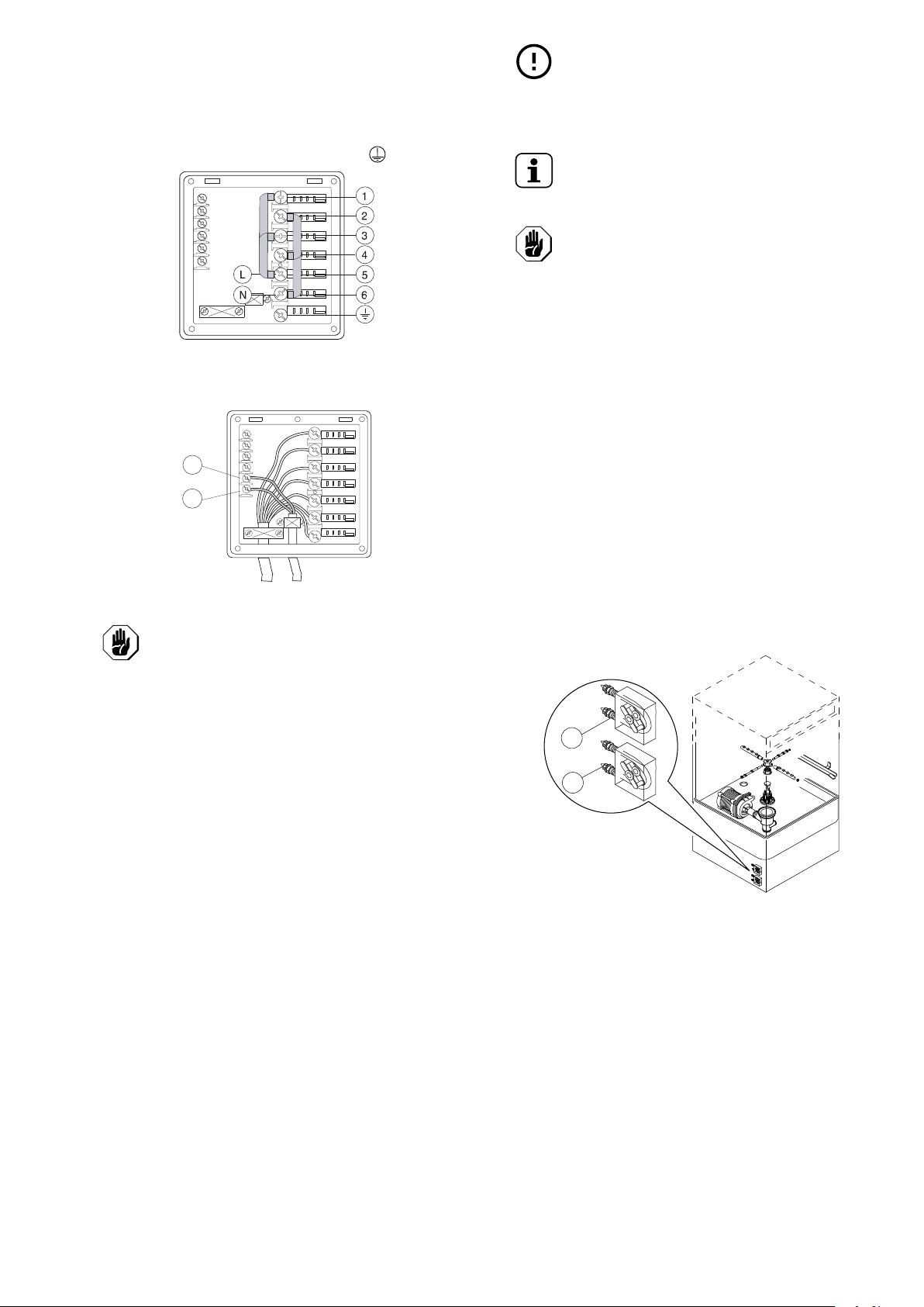
• If the dishwasher is installed on a special support (eg.: work
plan), follow these steps:
1. Accessing the appliance bottom panel and unscrew the
4 feet.
2. Make 4 holes ⌀= 9 mm on the support respecting the
distances shown in the figure below.
3. Put the dishwasher on the support by matching the
holes just made with the seats of the feet in the
appliance bottom panel (see following figure).
4. Fix the dishwasher steadily using screws M8.
E.5 Disposal of packing
The packing must be disposed of in compliance with the
current regulations in the country where the appliance is used.
All the packing materials are environmentally friendly.
They can be safely kept, recycled or burned in an appropriate
waste incineration plant. Recyclable plastic parts are marked
as follows:
Polyethylene
• Outer wrapping
• Instructions bag
Polypropylene
• Straps
Polystyrene foam
• Corner protectors
The parts in wood and cardboard can be disposed of,
respecting the current regulations in the country where the
machine is used.
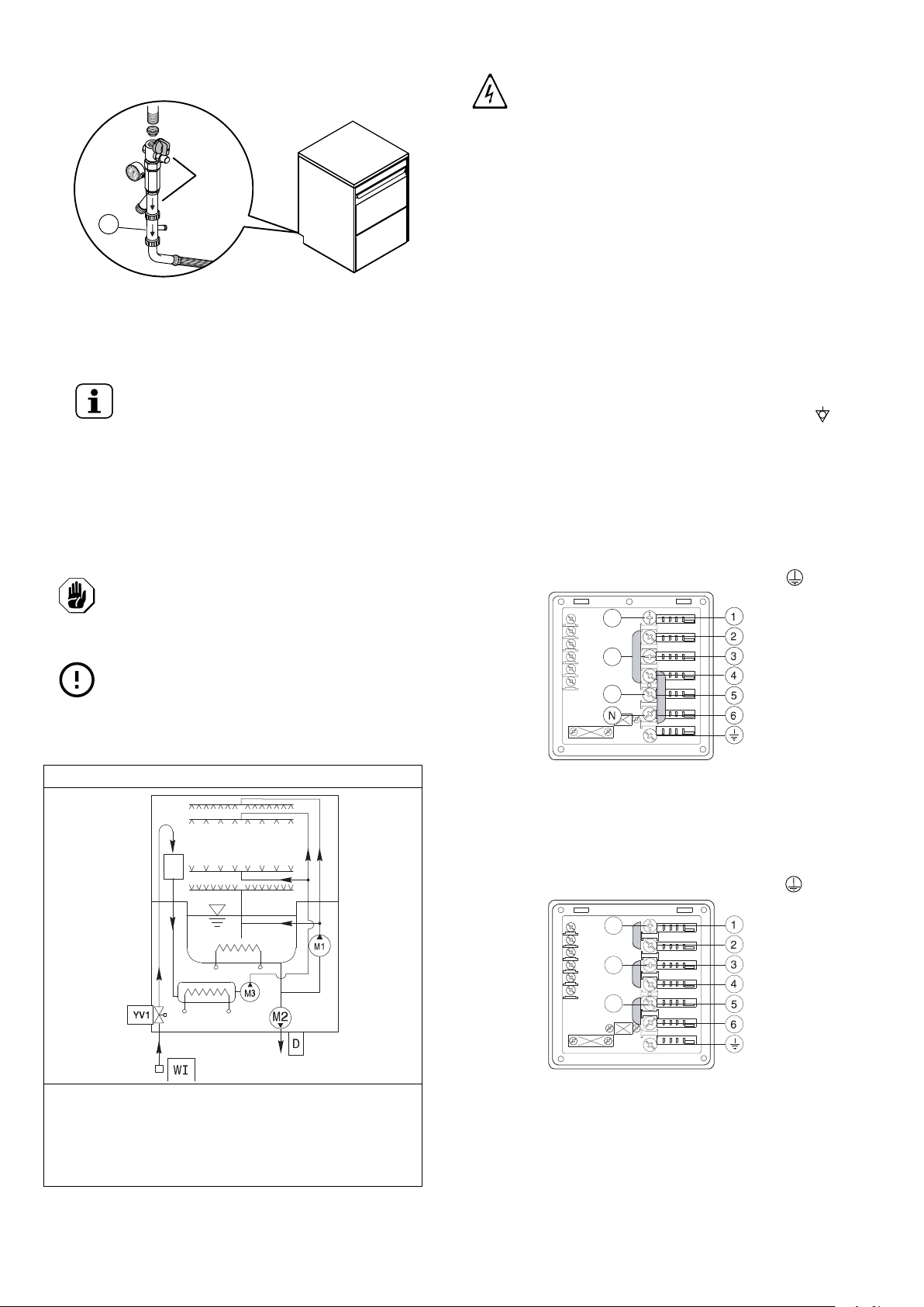
E.6 Plumbing connections
• Connect the appliance water supply pipe “WI“ (see the
Installation diagram) to the mains, fitting a cut-off tap, the
filter provided and a pressure gauge between the appliance
and the mains (see figure below).
x4
870
431 mm
508 mm
14
• In models with incorporated water softener and in some
specific models, connect the double non-return valve “B“
supplied and the machine supply pipe (see figure below).
• Check that the dynamic water supply pressure, measured
between the appliance and the main, is between 200 and
300 kPa for machines with pressure boiler and between 50
and 700 kPa for machines with atmospheric boiler (test
while dishwasher tank or boiler is filling with water).
NOTE!
If the pressure is too high, fit a suitable pressure
reducer on the inlet pipe.
– On the model with free-fall drainage:
connect the waste outlet pipe (detail “D“ in the Installa-
tion diagram) to the main drain pipe, fitting a trap, or
place the outlet pipe over an “S“ trap set into the floor.
– On the model with drain pump:
position the outlet pipe at a height anywhere between
750 and 1000 mm from the floor. Check that about 3 litres
of water flow out of the outlet pipe during the rinse cycle.
CAUTION
Always use a new set of joints if you
remove and reinstall the water inlet pipe to
the appliance.
IMPORTANT
Watermark labelled appliances must be installed in
accordance with AS/NZS 3500.1 and drainage to
be in accordance with 3500.2.
E.7 Plumbing circuits
Appliance with atmospheric water supply - with drain pump
LEGEND
WI = Water inlet
D = Drain
M1 = Wash pump
M2 = Drain pump
M3 = Rinse pump
AG = Air Gap
YV1 = Filling solenoid valve
E.8 Electrical connections
WARNING
Work on the electrical systems
must only be carried out by a
specialised personnel.
• Connection to the power supply must be carried out in
compliance with the regulations and provisions in force in
the country of use.
• Make sure the machine power supply voltage specified on
the rating plate matches the mains voltage.
• Make sure the system power supply is arranged and able to
take the actual current load and that it is executed in a
workmanlike manner according to the regulations in force in
the country of use.
• The earth wire from the terminal board side must be longer
(max 20 mm) than the phase wires.
• Connect the power cable earth wire to an efficient earth.
The equipment must also be included in an equipotential
system, whose connection is made by means of screw EQ
(see par. Installation diagram) indicated by the symbol .
The equipotential wire must have a section of at least 10
mm2.
Power supply 380-415V 3N
Open the power supply terminal board and insert the jumpers
provided as follows: one jumper between terminals 2 and 4
and another between terminals 4 and 6. Using a suitable
power supply cable (see C.1 Main technical characteristics
table), connect the three phases to terminals 1, 3 and 5, the
neutral to terminal 6 and the earth wire to the terminal .
Power supply 220 - 230V 3
Open the power supply terminal board and insert the jumpers
provided as follows: one jumper between terminals 1 and 2,
one between terminals 3 and 4 and another between terminals
5 and 6. Using a suitable power supply cable (see C.1 Main
technical characteristics table) connect the three phases to
terminals 1, 3 and 5 and the earth wire to the terminal .
!
B
A G
L1
L2
L3
L1
L2
L3
15
Power supply 220 - 230V 1N
Open the power supply terminal board and insert the jumpers
provided as follows: two jumpers between terminals 1, 3, 5 and
another two between terminals 2, 4 and 6. Using a suitable
power supply cable (see C.1 Main technical characteristics
table), connect the phase and neutral to terminals 5 and 6
respectively and the earth wire to the terminal .
E.8.1 Connections provided for energy control
This appliance is designed for an external energy consumption
control.
Connect the energy peak controller across terminals 11 and 12.
CAUTION
A normally open (n. o.) contact of the
controller must be connected across ter-
minals 11 and 12. When this contact
closes the boiler heating elements are
disconnected. Using the dishwasher in
these conditions may increase the cycle
time.
E.9 Safety devices
• An automatic-reset overload protector incorporated in the
electric pump windings cuts off the power to the pump in
case of faulty operation.
• A device prevents the booster water from returning back
into the system in the event of a water supply system fault.
• An overflow pipe connected to the discharge ensures a
constant water level in the tank.
• If the water level in the tank is too high, the drain pump (if
present) automatically activates to empty out the excess
water.
IMPORTANT
The Manufacturer declines any liability if the
accident-prevention regulations are not respected.
E.10 Detergent/rinse aid dispensers and
prearrangements
NOTE!
If the machine is connected to a water softener
and/or a reverse osmosis system, contact the
detergent supplier for a specific product.
CAUTION
The peristaltic dispensers (detergent and
rinse-aid) and the tube inside the rinse-aid
dispenser require periodical maintenance
(at least once or twice a year) or after
prolonged machine idle periods.
1. Dishwasher with incorporated liquid detergent dis-
penser (Fig. 1)
The pump “R“ delivers about 0.9 g/s of detergent. At the
first water filling of the day it delivers approx. 44 g of
detergent in 45 seconds, to obtain a concentration of 2g/l.
At each cycle the pump “R“ delivers approx. 6 g in 6 sec.
Dispenser operation time can be modified according to the
instructions given in the next paragraph (G.2 Setting the
dispensers).
Insert the hose supplied in the detergent container
2. Dishwashers with incorporated peristaltic rinse-aid
dispenser pump (Fig. 1)
The pump “S“ dispenses about 0.1 g/s of rinse-aid. It
dispenses 0.3 g in 3 sec. at each rinse.
Dispenser operating time may be changed, following the
instructions given in the next paragraph (G.2 Setting the
dispensers).
Insert the hose supplied in the rinse-aid container.
Fig. 1 Automatic dispenser overview
11
12
S
R

16
F COMMISSIONING
F.1 Preliminary checks, adjustments and
operational tests
WARNING
These operations must only be
carried out by specialized techni-
cians provided with adequate
personal protection equipment
(e. g. safety footwear, gloves,
glasses, etc.), tools and suitable
ancillary equipment with the
appliance switched off and cold.
Electrical and plumbing checks
Before starting the machine:
• check correct connection of the electrical wires that feed the
machine;
• make sure the power supply voltage and frequency match
the data given in the technical data table (C.1 Main
technical characteristics);
• check correct connection of the water supply and drain
pipes (see paragraph E.6 Plumbing connections);
• make sure all the guards, safety devices and emergency
switches are in place and efficient.
Check the positioning of tank components
• Make sure that, the overflow “A“, the tank filter “B“, and the
flat filters “C“ are correctly fitted.
• Make sure the upper and lower wash and rinse arms are
correctly fitted.
G BEFORE FIRST USE
G.1 Manual activation
NOTE!
To obtain excellence washing performance, use
detergent, rinse aid and descaling agent sug-
gested by Electrolux Professional. In the Electrolux
Professional web site, open the “Accessories and
Consumables“ web page and navigate into the
dishwashing equipment tab to order most suitable
detergents and accessories.
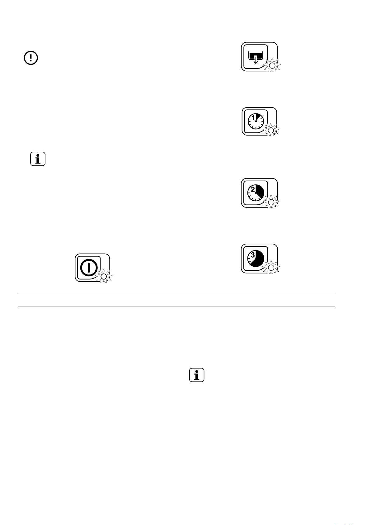
Whenever the detergent containers are replaced, it may be
necessary to activate the dispensers manually in order to fill
the hoses and eliminate any air. Simultaneously press the
buttons, as shown in the figures below. If necessary, repeat
this operation several times.
Detergent dispenser
Rinse-aid dispenser
G.2 Setting the dispensers
All the operations must be carried out with the machine
switched on, the door open and no cycle selected.
Legend
Increase
Decrease
Confirm or select next parameter
A
B
C
C
1
2
3
1
2
3

17
G.2.1 Peristaltic dispenser
Sequential start
1. Press the indicated buttons simultaneously for 5 seconds:
2. Display of programming mode:
3. Initial amount of detergent:
4. Setting the activation time:
5. Initial amount of rinse-aid:
6. Setting the activation time:
7. Amount of detergent during the cycle:
8. Setting the activation time:
9. Amount of rinse-aid during the cycle:
10.Setting the activation time:
11. Exit from programming mode:
H GENERAL SAFETY RULES
H.1 Introduction
The machines are provided with electric and/or mechanical
safety devices for protecting workers and the machine itself.
Therefore the user must not remove or tamper with such
devices.
The Manufacturer declines any liability for damage due to
tampering or their non-use.
H.2 Guards
The guards on the machine are:
• fixed guards (e.g. casings, covers, side panels, etc.), fixed
to the machine and/or frame with screws or quick-release
connectors that can only be removed or opened with tools;
• interlocked movable guards (door) for access inside the
machine;
• machine electrical equipment access doors, made from
hinged panels openable with tools. The door must not be
opened when the machine is connected to the power supply.
WARNING
Several illustrations in the
manual show the machine, or
parts of it, without guards or with
guards removed. This is purely
for explanatory purposes. Do not
use the machine without the
guards or with the protection
devices deactivated.
H.3 Safety signs to be placed on the
machine or near its area
Prohibition Meaning
do not oil, lubricate, repair and adjust
moving parts
do not remove the safety devices
do not use water to extinguish fires
(placed on electrical parts)
1
1
2
3
1
2
3
1
2
3
1
2
3
1
2
3

18
Danger Meaning
danger of crushing hands
caution hot surface
danger of electrocution (shown on elec-
trical parts with indication of voltage)
WARNING
Do not remove, tamper with or
make illegible the safety, danger
and instruction signs and labels
on the machine.
H.4 Instructions for use and maintenance
Risks mainly of a mechanical, thermal and electrical nature
exist in the machine. Where possible the risks have been
neutralised:
• directly, by means of adequate design solutions.
• indirectly by using guards, protection and safety devices.
Any anomalous situations are signalled on the control panel
display.
During maintenance several risks remain, as these could not
be eliminated, and must be neutralised by adopting specific
measures and precautions.
Do not carry out any checking, cleaning, repair or maintenance
operations on moving parts. Workers must be informed of this
prohibition by means of clearly visible signs.
To guarantee machine efficiency and correct operation,
periodical maintenance must be carried out according to the
instructions given in this manual.
Make sure to periodically check correct operation of all the
safety devices and the insulation of electrical cables, which
must be replaced if damaged.
WARNING
Extraordinary machine mainte-
nance operations must only be
carried out by specialised per-
sonnel provided with all the
appropriate personal protection
equipment (safety shoes, gloves,
glasses, overalls, etc.), tools,
utensils and ancillary means.
WARNING
Never operate the machine,
removing, modifying or tamper-
ing with the guards, protection or
safety devices.
Before carrying out any opera-
tion on the machine, always
consult the manual, which gives
the correct procedures and con-
tains important information on
safety.
H.5 Reasonably foreseeable improper use
Improper use is any use different from that specified in this
manual. During machine operation, other types of work or
activities deemed improper and that in general can involve
risks for the safety of operators and damage to the appliance
are not allowed. Reasonably foreseeable improper use
includes:
• lack of machine maintenance, cleaning and periodical
checks;
• structural changes or modifications to the operating logic;
• tampering with the guards or safety devices;
• failure to use personal protection equipment by operators,
specialised personnel and maintenance personnel;
• failure to use suitable accessories (e.g. use of unsuitable
equipment or ladders);
• keeping combustible or flammable materials, or in any case
materials not compatible with or pertinent to the work, near
the machine;
• wrong machine installation;
• placing in the machine any objects or things not compatible
with its use, or that can damage the machine, cause injury
or pollute the environment;
• climbing on the machine;
• non-compliance with the requirements for correct machine
use;
• other actions that give rise to risks not eliminable by the
Manufacturer.
WARNING
The previously described actions
are prohibited!
H.6 Residual risks
The machine has several risks that were not completely
eliminated from a design standpoint or with the installation of
adequate protection devices. Nevertheless, through this
manual the Manufacturer has taken steps to inform operators
of such risks, carefully indicating the personal protection
equipment to be used by them. In order to reduce the risks,
provide for sufficient spaces while installing the unit. To
preserve these conditions, the areas around the machine
must always be:
• kept free of obstacles (e.g. ladders, tools, containers, boxes,
etc.);
• clean and dry;
• well lit.
For the Customer's complete information, the residual risks
remaining on the machine are indicated below: such situations
are deemed improper and therefore strictly forbidden.

19
Residual risk Description of hazardous
situation
Slipping or falling The operator can slip due to water
or dirt on the floor
Catching, dragging or
crushing
Catching or dragging of the oper-
ator or other persons in the drive,
during the machine work phase,
due to improper actions, such as:
• placing an arm inside the
machine to remove a stuck rack
without stopping the machine
by operating an emergency
switch;
• accessing the rack handling
system without stopping the
machine by operating an emer-
gency switch.
Use of improper clothing with
loose parts (e.g. necklaces,
scarves, shawls, ties, etc.) or long
hair not gathered, which could get
caught up in moving parts.
Burns/abrasions (e.g.
heating elements,
cold pan, cooling cir-
cuit plates and pipes)
The operator deliberately or unin-
tentionally touches some
components inside the machine
without using protective gloves.
Stab wounds The operator deliberately or unin-
tentionally touches some
components with sharp edges
during the machine cleaning with-
out using protective gloves.
Burns The operator deliberately or unin-
tentionally touches some
components inside the machine or
dishes at the outfeed without using
gloves or without allowing them to
cool.
Residual risk Description of hazardous
situation
Shearing of upper
limbs
The operator violently closes the
front panels.
Electrocution Contact with live parts during
maintenance operations carried
out with the electrical panel
powered
Falling from above The operator intervenes on the
machine using unsuitable systems
to access the upper part (e.g. rung
ladders, or climbs on it)
Crushing or injury The specialised personnel may
not correctly fix the control panel
when accessing the technical
compartment. The panel could
close suddenly.
Crushing or shearing Possible risk of injury to upper
limbs during the hood closing
operation.
Tipping of loads When handling the machine or the
packing containing it, using unsuit-
able lifting systems or accessories
or with the unbalanced load
Chemical Contact with chemical substances
(e.g. detergent, rinse aid, scale
remover, etc.) without taking
adequate safety precautions.
Therefore always refer to the
safety cards and labels on the
products used.
IMPORTANT
In case of a significant anomaly (e.g. short circuits,
wires coming out of the terminal block, motor
breakdowns, worn electrical cable sheathing, etc.)
the operator must immediately deactivate the
machine.
I CONTROL PANEL
I.1 Control panel description
1On/Off
2Drain/self-cleaning cycle
3Display
4Tank temperature indicator
5Boiler temperature indicator
6Wash cycle 1
7Wash cycle 2
8Wash cycle 3
9Wash Safe Control
1 2
3
6
7 8 94
5
1 2
3
6
7 8 94
5
1 2 3 6 74
5
20
The temperature shown on the display refers to the boiler if the
indicator “5“ is lit up or to the tank, if the indicator “4“ is lit up.
The tank temperature is displayed during the wash phase and
the boiler temperature during the rinse phase.
IMPORTANT
The “guaranteed rinse system“ (GRS) is incorpo-
rated in the WASH SAFE CONTROL (see indicator
light “9“). The “guaranteed rinse system“ is an
automatic rinse time/ temperature control system.
Operation is as follows:
• during the wash cycle the indicator light is OFF;
• during the rinse cycle the indicator light comes on and is
GREEN;
• at the end of the rinse cycle the indicator light remains
GREEN if the rinse temperature and time have been carried
out as per the programme, otherwise the indicator light
becomes RED;
• upon opening the door, the indicator light GOES OUT.
NOTE!
If the indicator light becomes RED, for example
should the boiler waiting time be disabled, wait
for a couple of minutes and then repeat the
wash cycle.
I.2 Basic Controls
Described below are all the single buttons and functions
available in the various control panel models listed above.
Some functions are common to all models of the range,
whereas others are available only on some versions.
On/Off
This button indicates equipment status: on or off. When the
equipment is on, the button indicator is lit up.
Drain / self-cleaning cycle
This button starts a drain/self-cleaning cycle. When the cycle is
selected, the button indicator is lit up.
Wash cycle 1
This button starts Wash cycle 1. When the cycle is selected,
the button indicator is lit up. This cycle is recommended for
washing glasses.
Wash cycle 2
This button starts Wash cycle 2. When the cycle is selected,
the button indicator is lit up. This cycle is recommended for
washing very dirty dishes. This cycle is recommended for
washing lightly or normally dirty dishes.
Wash cycle 3
This button starts Wash cycle 3. When the cycle is selected,
the button indicator is lit up. This cycle is recommended for
washing very dirty dishes.
J NORMAL MACHINE USE
J.1 Foreseen use
Our appliances are designed and optimised to ensure high
performance and efficiency. This equipment must only be used
for its expressly designed purpose, i. e. washing dishes with
water and specific detergents. Any other use is deemed
improper.
This appliance does not carry out the rinse cycle should there
be no supply water; it stops all functions with an error message
“A1“ (also see Alarms).
J.2 Operator qualified for normal machine
use
Must have at least:
• knowledge of the technology and specific experience in
operating the machine;
• adequate general basic education and technical knowledge
for reading and understanding the contents of the manual,
including correct interpretation of the drawings, signs and
pictograms;
• sufficient technical knowledge for safely performing his
duties as specified in the manual;
• knowledge of the regulations on work hygiene and safety.
In case of a significant anomaly (e. g. short circuits, wires
coming out of the terminal block, motor breakdowns, worn
electrical cable sheathing, etc.) the operator for normal
machine use must:
• immediately deactivate the machine by turning the switch
disconnector to “O“ or operating the main emergency switch
on the equipment;
• close the machine water supply by shutting off the water.
J.3 Starting
NOTE!
Carry out a couple of cycles without dishes to flush
out any industrial grease which has remained in
the tank and piping.
• Open the water supply tap.
• Switch on at the mains.
• Open the door and check that all the components are in
their correct position.
This manual suits for next models
3
Table of contents
Other Electrolux Professional Dishwasher manuals


