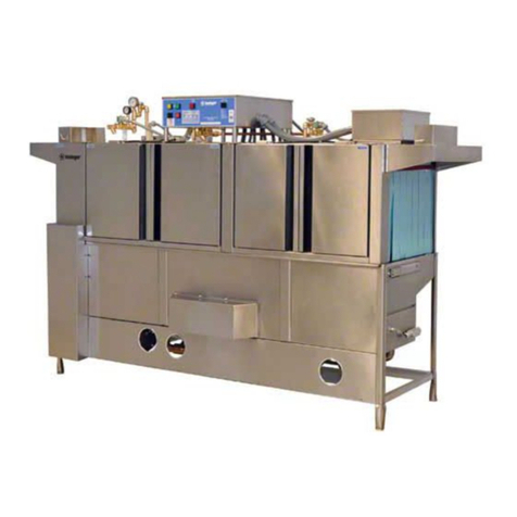
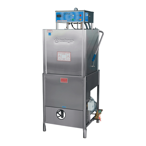
manuals.online logo
Brands
  1. Home
  2. •
  3. Brands
  4. •
  5. Insinger
  6. •
  7. Dishwasher
  8. •
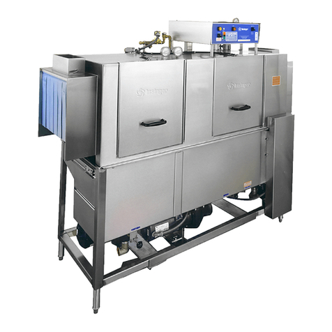
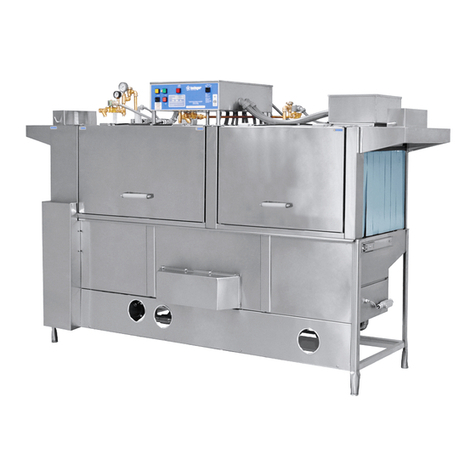
  9. Insinger SPEEDER 64 User manual

Insinger SPEEDER 64 User manual

TECHNICAL MANUAL
Installation, Operation and Maintenance Instructions
RACK CONVEYOR
DISHWASHERS
Speeder 64
Speeder 86
Super 106
Insinger Machine Company
6245 State Road
Philadelphia, PA 19135-2996
800-344-4802
Fax: 215-624-6966
www.insingermachine.com
~Jlnsinger
Super Speeder Tech Manual 6_2015 www.insingermachine.com 800-344-4802
Thank you for purchasing this quality
Insinger product.
On the space provided below please record the
model, serial number and start-up date of this unit:
Model:__________________________________
Serial Number:___________________________
Start-Up Date:____________________________
When referring to this equipment please have this
information available.
Each piece of equipment at Insinger is carefully
tested before shipment for proper operation. If the
need for service should arise please contact your
local Authorized Insinger Service Company.
A Service Network Listing is provided on our web
site, www.insingermachine.com or call Insinger at
800-344-4802 for your local authorized servicer.
For proper activation of the Insinger Limited
Warranty a SureFire™ Start-Up & Check-Out Service
should be completed on your machine. Refer to the
Introduction section in this manual for an explanation
of Insinger SureFire™ Start-Up & Check-Out
Program.
Please read the Insinger Limited Warranty and all
installation and operation instructions carefully before
attempting to install or operate your new Insinger
product.
To register your machine for warranty by phone, fax
or the internet or for answers to question concerning
installation, operation, or service contact our
Technical Services Department:
TECHNICAL SERVICE CONTACTS
Toll-Free 800-344-4802
Fax 215-624-6966
e-mail [email protected]
Web site www.insingermachine.com
TABLE OF CONTENTS
Part 1
Technical Information
Catalog Specication Sheet
Introduction
Warranty
Part 2
Installation & Operation Instructions
Part 3
Maintenance and Repair Procedures
Part 4
Electrical Schematics & Electrical Replacement
Parts
Part 5
Replacement Parts
~Jlnsinger
RACK CONVEYOR SERIES
TECH
MANUAL.
INTRODUCTION
Part
1,
Section A
I.A
INTRODUCTION
·
1.A.l Purpose
The purpose
of
this Tech Manual is to provide installation, operation, cleaning and maintenance
directions. A section is provided for replacement parts.
l.A.2 Scope
Thismanualcontains allpertinentinformationto assistintheproperinstallation,operation,cleaning,
maintenance, and parts ordering for lnsinger Rack Conveyor Dishwasher Series including the
Admiral, Speeder and Super models.
The installation instructions are intended for qualified equipment installers. The operation and
cleani~g instructi~ons
&,e
'intended t9r the
d~y
users
of
the equipment. The maintenance.:
a1:1d
parts sections are intended for qualified service and/or maintenance technicians.
Replacementpartsmay beordereddirectly from ourfactory orfrom yourlocalInsingerAuthorized
Service Agency. Forthe name
of
your local Insinger Authorized Service Agency pleas'e reference
the Service Network Listing in Section 1
of
this manual. You can also speak to the Insinger
Technical Services Department, 800/344-4802, or e-mail us at [email protected].
When calling
for
warranty information or replacement parts please provide the model and serial
number
of
your Insinger equipment. These important numbers should be noted inthis manual on
the spaces provided on the opening page.
'1.A.3 Surefire™ Start-up & Check-out Program
Insingerisproudto offerourexclusive Surefire™ Start-up &Check-outProgramto ourcommercial
customers. 1bisservice is included inthepurchase price
of
your newInsinger dishwasher.
We
will
provide an authorized factory service technician for the initial start-up
of
your new Insinger
dishwasher to ensure
it
is running correctly. Please call the factory or your local Insinger Sales
Representative to schedule this service.
t
1.A.4 Definitions
, • I
Thr6ughoutthis guideyouwill find the following terms: WARNING, CAUTION, & NOTE. When
used, these terms will be outlined
in
a box to draw attention:
rlsd:
12/97,
6/98
s:\wp5l\manual\admiral
WARNING
indicates potential physical danger.
CAUTION indicates potential equipment damage.
NOTE indicates helpful operating hints ortips.
CSI - 11400
Approval
Date
Project
Item
Quantity
Speeder 64
Double Tank Rack Conveyor Dishwasher
6245 State Road ∙ Philadelphia, PA 19135 ∙ PH: 800-344-4802 ∙ FX: 215-624-6966 ∙ www.in sing erma ch ine. com
Automatic conveyor, rack type, double tank
dishwasher with recirculating wash and rinse and
fresh water final rinse
0.52 gallons/rack final rinse consumption
Capacity is 277 (20” x 20”) racks per hour or 6,925
dishes per hour
Error proof replacement with color-coded curtains
STANDARD FEATURES
CrossFire Wash System
Color-coded curtains
Tank heat:
Electric immersion heater
Steam injector
Capillary thermometers for wash and rinse
In-line thermometer for final rinse
Vacuum breaker on all incoming water lines
Manifold clean-out brush
SureFire Start-Up & Check-Out Service
Inspection door
Ventilation fan connection provision
S/S frame, legs and feet
S/S front enclosure panel
Automatic tank fill
Low water protection
Detergent connection provision
Elevated top mounted NEMA 12 control panel
Easily-cleaned crowned hood top
Simplified scrap screen design
Door safety switch
Standard frame drip proof motors
Energy saver
Override switch for deliming
End caps/pipe plugs secured to prevent loss
Timing belt conveyor drive
OPTIONS
Stainless steel steam coil tank heat
Steam booster
Electric booster
Single point electrical connection: motors, controls and
tank heat. (Booster requires a separate connection)
End cowls with vent and adjustable damper controls
S/S splash guards
Security package
Totally enclosed motors
Rack limit switch
Power Loader
Power Unloader
Door activated drain closers
Insulated hood and door
Plastic 20” x 20” racks (plate or silver)
CrossFire Wash System power
sprays water horizontally, as
well as, from above and below,
cleaning and sanitizing the
dirtiest of ware.
SPECIFIER STATEMENT
Specified unit will be an Insinger Speeder 64 double tank rack conveyor
dishwasher. Features include CrossFire Wash System, capillary
thermometer for wash and rinse, in-line thermometer for final rinse,
vacuum breaker, SureFire Start-Up & Check-Out service, inspection
door automatic tank fill, low water protection, door safety switch, energy
saver, timing belt conveyor drive, and 304 stainless steel construction.
~Jlnsinger
Note: Due to product improvement we reserve the right to
change information and specifications without notice.
6245 State Road ∙ Philadelphia, PA 19135 ∙ PH: 800-344-4802 ∙ FX: 215-624-6966 ∙ www.in sing erma ch ine. com
Additional Information
SPECIFICATIONS
CONSTRUCTION- Hood and tank constructed of 16 gauge type 304
S/S. Hood unit of all welded seamless construction. S/S frame, legs
and feet. All internal castings are non-corrosive lead free nickel alloy,
bronze or S/S.
DOORS- Extra large die formed 18-8 type 304 S/S front inspection
door riding in all S/S channels. A triple ply leading edge on the door
channels made of S/S with no plastic or nylon sleeves or liners used.
Two intermediate S/S door safety stops on door.
CONVEYORS- One S/S roller chain conveyor, with rack driving
lugs every sixth link, running along the front of the machine. Eleven
free spinning rollers placed along the back wall of the machine.
Conveyor accommodates all standard 20” racks. Conveyor drive
system includes direct drive gear motor with frictionless, trouble-free
clutch system, spring-loaded and automatically re-engaging. Racks
conveyed automatically through washing and rinsing systems,
powered by an independent 1/15 hp drive motor.
PUMP- Centrifugal type “packless” pump with a brass petcock
drains. Construction includes ceramic seal and a balanced cast
impeller on a precision ground stainless steel shaft, extension or
sleeve. All working parts mounted as an assembly and removable
as a unit without disturbing pump housing. 1 hp motor for each
wash and rinse pump: standard horizontal C-face frame, drip proof,
internally cooled with ball-bearing construction.
CONTROLS- Top mounted NEMA 12 control enclosure, with 3.5
inch air gap between hood and enclosure, housing motor overload
protection, contactors, transformers and all other dishwasher
controls. All controls safe low voltage 24 VAC.
ENERGY SAVER- Rack actuated lever automatically operates the
final rinse solenoid only when a rack passes, saving water and
energy. The lever also activates an adjustable timer control. If no
ware passes during the set time, the machine shuts down.
SPRAY SYSTEM- Spray arms made of type 304 stainless steel pipe.
Spray assemblies removable without the use of tools.
WASH- Upper and lower manifolds with the patented CrossFire®
Wash System. One manifold above with 3 power wash arms, each
with 9 high pressure cleaning slots and one manifold below with 3
power wash arms, each with 9 high pressure cleaning slots. The
slots are precision milled for water control producing a fan spray.
Wash arms are fillet welded to the S/S manifold. The CrossFire®
Wash System provides 4 horizontally spraying high pressure nozzles.
RINSE- Upper and lower manifolds. One manifold above with 3
power rinse arms, each with 9 high pressure rinsing slots and one
manifold below with 3 power rinse arms, each with 9 high pressure
rinsing slots. The slots are precision milled for water control
producing a fan spray. Rinse arms are fillet welded to the S/S
manifold.
FINAL RINSE- Six nozzles above and three nozzles below threaded
into S/S schedule 40 pipes. Nozzle assemblies produce a fan spray
reducing water consumption, maximizing heat retention.
DRAIN- Drain valve externally controlled. Overflow assembly with
skimmer cap is removable without the use of tools for drain line
inspection. Heater is protected by low water level control.
Note: Exhaust requirements are for pant leg connections only. For
hood type, CFM requirements vary, consult hood manufacturer for
specific sizing.
Capacity Per Hour 277 racks
6925 dishes
300-600 meals
Tank Capacity 12 gals. (wash) 13 gals. (rinse)
25.5 gals. (gas wash)
26 gals. (gas rinse)
Motor Size 1 hp (wash) 1 hp (rinse)
1/15 hp (conveyor)
Electric Usage 7.5 kW wash tank
15 kW rinse tank
15 kW booster 40° rise
27 kW booster 70° rise
Gas Consumption 90,000 BTUH
88 CFH nat. gas
36 CFH propane
Steam Consumption
at 20 psi min.
81 lbs./hour tank
51 lbs./hour booster 40° rise
90 lbs./hour booster 70° rise
Final Rinse Peak Flow
at 20 psi min.
2.4 gallons/minute
Final Rinse Consumption at
20 psi min.
144 gallons/hour
0.52 gallons/rack
Exhaust Hood Requirement 350 CFM Load
350 CFM unload
Peak Rate Drain Flow 14 gallons/minute
Installation distance from
vertical combustible service
2"
Shipping Weight 800 lbs.
Machine Electrical
Motors, Controls, Tank
Heat Steam Gas Electric
240/1/60
208/3/60
240/3/60
480/3/60
380/3/50
9.7
10.7
9.8
4.9
5.9
20.2
11.9
10.9
5.4
6.6
112.8
73.1
63.9
31.9
40.0
Technical Drawings
Ol/ERALL
LENGTH
64"
~~~
1, @-j
.L....LJe
~
1 r
t.
OPe/lNG
I '---
t.
DISHWASHER
RIM
ROLL
T§
;._
lE
~::j
"'~
• r '
l~
-rl
*
c:::::J
TYPICAL
TABLE
CONNECTION
H
14·
1
I
6.J.1/2~~
28 .J/4 4
-~~~·~,~
J'"
I
...
,_
f
~~
I
-~
__,
~~
__,
SEE
NOTE:
137
I I I l I I I [
Sff
NOTE:
#.J
I1
I I
~
~
0
~
..,
"'
"
.,
I
"'
"
~~I
.,-
..,
s.
I
~L,
;.i;
"'
L1
""
......
~
I!
4 ,
♦
~
-
~
-
~
I
!,,_
12
J/4
111
'--7
~
49
--
r_:J
~
~
'"""'~
~-1~i-:r::4.J
=-
JJ
J/4
~~
I
~~
261/2---l
~
2
J/4
~./J
J/4=J-
32
5/16
fNSTALLA
TION
CONNECTIONS
----64
L
TR
DESCRfPTTON
SIZE
Hf
!HOT
WATER
TO
AUTO
ALL
-140' F I
3/4
RPS
H2I
HOT
WATER
TO
ANAL
RINSE
-180' F I
1/2
RPS
HJ
I
HOT
WATER
TO
STEAM
BOOSTER
"' I
1/2
RPS
H4
IHOT
WATER
TO
ELECTRIC
BOOSTER"
I
1/2
RPS
S1
!STEAM
TO
TANKS
-
WASH
I
1/2
RPS
R/GHT
TO
LEFT
FEED
~
1.
VENTS
.t:
ADJUSTABLE
DAMPERS
FURNISHED
0/1/L
Y
YtHEN
SP
ECIFIED.
S2
!STEAM
TO
TANKS
-
RINSE
I
J/4
RPS
SJ
I
STEAM
TO
BOOSTER
I1/ 2 / 1"
FIPS
2.
"J;.'
FOR
HOT
WAIER
TO
BOOSIER
140" F
STD/
110' F
SPECIAL
.
J.
ALLOW
24'
MIN.
CLEARANCE
BELOW
DISHTA8l£
TO
SERVICE
ELECTRICAL
EQUIPMe/T.
D
!DRAIN
CONNECTION
I 2 RPS
R1
CONDENSATE
RETURN
TANK
COILS
1/2
RPS
OVERALL
DIMENSIONS
R2
CONDENSATE
RETURN
BOOSTER
1
/2
RPS
MACHINE
TYPE
LENGTH
E1
ELECTRICAL
SERI/IC£
-
MOTORS
2
1/4
HP
STEAM
-
W/ROOSTER
95
1/2
£2
ELECTRfCAL
SERVICE
-
WASH
7
1/2
KW
ELECT
WmuT
WATER
F.
RINSE
83
1/2
EJ
ELECTRICAL
SERVICE
-
RINSE
15
KW
ELECTRIC
HEAT
W/BOOSTER
103
£4
ELECTRfCAL
SERVICE
-
BOOSTER
24/45
KW
STEAM
-
WITHOUT
BOOSTER
83 1
/2
INSTALLATION
AND
LAYOUT
DETAIL
r25
7/Bl
r
ii
;;~
~
~
~8
:,:~
~
;:\;;!
1j
~
•
21
~Qi:
~
OPe/lNG
8£TWITN
TRACKS
Information
and
Speci
fications
Subject to Chanqe Without Notice.
SPEEDER
64
DOUBLE
TANK
CC:W.ot:W TYP£
DISHWASHER
I • P
hDadelp
l\
la.
PA 191J5
n
singer
rA~21~562~~66
DR'IIN,
EW
12.29.99
SCALE
DOC.
NO.
REV:_
1<911
__
01
.29.
0ll
1
/Z'
= 1•
SP-64R
REV
K
Technical Drawings
INSTALLATION
AND
LAYOUT
DETAIL
h
~~
-::;1
-~
.,
~
c:,
IGTH
(SEE
_CHART)!
~
BETWEEN
TABLES
64"·
.
it'.
OPENING
-="
I
t,
T
f
DISHWASHER
J
i~~~
--
~
r25
7/8
7
I
~l
1•
~
11/81:
·1
~
-
l
·14
1
18
:J/4
F~
,
1/8:__=----,
?111
rSEENOTEl7
...
OPENING
BETWEEN
11?ACKS
II
8
~~
~
t!i~
d~
•
al
&l
<>:
t!
SIT
NOTE
/J
•i)
~
<=>
I
:
~!=1
1 i
~
1
I '~j
-+-
1---b
I j
.,
~
--+-
...
-
~
INSTALLATION
CONNECTIONS
ILTRI
DESCRIPTION
I
SIZE
HI
HOT
WATER
TO
A
7i
FILL
-
140°
F 3
'4
RP
H2
HOT
WATER
TO
FINAL
RINSE
-
180°
F 1
'2
FIPS
H3
HOT
WATER
TO
STEAM
BOOSTER
" 1
'2
FIPS
H4
IHOT
WATER
TO
ELECTRIC
BOOSTER"
I
1/2
FIPS
S1
ISTEAM
TO
TANKS
-
WASH
I
1/2
FIPS
S2
,STEAM
TO
TANKS
-
RINSE
I
31
RPS
S3
STEAM
_
TO
BOOSTER
______
1/ 2 _
I"
Rf'S
D I
DRAIN
CONNECTION
I
~
FIPS
RI
CONDENSATE
RETURN
-
TANK
COILS
1;
FIPS
R2
I
CONDENSATE
RETURN
-
BOOSTER
I
1/2
FIPS
ET
ltircm1cAL
SERvict -
MdidRs
I 2
1/4
HP
E2
I
ELECTRICAL
SER
1/TCE
-
WASH
HEAT
I 7 172
KW
E3
I
ELECTRICAL
SER
1/TCE
-
RINSE
HEA
T I
15
KW
£4
!ELECTRICAL
SERI/TC£
-
BOOSTER
I
24/45
KW
·:J.J
3/4
j " -
49~
I
B~
32
5/16
/4~,r.,.
_I
64
60
1(4
----yr.,--,
LEFT
TO
RIGHT
FEED
.tfJllI::i;_
1.
VENT
,i-
ADJUSTABLE
DAMPERS
FURNISHED
ONLY
'MIEN
SPECIFIED.
2.
"t,,"
FOR
HOT
WAJE1?
TO
BOOSJE1?
140"
F
STD/
110• F
=CJAL.
:J. ALLOW 2'1"
MIN.
CLEARANCE BELOW 0/SHTABI.£
TO
SERVICE
ELECTRICAL
EQUIPMENT.
OVERALL
DIMENSIONS
MACHIN
E
TYPE
I
LE
NGTH
STEAM
-
OSTER
ELECT.
W R
F.
RINSE
ELECTRIC
OOSTER
STEAM
-
OOSTER
"'
"'
,__
~
~
::J
I
c:,
S-
"
.,
l
.:;
I
I
ll
T
~~I
~f]L:-~
2
J/4
~l-15
12
3/4
26
1/2
Information
and
Specificat
i
ons
Subject
to
Chanqe Without Notice.
SPEEDER
64
r.l
DOUBLE
TANK
CXWll£rtW
T'l'PC
OISHWA911NG
11.Aa-HNE
lnsin
ger
Ph
lc';\:~h~~:~
35
FAX
(215) 624--6Q66
OR'IIN,
EJ,/M
12.J0.99
SCALE
DWG.
HO.
REV
RE'r.
KBA1
01.29.
08
t/2"
= 1'
SP
- S4L K
CSI - 11400
Approval
Date
Project
Item
Quantity
Speeder 86
Double Tank Conveyor Dishwasher
with Recirculating Pre-wash
6245 State Road ∙ Philadelphia, PA 19135 ∙ PH: 800-344-4802 ∙ FX: 215-624-6966 ∙ www.in sing erma ch ine. com
Automatic conveyor, rack type, double tank dishwasher
with recirculating pre-wash, wash, rinse and fresh
water final rinse
0.52 gallons/rack final rinse consumption
Capacity is 277 (20” x 20”) racks per hour or 6,925
dishes per hour
Error proof replacement with color-coded curtains
CrossFire Wash System power
sprays water horizontally, as
well as, from above and below,
cleaning and sanitizing the
dirtiest of ware.
STANDARD FEATURES
CrossFire Wash System
Color-coded curtains
Tank heat:
Electric immersion heater
Steam injector
Capillary thermometers for wash and rinse
In-line thermometer for final rinse
Vacuum breaker on all incoming water lines
Manifold clean-out brush
SureFire Start-Up & Check-Out Service
Inspection door
Ventilation fan connection provision
S/S frame, legs and feet
S/S front enclosure panel
Automatic tank fill
Low water protection
Detergent connection provision
Elevated top mounted NEMA 12 control panel
Easily-cleaned crowned hood top
Simplified scrap screen design
Door safety switch
Standard frame drip proof motors
Energy saver
Override switch for deliming
End caps/pipe plugs secured to prevent loss
Timing belt conveyor drive
OPTIONS
Stainless steel steam coil tank heat
Steam booster
Electric booster
Single point electrical connection: motors, controls and
tank heat. (Booster requires a separate connection)
End cowls with vent and adjustable damper controls
S/S splash guards
Security package
Totally enclosed motors
Rack limit switch
Power Loader
Power Unloader
Door activated drain closers
Insulated hood and door
Plastic 20” x 20” racks (plate or silver)
SPECIFIER STATEMENT
Specified unit will be an Insinger Speeder 86 double tank rack conveyor
dishwasher with pre-wash. Features include CrossFire Wash System,
capillary thermometer for wash and rinse, in-line thermometer for final
rinse, vacuum breaker, SureFire Start-Up & Check-Out service, inspection
door automatic tank fill, low water protection, door safety switch, energy
saver, timing belt conveyor drive, and 304 stainless steel construction.
~Jlnsinger
6245 State Road ∙ Philadelphia, PA 19135 ∙ PH: 800-344-4802 ∙ FX: 215-624-6966 ∙ www.in sing erma ch ine. com
Additional Information
SPECIFICATIONS
CONSTRUCTION- Hood and tank constructed of 16 gauge type 304
S/S. Hood unit of all welded seamless construction. S/S frame, legs
and feet. All internal castings are non-corrosive lead free nickel alloy,
bronze or S/S.
DOORS- Extra large die formed 18-8 type 304 S/S front inspection
door riding in all S/S channels. A triple ply leading edge on the door
channels made of S/S with no plastic or nylon sleeves or liners used.
Two intermediate S/S door safety stops on door.
CONVEYORS- One S/S roller chain conveyor, with rack driving
lugs every sixth link, running along the front of the machine. Eleven
free spinning rollers placed along the back wall of the machine.
Conveyor accommodates all standard 20” racks. Conveyor drive
system includes direct drive gear motor with frictionless, trouble-free
clutch system, spring-loaded and automatically re-engaging. Racks
conveyed automatically through washing and rinsing systems,
powered by an independent 1/15 hp drive motor.
PUMP- Centrifugal type “packless” pump with a brass petcock
drains. Construction includes ceramic seal and a balanced cast
impeller on a precision ground stainless steel shaft, extension or
sleeve. All working parts mounted as an assembly and removable
as a unit without disturbing pump housing. 1 hp motor for each
wash and rinse pump: standard horizontal C-face frame, drip proof,
internally cooled with ball-bearing construction.
CONTROLS- Top mounted NEMA 12 control enclosure, with 3.5
inch air gap between hood and enclosure, housing motor overload
protection, contactors, transformers and all other dishwasher
controls. All controls safe low voltage 24 VAC.
ENERGY SAVER- Rack actuated lever automatically operates the
final rinse solenoid only when a rack passes, saving water and
energy. The lever also activates an adjustable timer control. If no
ware passes during the set time, the machine shuts down.
SPRAY SYSTEM- Spray arms made of type 304 stainless steel pipe.
Spray assemblies removable without the use of tools.
WASH- Upper and lower manifolds with the patented CrossFire®
Wash System. One manifold above with 3 power wash arms, each
with 9 high pressure cleaning slots and one manifold below with 3
power wash arms, each with 9 high pressure cleaning slots. The
slots are precision milled for water control producing a fan spray.
Wash arms are fillet welded to the S/S manifold. The CrossFire®
Wash System provides 4 horizontally spraying high pressure nozzles.
RINSE- Upper and lower manifolds. One manifold above with 3
power rinse arms, each with 9 high pressure rinsing slots and one
manifold below with 3 power rinse arms, each with 9 high pressure
rinsing slots. The slots are precision milled for water control
producing a fan spray. Rinse arms are fillet welded to the S/S
manifold.
FINAL RINSE- Six nozzles above and three nozzles below threaded
into S/S schedule 40 pipes. Nozzle assemblies produce a fan spray
reducing water consumption, maximizing heat retention.
DRAIN- Drain valve externally controlled. Overflow assembly with
skimmer cap is removable without the use of tools for drain line
inspection. Heater is protected by low water level control.
Note: Exhaust requirements are for pant leg connections only. For
hood type, CFM requirements vary, consult hood manufacturer for
specific sizing.
Capacity Per Hour 277 racks
6925 dishes
300-600 meals
Tank Capacity 12 gals. (wash) 13 gals. (rinse)
25.5 gals. (gas wash)
26 gals. (gas rinse)
Motor Size 1 hp (wash) 1 hp (rinse)
1/15 hp (conveyor)
Electric Usage 7.5 kW wash tank
15 kW rinse tank
15 kW booster 40° rise
27 kW booster 70° rise
Gas Consumption 90,000 BTUH
88 CFH nat. gas
36 CFH propane
Steam Consumption
at 20 psi min.
81 lbs./hour tank
51 lbs./hour booster 40° rise
90 lbs./hour booster 70° rise
Final Rinse Peak Flow
at 20 psi min.
2.4 gallons/minute
Final Rinse Consumption at
20 psi min.
144 gallons/hour
0.52 gallons/rack
Exhaust Hood Requirement 350 CFM Load
350 CFM unload
Peak Rate Drain Flow 14 gallons/minute
Installation distance from
vertical combustible service
2"
Shipping Weight 1200 lbs.
Machine Electrical
Motors, Controls, Tank
Heat Steam Gas Electric
240/1/60
208/3/60
240/3/60
480/3/60
380/3/50
9.7
10.7
9.8
4.9
5.9
20.2
11.9
10.9
5.4
6.6
112.8
73.1
63.9
31.9
40.0
Note: Due to product improvement we reserve the right to
change information and specifications without notice.
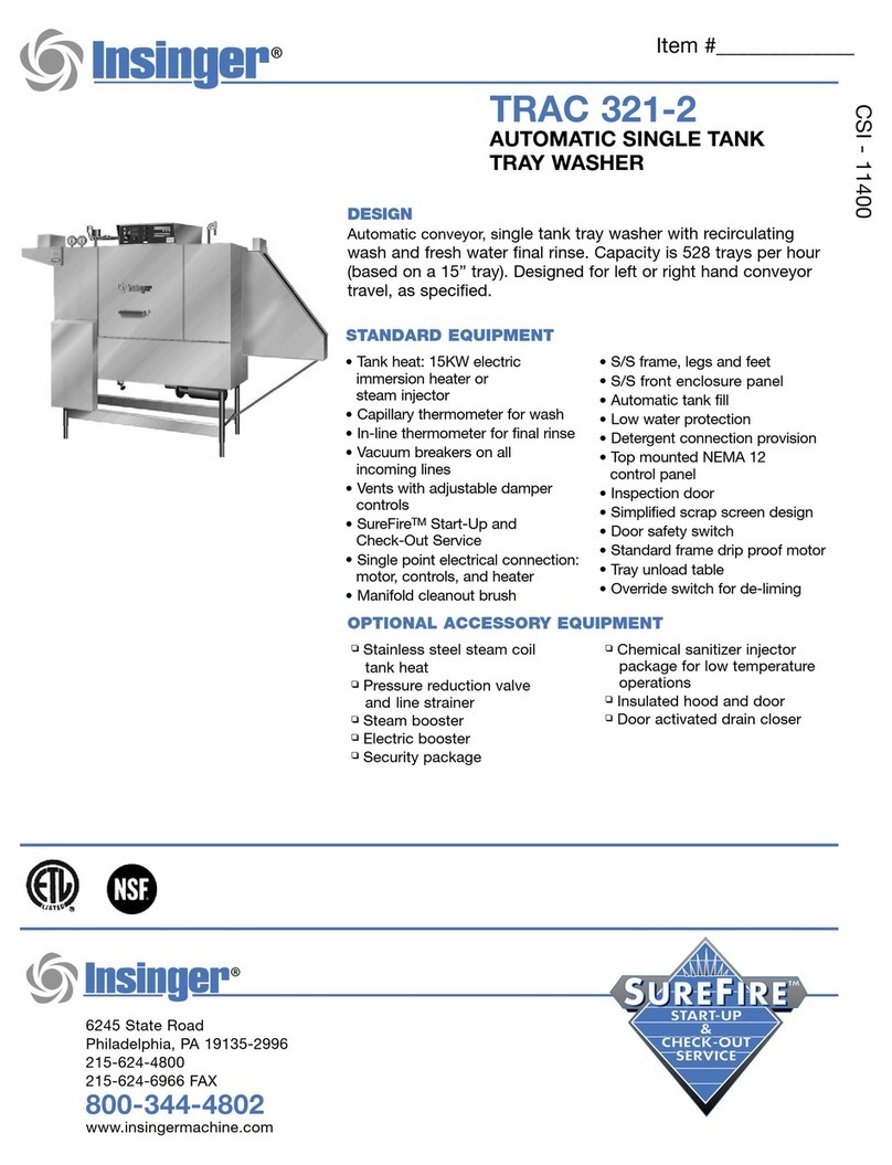
Technical Drawings
8ACK
SPLASH
86"
8~;::~
:s;._
L...LJE
t L
I{_
OPENING
t
'(_
/l DIS
HWA
SHER
RIM
ROLL
TYPICAL
TABLE CONNECTION
tfi
1
10
~
53
3/4
==1
(Hl)I
~
T:~1
~
I I
.I
~""
-1
]
I
""--.J
"S~f':
--.~~
,,.,
C,
i
I
"'-.,..
iu.,-,
:s
'
[L
~
~
!£>
----~
SEE
NOTt
#1
@
11
3/8(H1)r-~
7
1/4
~J.
10~~~
S
ff
NOTE
~I~•
7
1/
8
@
~
:S
I
1/4
i
~
4
I t SEE
NOTc
#3
h
(5
cJ
l:
_,
_,
SC
~
IN
S
TALLATION
AND
LAYOUT
DETAIL
4 • MIN.
21
ij
'
~
~
,__,,
_
h
2s
"l
cJ'
"'
"'
;;';
""
l
oS
Cl
('~
~
--E-
::;
-t
t_j_
""
=r====~~~~I
w~
I+
~"'
f a1
1t
:+1
t!
:'!
; l
J~
~
-&
~
INSTALLA
T!ON
CONNECTIONS
LmI
DESCR
IPT
ION
HI
I
HOT
WA
TEH
TO
AUTO
FILL
-
140'
F
H2 I
HOT
WA
/Di'
TO
FINAL
RINSE
-
180'
F
H3
HOT
WATER
TO
STEAM
BOOSTER
H4
HOT
WATER
TO
ELECTRIC
BOOSTER
51
JST
EA
M
TO
TANKS
-
WASH
52
JSTEAM
TO
TANKS
-
RINSE
53
I
STEAM
TO
BOOSTER
D1J
DHAIN
CONNECTION
-
WASH
&
RINSE
D2
I
Dl?AIN
CONNECTION
-
Pl?EWASH
RI I
CONDENSATE
RETURN
-
TANK
COILS
F?2
CONDENS
ATE
RETURN
-
BOOSTER
El
ELECT.
SERI/CE
-
WASHER
MT.RS.
£2
ELEC
T.
SERI/CE
-
WASH
HT
RS.
£3
ELECT.
SERI/CE
-
RINSE
HTRS.
E4
ELECT.
SERI/CE
-
BOOSTER
VJ
I
vEN~
EXHAUST
(4 x 12)
SIZE
J/4
FNPT
1/2
FNPT
1
/2
FNPT
1/2
FNPT
1/2
FNPT
J/ 4
FNPT
11/2
or
/"
FNPT
2"
FNPT
1 I 2 m0T
I 2
FNPT
I 2
FNPT
26
HP
8
KW
15
KW
24/45
KW
15
0
CFM
EACH
~
I I I
~
1'
" m
~
"'
0)
I s
55
3/
4---
I =
--
--
-~i----
5
%83{
;4
~I
~
86
"Jf--l--~
f-1
3
1
5-++~~+IS
NOTES: ILEFT
TO
,9/GH
T
FEED_
I
/. END c
o~s
tlATH
VENT & ADJUSTABLE DAMPERS
FURNISHED 01/LY
Wf-/
EN
SPECIFIED.
2. " • FOR
HO
T
WATER
TO
BOOS
TE
R
140"
F S
TD
/ 110" F SPECIAL.
3. ALLOW
24'"
MIN.
CLEARANCE BELOW DISHTABLE
TD
SERVICE
ELECTRICAL EQUIPM
ENT
2 3
/4
--j
~26
7/
8 -
l
nformal
ian
and
Sp
ec
ifica
tio
ns
Subject
to
Chonqe Without
Notice
.
ZEfrf?:Jffif/:i
SPEEDE,9
86-3
w
ith
SWI
NG DOORS
MAY
fl/OT
lK
!li'SCI.IRD
m A
HY
DOUBLE
TANK
CO
NVEYOR
TYPE
O(
SH
WASHlNG
MAC
f-ffN
E
l'Hfl'Nl,_1"=»~~~1"'r
~
• Ph~adel
1>
hia, PA
19135
-~':,'g.
%.~o;,
"''
()[)1':
Ins
in
g
er
c2,
5J
B2•-•
soo
~•VUAC1l/RWc;
~
A
S1,W1L,tR
OI?
{
})
FAX 215
624
-
6966
5;A~~~7~
DRW~
J:
JJB
03.
29.
11
D'WG
.
NO.
REV
llfA°;/{p'ftf':"~fiiuSW::C'
REV:
-PEEDER
B6
S"'1rJG
L
A~TE"
U:GJL
AC:,)Oi'J.
FILE:
-
Technical Drawings
BACK
SPLASH
86
. B
;;
;::
;
~
.
L_],J£_ 1
r t OP£N
IN
G
t
'(_
t_
D
IS
H
WAS
HER
RIM
ROL
L
TYPICAL TABLE CONNECTION
f
~j
~
-~~
fi
~~
~
~
53 3
/4
~
'-
st--,
"•
-:i::
'---
r---<h
)
~
J
~
~,
I M r 1
~
I.,
I
NS
TALLA
TIO
N
AN
D
LA
YO
UT
DETA
IL
I I 3
/B
(
HI
)
---j---
1
~~~
7 I
/4
--t-,
~
@
~
..,
t T
SEE NOTE #1
T--i===----
85
1/2
@
28
7/8(H~
~
0
~
•
S
EE
NOTE
#3
-
~
I
:/4
:S
~
@
7
7/8~
'
ffE
NO
TE
#1
4
~
~
4"
M
Iii
.
<
~~
~~
h
,
"
<-
'
~~
j
o'
'
"1'"~
+-
---""'Ll,1--l--~
""
7 '1
~
C
' ~ '
J f j...
i..
21 1
7/
8
20
7/
4 / I
i _,
~
~
~
a
f
~
~
G;
"'1
~~
;
!-I
-t
~
:;i
,W
,
-f-
~1
·{
+1
"
!1===1~=1;:=J
~
j ;
~
!t4: t
i_
11J--l
=~p===~~,=---=
~
~
~
---
@=1
D 6~
~J
------i~-
55
3/4
51 I
~
INSTALLATION CONNECTIONS
i------,--
---f&21)(£,#--+i'
~ d ;;,-
L
TR
DESCRIPTION
SI
ZE
~
,,-,-.-
~-
---i..~-
"'
HI
HOT
WATER
TO
IUTO
FILL
-140' F 314
FNPT
41----
--'----
54
5/1
6
/3
H2 HOT
WATER
TO
FINAL
R
IN
SE
-
180
"F 112
FNPT
I
-----'-----
86
H3
HOT
WATER
TO
STEAM
BOOSTER
1/2
FNPT
______
__,;
;;.;;....
____
_
H4
HOT
WAIIR
TO
EL
ECm!
C
BOOST[R
112
FNPT
I R!GHT
TO
LEFT
FEED I
Si
STEAM
TO
TAN!SS
-WA
SH
1/2
FNPT
"
52
I
STEAM
TO
TANKS
-
/?INS[
I
)ll.l!
I
PT
SJ I
STEAM
TO
BOOS/El?
1
1/2
or
1'
FNP
T
D1
I
DRAIN
CONNECT
I
ON
-
WAS
H &
RINSE
I
2"
FNPT
D2
JDRA
IN
CONNECTION
-
PREWASH
I 1
1/2
F
NP
T
RI J
CONDENSATr
RE/URN
-TA
NK
CO
I
LS
J
1/2
FNPT
R2
ICONDE
N
SAT[
RU/Jl?N
-
BOO
S
TER
I 1)2
FNPT
£1
!ELECT.
SERVICE
-
WASHER
MTRS.
I 2.6
HP
E2
I
ELECT.
SERVICE
-
WASH
HTRS.
I 8
KW
£3
!ELECT.
5£/?VICE
-
/?INS£
HTRS
. [
/5
KW
£4 !
ELECT.
SERv/CE
-
BOOSTER
24/45
KW
VI
I
VEN~
EXHAUST
(4
x
12)
I 350
CFM
EAC
H
//OTES:
I.
END
COM_S
WI
TH
VENT &
ADJ
USTABLE D
AMP
ERS
FURN
IS
HED ONLY
WHEN
SPECIFIED.
2. " " FDR HOT
WATER
TO
BOOSTER 1
40
" F STD /
110
" F SPECIAL.
3.
ALLOW
24"
MIN. CLEARANCE BELOW DISHTABLE
TO
SERVICE
ELE~TRICAL EQUIPMEN
T.
2 3
/4
--1
l--2
6 7
/8
-
Informat
ion
an
d
Specifi
cat
i
ons
Subject
to
Chanqe
Wit
hout
N
ot
ice.
'Jf::=~~w""'.:
SPEEDER
86
- 3 w
it
h
SWING
DOOR
S
J!r'fi:~i£':ff::!//J1:J.Y
O
OUB
lE
T
ANI<
Cotl'vF.YDR
T~E
DIS~WASHING MACH
IN
E
f'UlrfYJSCl'«11A71M..t11JrNOr
~
I •
Ph
1l
ade
lp
h1<l,
P A 191
35
t.Ml
~w~/~"~~"115
(w~
nsInger
c2
1s
)
624
- 4
80
0
11/NttFA.ClUll!HC
(TA
~R
OR
~1)
F
AX
2 1 5
62
4 -
6966
~~:rs~T.i.i
□
R
'W
N
:
JJB 03.29.
11
□
WG
.
rJ
O.
RE
V
M'l'W°P~~~
r
RE
V: -
PEEOER
86
SW
I
UC
R
.ll
'l"
fNJPRJitll: = A
C110\t
F IL
E:
-
CSI - 11400
Approval
Date
Project
Item
Quantity
Super 106
Three Tank Conveyor Dishwasher
6245 State Road ∙ Philadelphia, PA 19135 ∙ PH: 800-344-4802 ∙ FX: 215-624-6966 ∙ www.in sing erma ch ine. com
Automatic conveyor, rack type, three tank dishwasher
with recirculating pre-wash, wash, rinse and fresh
water final rinse.
0.72 gallons/rack final rinse consumption
Capacity is 330 (20” x 20”) racks per hour or 8,250
dishes per hour
Error proof replacement with color-coded curtains
CrossFire Wash System power
sprays water horizontally, as
well as, from above and below,
cleaning and sanitizing the
dirtiest of ware.
STANDARD FEATURES
CrossFire Wash System
Color-coded curtains
Tank heat:
Electric immersion heater
Steam injector
Capillary thermometers for wash and rinse
In-line thermometer for final rinse
Vacuum breaker on all incoming water lines
Manifold clean-out brush
SureFire Start-Up & Check-Out Service
Inspection door
Ventilation fan connection provision
S/S frame, legs and feet
S/S front enclosure panel
Automatic tank fill
Low water protection
Detergent connection provision
Elevated top mounted NEMA 12 control panel
Easily-cleaned crowned hood top
Simplified scrap screen design
Door safety switch
Standard frame drip proof motors
Energy saver
Override switch for deliming
End caps/pipe plugs secured to prevent loss
Timing belt conveyor drive
OPTIONS
Stainless steel steam coil tank heat
Steam booster
Electric booster
Single point electrical connection: motors, controls and
tank heat. (Booster requires a separate connection)
End cowls with vent and adjustable damper controls
S/S splash guards
Security package
Totally enclosed motors
Rack limit switch
Power Loader
Power Unloader
Door activated drain closers
Insulated hood and door
Plastic 20” x 20” racks (plate or silver)
SPECIFIER STATEMENT
Specified unit will be an Insinger Super 106-2 double tank rack conveyor
dishwasher with pre-wash. Features include CrossFire Wash System,
capillary thermometer for wash and rinse, in-line thermometer for final
rinse, vacuum breaker, SureFire Start-Up & Check-Out service, inspection
door automatic tank fill, low water protection, door safety switch, energy
saver, timing belt conveyor drive, and 304 stainless steel construction.
~Jlnsinger
6245 State Road ∙ Philadelphia, PA 19135 ∙ PH: 800-344-4802 ∙ FX: 215-624-6966 ∙ www.in sing erma ch ine. com
Additional Information
SPECIFICATIONS
CONSTRUCTION- Hood and tank constructed of 16 gauge type 304
S/S. Hood unit of all welded seamless construction. S/S frame, legs
and feet. All internal castings are non-corrosive lead free nickel alloy,
bronze or S/S.
DOORS- Extra large die formed 18-8 type 304 S/S front inspection
door riding in all S/S channels. A triple ply leading edge on the door
channels made of S/S with no plastic or nylon sleeves or liners used.
Two intermediate S/S door safety stops on door.
CONVEYORS- One S/S roller chain conveyor, with rack driving
lugs every sixth link, running along the front of the machine. Eleven
free spinning rollers placed along the back wall of the machine.
Conveyor accommodates all standard 20” racks. Conveyor drive
system includes direct drive gear motor with frictionless, trouble-free
clutch system, spring-loaded and automatically re-engaging. Racks
conveyed automatically through washing and rinsing systems,
powered by an independent 1/15 hp drive motor.
PUMP- Centrifugal type “packless” pump with a brass petcock
drains. Construction includes ceramic seal and a balanced cast
impeller on a precision ground stainless steel shaft, extension or
sleeve. All working parts mounted as an assembly and removable
as a unit without disturbing pump housing. 1 hp motor for each
wash and rinse pump: standard horizontal C-face frame, drip proof,
internally cooled with ball-bearing construction.
CONTROLS- Top mounted NEMA 12 control enclosure, with 3.5
inch air gap between hood and enclosure, housing motor overload
protection, contactors, transformers and all other dishwasher
controls. All controls safe low voltage 24 VAC.
ENERGY SAVER- Rack actuated lever automatically operates the
final rinse solenoid only when a rack passes, saving water and
energy. The lever also activates an adjustable timer control. If no
ware passes during the set time, the machine shuts down.
SPRAY SYSTEM- Spray arms made of type 304 stainless steel pipe.
Spray assemblies removable without the use of tools.
WASH- Upper and lower manifolds with the patented CrossFire®
Wash System. One manifold above with 3 power wash arms, each
with 9 high pressure cleaning slots and one manifold below with 3
power wash arms, each with 9 high pressure cleaning slots. The
slots are precision milled for water control producing a fan spray.
Wash arms are fillet welded to the S/S manifold. The CrossFire®
Wash System provides 4 horizontally spraying high pressure nozzles.
RINSE- Upper and lower manifolds. One manifold above with 3
power rinse arms, each with 9 high pressure rinsing slots and one
manifold below with 3 power rinse arms, each with 9 high pressure
rinsing slots. The slots are precision milled for water control
producing a fan spray. Rinse arms are fillet welded to the S/S
manifold.
FINAL RINSE- Six nozzles above and three nozzles below threaded
into S/S schedule 40 pipes. Nozzle assemblies produce a fan spray
reducing water consumption, maximizing heat retention.
DRAIN- Drain valve externally controlled. Overflow assembly with
skimmer cap is removable without the use of tools for drain line
inspection. Heater is protected by low water level control.
Note: Exhaust requirements are for pant leg connections only. For
hood type, CFM requirements vary, consult hood manufacturer for
specific sizing.
Note: Due to product improvement we reserve the right to
change information and specifications without notice.
Capacity Per Hour 330 racks
8250 dishes
300-600 meals
Tank Capacity 14 gals. (pre-wash)
25 gals. (wash)
25 gals. (rinse)
Motor Size 1/2 hp (pre-wash)
1 1/2 hp (wash)
1 1/2 hp (rinse)
1/6 hp (conveyor)
Electric Usage 7.5 kW wash tank
22.5 kW rinse tank
27 kW booster 40° rise
45 kW booster 70° rise
Steam Consumption
at 20 psi min.
108 lbs./hour tank
84 lbs./hour booster 40° rise
147 lbs./hour booster 70° rise
Final Rinse Peak Flow
at 20 psi min.
3.98 gallons/minute
Final Rinse Consumption
at 20 psi min.
239 gallons/hour
0.72 gallons/rack
Exhaust Hood
Requirement
350 CFM Load
350 CFM unload
Peak Rate Drain Flow 23 gallons/minute
Shipping Weight 1400 lbs.
Machine Electrical
Motors, Controls, Tank Heat Steam Electric
240/1/60
208/3/60
240/3/60
480/3/60
380/3/50
28.6
18.5
16.8
8.4
10.1
N/A
101.8
88.9
44.5
55.7
Technical Drawings
~
~
INSTALLATION
AND
LAYOUT
DETAIL
63
J/4
OVERALJ.
LENGTH
(Sff
CHART)
1-+-
-
-'I]~--=--=
~
29
---I-@-
~
SEE
NOTE
'1 =
ii
53
------@-j
5 i-@
I
_J
. J
J:....i.JE
~.lt
_=l
~
1
~-~~
",t,
!
...
~-
-
~-
'1-t-r -
l<)ll
"
01
l
■
l+-l-~~1-
-1
BETYEEN
106·
Ldd:i
RIM
ROLL
TABLES
DPfCAL
TABlE
CONNECTION
-1~
7
i--t@
F
28
-----;
~
1 'o
~
105
r/2
I
!~:~=
i
\U4[f
@-is
H
~B~
1!
ir,
c_,,
,ft
~l
,1
- - I
.
~
~
Q::
~
...
~
~
:::I
i
~
0
~
u "
!"
Q,b
'"'"I
H +
__
=i_l
~
-=J~
io
4
M/N.-1
I-
Il
~
J
.,
~
~
ISTER
.L..,
-t -t
1•1-++
-1~1-+LC
"'
~
.
u1,,
I~
....
-
~
46
.~
67
l----@:-----5456
~
63
LEFT
TO
RIGHT
FEED
Nfll£S;._
65--
69-
1.
END
COHlS
'MTH
VENT
FURNISHED
ONLY
WHEN
SPECIFIED.
2.
•
t,,"
FOR
HOT
Wit
ID?
TO
BOOSm?
140'
F
STD
/
110'
F
SPECIAL.
4
J/8
Information
and
Specifications
Subiect
to
Change Without Notice.
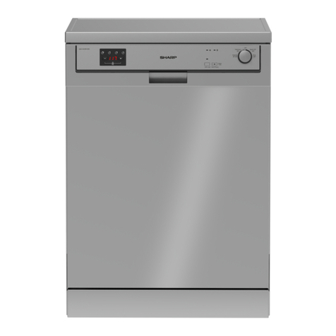
SUPER
106-2
1ffiPLC TA/Ill(
COV1CJ'tw
~
0/SHWASHIIW
MACHlltc
I •
Philadelphia.
PA
191~
ns
In
g
er
c21si
624-4800
FAX
(215) 624-691M1
DIW:.
NO.
12.10.92
SCALE
'
REV:
K8M
07.29.08 1/2" -
''
I
S106-
2L
-•-
~\~UM-2L
REV
J
Technical Drawings
OVERALL
L£NGTH
BACK
SPLASH
(SEE
~ART}
t-------6:J
:J/4----
r
,
~
1 !L
+1,
~
~
I
!~----~~~I•
~tt
•
...
=..~~: rfrr
r+
~
1 b
J:...JJE
-E-
+-
------ft'-
--+-m
INSTALLATION
AND
LAYOUT
DETAIL
1\
~
I I I
........
It
I",
I -~(
:;i
~
.-
~
;:i:
~
;!:
®iB
-E-
-i,or
Ft--28
7
;f--<E}--42------:!:I;;:
SEE
NOTE
#1
~14
,,
,-,
,.
r1~1.ty
:
c:±....
I
::J
~
ELECTRICAL
I, ' , I
FQUIPMFNT
!
ls
~-.I
0
~
T
:•
~j_
__
-+-
..._
, r
rl
~
....
r i
-1=.L
...
=i=I=~
lttt
I I
-.~"'~~·
-------65-------(Rt)--.,
7
~
~I
I
♦
d~
.
~
&'ill:
....
-
~
It)
<o
~
- I I
It
~
~
4
:J/8
---
46
~
----54~
INSTALLAnoN CONNECnONs I
6;2~
i----------lf-106
---------
"'
~
~
•:Jt~L,_
LTR
DESCRIPnON
SIZE
t-•
----69~
HI
HOT
WA1Ei'i'
TO
AUTO
FILL
-140' F J
'4
FIPS
H2
HOT
WAlFR
TO
FINAL
RINSE
-
180"
F 1
'2
FIPS
RIGHT
TO
LEFT
FEED
HJ
JHOT
WA1Ei'i'
TO
STEAM
BOOSTER.,
j
1/2
FIPS
H4
IHOT
WAlFR
TO
ELEC.
BOOSTFR...
I
¾4
RPS
rASH
1
'2
FIPS
INS£
I
3/4
RPS
1"
FIP~
RPS
FIPS
FIPS
1
4
HP
l<W
'2
KW
l<W
l:JillIS,;.
1.
END
co~s
WITH
VENT
FURNISHED
ONLY lftffEN
~CIFIED.
2.
"t:,."
FOR
HOT
WA7ER
ro
BOOSTER
140" F
sm
/ 110· F
SPECIAL.
OVERALL
DIMENSIONS
TYPE
I
LENGTH
S
AM
-R
132
ELECT.
W.
R
FINAL
RINSE
105
I '2
ELECTRIC
OOSTER
13!
STEAM
-
WITHOUT
BOOSTER
J
114
1/4
Information
and
Specifications
Subject to Chanqe Without Notice.
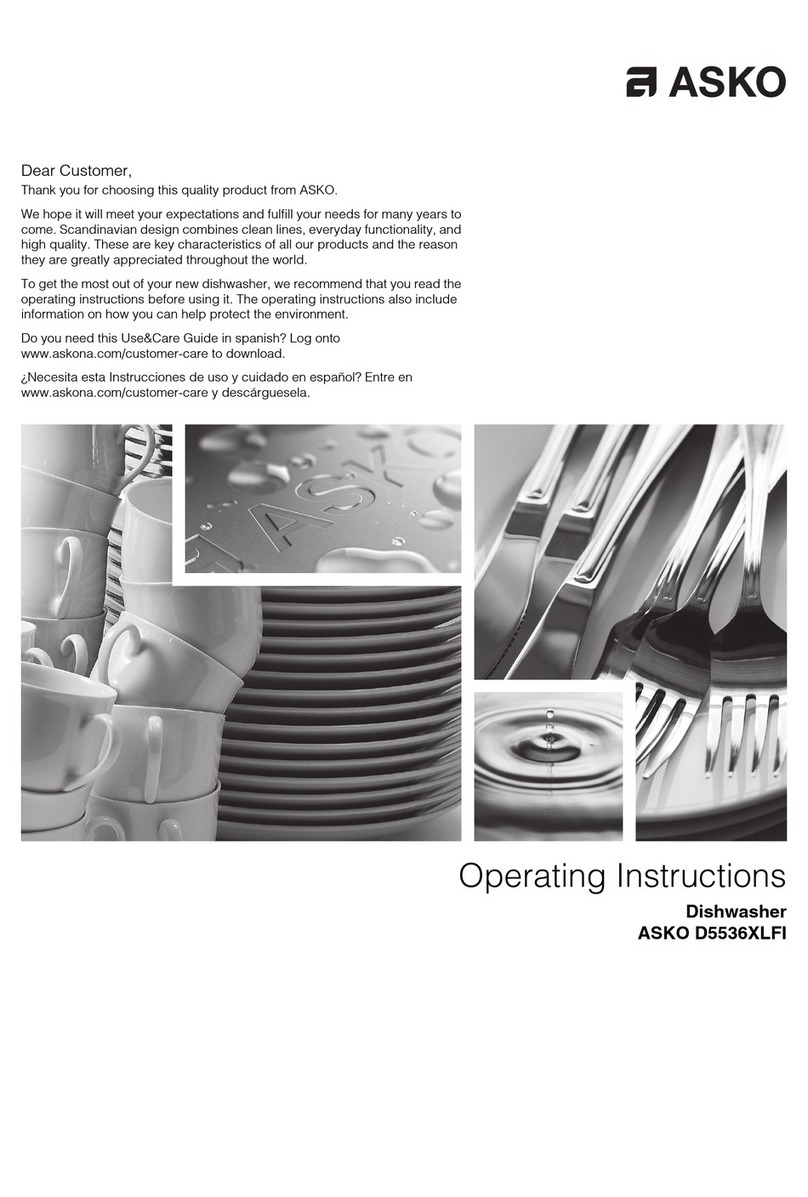
SUPER-106-2
lRIPt£
TANK
OOIYIO!:R
7lf'F
DISH'IIASHINf:
SYS1EN
I • Phladalphl
ai,
PA
19135
nS
In
ger
FA~21
~
562:a~ss
UKWN:
t.1111 t2-1Q.92
SCALE
DWG.
NO.
REV
REV: -KBU -07.29.08 1
12· = ,·
S106-2R
J
Speeder Super Tech Manual 6_2015 www.insingermachine.com 800-344-4802
PART 1 TECHNICAL INFORMATION
INSINGER MACHINE COMPANY LIMITED WARRANTY
or failure to perform normal and routine
maintenance as set out in the instruction booklet
(operating instructions) or for improper operation
or failure to follow normal operating instructions
(as set out in the instruction booklet). Insinger
is not responsible nor liable for any conditions
of erosion or corrosion caused by corrosive
detergents, acids, lye or other chemicals used in
the washing and or cleaning process.
Service must be done by either Insinger Appointed
Service Agencies or agencies receiving prior
authorization from Insinger.
All warranty work must be done during normal
working hours, unless purchaser receives prior
authorization from Insinger.
There are no other express warrants except
as set forth herein and any applicable implied
warranties of merchantability and tness are
limited in duration to the period of coverage of
this express written limited warranty. This limited
warranty supersedes all other express warranties,
implied warranties of merchant-ability and tness
or limited warranties as of this date, January 1,
1998. Some states do not allow limitation on how
long an implied warranty lasts so this limitation
may not apply to you.
Insinger is not liable for any special, indirect or
consequential damages. Some states do not
allow the exclusion or limitation of incidental or
consequential damages, so this limitation nor
exclusion may not apply to you.
Insinger does not authorize any person or
company to assume for it any other obligation or
liability in connection with the sale, installation,
use, removal, return or replacement of its
equipment: and no such representations are
binding on Insinger.
Insinger Machine Company, Inc. (Insinger) hereby
warrants to the original retail purchaser of this
Insinger Machine Company, Inc. product, that if
it is assembled and operated in accordance with
the printed instructions accompanying it, then
for a period of either 15 months from the date
of shipment from Insinger or 1 year (12 months)
from the date of installation or start-up that said
Insinger product shall be free from defects in
material and workmanship. Whichever one of
the two aforestated limited warranty time periods
is the shortest shall be the applicable limited
warranty coverage time period.
Insinger may require reasonable proof of your
date of purchase; therefore, you should retain
your copy of invoice or shipping document.
This limited warranty shall be limited to the repair or
replacement of parts which prove defective under
normal use and service and which on examination
shall indicate, to Insinger’s satisfaction, they
are defective. Any part that is claimed to be
defective and covered by this limited warranty
must be returned to Insinger. An RMA# must be
obtained from the Insinger Warranty Department
before returning any material. Return may be
done through an Authorized Service Agency.
Furnish serial number of machine and RMA # with
shipment and send to:
Insinger Machine Company
6245 State Road
Philadelphia, PA 19135-2996
If Insinger’s inspection conrms the defect and
the claim, Insinger will repair or replace such
part without charge and return it to you freight or
postage prepaid.
This limited warranty does not cover any
failure or accident, abuse, misuse, alteration,
misapplication, improper installation, re, ood,
acts of God or improper maintenance or service,
~Jlnsinger
PART
2
INSTALIATION
and
OPERATION
INSTRUCTIONS
RACK CONVEYOR DISHMACHINES
INSTALLATION INSTRUCTIONS
Part
2~
SectionA
A.
l PLACEMENT
A.1.1
Carefully
uncrate
machine.
Take
caution
to
not
damage
components
which
may
be
mounted
on
the
top
or
sides
of
the
machine.
A.1.2
Set
unit
in
place
and
adjust
the
feet
to
level
the
machine.
A.1.3
Fasten
the
tables
to
the
load
and
unload
side
of
the
machine.
Most
installations
require
fastening
the
turn
-down
lip
of
the
dish
tables
to
the
side
of
the
machine
with
flathead
counter
-sunk
screws.
The
table
design
should
provide
horizontal
clearance
of
30"
for
servicing.
A.2
ELECTRICAL
CONNECTIONS
A.2.1
Connect
electrical
lines
sized
for
the
correct
voltage,
current
and
phase
of
the
machine.
These
should
agree
with
machine
requirements
indicated
on
the
nameplate
and
labels
in
control
panel.
A.2.2
On
machines
not
pro~ided
with
a
single-point
connection
there
is
an
electrical
connection
required
for
the,
1.
Pumps
and
control
circuit,
2.
Wash
tank
heater(s)
and,
3.
Rinse
tank
heaters
(if
provided).
A.2.3
If
an
electric
booster
is
provided,
connect
power
directly
to
the
booster.
NO~E
In
each
case
connections
must
be
made
to
a
circuit
breaker
or
fused
disconnect
as
provided
by
the
end-user
and
required
by
local
codes.
A
wiring
diagram
is
laminated
inside
the
control
panel.
IMPORTANT
As
with
any
3
phase
system,
an
electrician
should
check
all
motors
for
proper
phasing,
.
i.e.
,
Pump
motors
must
be
running
in
direction
indicated
by
arrow
on
housing.
A.3
MECHANICAL
CONNECTIONS
A.3.1
Connect
140°
water
lines
for
tank
fills
and
booster
as
tagged
and
noted
on
the
installation
drawings.
A.3.2
If
machine
is
provided
with
steam
heat
connect
the
steam
lines
and
steam
condensate
lines
as
tagged
and
noted
on
installation
drawings.
If
machine
is
provided
with
gas
heat,
connect
the
gas
lines
for
each
tank.
cm
q:\wpSl\manual\rack.mnl
rlsd:
4/91,
rvsd:
3/93,
4/94
RACK CONVEYOR DISHMACHINES
INSTALLATION INSTRUCTIONS
Part
2,
Section
A
A.3
MECHANIC.AL
CONNECTIONS,
cont'd
A.3.3
Connect
the
drain
lines.
A.3.4
If
an
electric
booster
is
provided
a
140°
water
A.4
HVAC
A.4.
1
A.4
.2
connection
is
necessary.
If
a
steam
booster
a
140°
water
connection
is
necessary
as
well
as
a
condensate
line.
NOTE
Drain
lines
must
be
as
specified
on
installation
drawings.
Drain
line
must
be
properly
vented
and
have
fall
of
not
less
than~"
to
the
foot
of
proper
flow.
Local
plumbing
codes
may
require
drains
to
flow
into
an
open
gap
with
an
opening
twice
the
diameter
of
the
pipe.
Check
with
your
local
plumbing
codes
for
the
type
of
drain
·
connection
required.
NOTE
All
lines
must
be
flushed
prior
to
use
to
remove
debris.
IMPORTANT
Do
not
reduce
the
size
of
lines
as
specified
in
installation
drawings.
All
lines
are
sized
to
facilitate
necessary
flows,
pressures,
etc.
Ventilation
system
should
be
sized
to
provide
adequate
ventilation
per
machine
specs.
Refer
to
spec
sheet.
Stainless
steel,
watertight
ducting
should
be
connected
to
the
vent
cowls
(optional}
on
each
end
of
the
machine.
A.5
Chemicals
A.5.1
Upon
completed
installation
of
the
dishwasher
contact
a
local
detergent/chemical
supplier
for
the
correct
chemicals
for
your
area.
A.5.2
Electrical
connection
points
for
the
detergent
dispenser
and
rinse
injector
are
located
inside
the
control
panel.
Refer
to
the
wiring
diagram
for
this
machine
for
the
proper
connection
points.
Dispensers
may
be
connected
on
either
the
primary
voltage
side
of
the
machine
or
the
24VAC
control
voltage
side.
cm
q:\wpSl\manual\rack.mnl
rlsd:
4/91,
rvsd:
3/93,
4/94
RACK CONVEYOR DISHMACHINES
INSTALLATION INSTRUCTIONS
Part
2,
Section
A
A.5
Chemicals,
cont'd
CAUTION
When
connecting
on
the
24VAC
control
voltage
side
0£
the
transformer,
total
load
must
not
exceed
SOVA.
A.5.3
The
detergent
density
probe
should
be
located
in
a
convenient
place
in
the
wash
tank.
A.6
Tabling
A.6.1
Load
and
unload
tables
should
be
pitched
towards
the
machine
to
return
excess
water
into
the
machine.
NO'I'E
Machines
with
short
unload
tables
should
utilize
a
rack
limit
switch
to
shut
the
machine
down
if
clean
racks
pile-up.
This
will
extend
the
life
of
the
drive
system.
A.7
Initial
Start-up
Adjustments
A.7.1
Tank
Overfill
Adjustment
A.7.1.1
Locate
tank
overfill
timer
in
the
control
panel.
See
the
control
panel
layout
drawing
located
in
Section
3,
Electrical
Schematic
and
Replacement
Parts.
A.7.1.2
The
overfill
timer
starts
timing
when
the
upper
level
float
is
actuated.
Adjust
the
overfill
timer
pot.
to
turn
the
tank
fill
solenoid
off
when
the
water
level
is
1/2"
below
the
lip
of
the
overflow
tube.
A.7.2
Conveyor
Jam
Adjustment
A.7.2.1
Remove
the
mechanism
guard
to
gain
access
to
the
conveyor
drive.
A.7.2.2.
Locate
the
compression
spring
(refer
to
Dwg.
#1397-1,
Drive
Mechanism
Assembly).
Factory
set
compression
dimension
is
a
nominal
3
13/16".
Installations
washing
heavier
ware
may
need
to
adjust
this
for
more
compression
to
keep
the
machine
from
shutting
down
prematurely.
A.7.2.3
Should
the
drive
mechanism
switch
be
activated
by
a
conveyor
jam,
the
"Check
Conveyor"
light
on
the
control
panel
will
illuminate
and
the
machine
will
shut
down.
A.7.2.4
To
restart
the
machine,
clear
the
jam
and
press
the
green
"Start"
button.
A.8.2
Final
Rinse
Pressure
Adjustment
A.8.2.1
The
final
rinse
pressure
must
be
adjusted
to
20PSI.
This
is
done
by
adjusting
the
pressure
regulator.
cm
q:\wpSl\manual\rack.mnl
rlsd:
4/91,
rvsd:
3/93,
4/94

This manual suits for next models

2

Other Insinger Dishwasher manuals

Insinger DEFENDER 17 User manual

Insinger

Insinger DEFENDER 17 User manual

Insinger TRAC 321-2 SERIES User manual

Insinger

Insinger TRAC 321-2 SERIES User manual

Insinger CENTURY 14 User manual

Insinger

Insinger CENTURY 14 User manual

Insinger COMMANDER 18-5 User manual

Insinger

Insinger COMMANDER 18-5 User manual

Insinger COMMANDER 18-5H User manual

Insinger

Insinger COMMANDER 18-5H User manual

Insinger speeder series User manual

Insinger

Insinger speeder series User manual

Insinger RL-30 User manual

Insinger

Insinger RL-30 User manual

Insinger COMMANDER 18-5 User manual

Insinger

Insinger COMMANDER 18-5 User manual

Insinger SUPER 106-2 User manual

Insinger

Insinger SUPER 106-2 User manual

Insinger CLIPPER RC User manual

Insinger

Insinger CLIPPER RC User manual

Insinger GalleyMaster 135-LH-E User manual

Insinger

Insinger GalleyMaster 135-LH-E User manual

Insinger ADMIRAL 44-4 User manual

Insinger

Insinger ADMIRAL 44-4 User manual

Insinger RL-30 User manual

Insinger

Insinger RL-30 User manual

Insinger USN-72 User manual

Insinger

Insinger USN-72 User manual

Insinger LIEUTENANT SERIES Manual

Insinger

Insinger LIEUTENANT SERIES Manual

Insinger TRAC 321-2 RPW User manual

Insinger

Insinger TRAC 321-2 RPW User manual

Insinger 45SA User manual

Insinger

Insinger 45SA User manual

Insinger RL-30 User manual

Insinger

Insinger RL-30 User manual

Insinger CS-5H User manual

Insinger

Insinger CS-5H User manual

Insinger ADMIRAL 44 ADVANCED User manual

Insinger

Insinger ADMIRAL 44 ADVANCED User manual

Insinger ENSIGN 40-2 User manual

Insinger

Insinger ENSIGN 40-2 User manual

Insinger GalleyMaster 135-LH-E User manual

Insinger

Insinger GalleyMaster 135-LH-E User manual

Insinger Commander 18-6 User manual

Insinger

Insinger Commander 18-6 User manual

Insinger ADMIRAL 44-4 User manual

Insinger

Insinger ADMIRAL 44-4 User manual

Popular Dishwasher manuals by other brands

Concept2 MNV5860 manual

Concept2

Concept2 MNV5860 manual

Asko DFI756MUXXL user manual

Asko

Asko DFI756MUXXL user manual

TEKNIX TFD615W instruction manual

TEKNIX

TEKNIX TFD615W instruction manual

Sharp QW-HD44UD-DE user manual

Sharp

Sharp QW-HD44UD-DE user manual

Gorenje GI55110 operating instructions

Gorenje

Gorenje GI55110 operating instructions

Miele PG 8083 SCVi operating instructions

Miele

Miele PG 8083 SCVi operating instructions

Baumatic BDID 615 instruction manual

Baumatic

Baumatic BDID 615 instruction manual

BENDIX BDW46 Instruction book

BENDIX

BENDIX BDW46 Instruction book

Fisher & Paykel DishDrawer DD602I installation instructions

Fisher & Paykel

Fisher & Paykel DishDrawer DD602I installation instructions

LG DFC425 Series owner's manual

LG

LG DFC425 Series owner's manual

GE GDF510-540 Series owner's manual

GE

GE GDF510-540 Series owner's manual

Zanussi DA 4131 Instruction book

Zanussi

Zanussi DA 4131 Instruction book

Solt GGSDW6012S user manual

Solt

Solt GGSDW6012S user manual

Hotpoint LSB 5B019 Instructions for use

Hotpoint

Hotpoint LSB 5B019 Instructions for use

Frigidaire Frididaire Use & care manual

Frigidaire

Frigidaire Frididaire Use & care manual

American Dish Service ASQ Service manual

American Dish Service

American Dish Service ASQ Service manual

Jenn-Air JDB8000AWS installation instructions

Jenn-Air

Jenn-Air JDB8000AWS installation instructions

Bosch SHPM65W52N operating instructions

Bosch

Bosch SHPM65W52N operating instructions

manuals.online logo
manuals.online logoBrands
  • About & Mission
  • Contact us
  • Privacy Policy
  • Terms and Conditions

Copyright 2025 Manuals.Online. All Rights Reserved.