Electrolux Professional 534411 User manual

Dryer tunnel
22″ - Corner 90°
EN Installation manual *
*Original instructions 59566QP02- 2023.11

2
Installation diagram DT 22″
560
46
348
D
1127
400
30
583109
500
659
1785
874
50795

3
Installation diagram Corner 90°
664
664
872
872
877
456
534
664
872
6565
595
456
872
65
664

4
Drilling diagrams
Electrolux rack handling system
90° Bend Right (counterclockwise)
PNC: 863237
80
115.5
23.5
5
191
150

5
Drilling diagrams
Electrolux rack handling system
90° Bend Left (clockwise)
150
191
80
23.5
5
115.5
PNC: 863237

6
Drilling diagrams
Electrolux rack handling system
180° Bend Right (counterclockwise)
PNC: 863238
80
23.5
5
191
150
9.5

7
Drilling diagrams
Electrolux rack handling system
180° Bend Left (clockwise)
80191150
23.5
9.5
5
PNC: 863238

8
D = Drain outlet ⌀= G 1 1/2″

9
Foreword
Read the following instructions, including the warranty terms before installing and using the appliance.
Visit our website www.electroluxprofessional.com and open the Support section to:
Register your product
Get hints & tips of your product, service and repair information
The installation, use and maintenance manual (hereinafter Manual) provides the user with information necessary for correct and
safe use of the appliance.
The following must not be considered a long and exacting list of warnings, but rather a set of instructions suitable for improving ap-
pliance performance in every respect and, above all, preventing injury to persons and animals and damage to property due to im-
proper operating procedures.
All persons involved in appliance transport, installation, commissioning, use and maintenance, repair and disassembly must con-
sult and carefully read this manual before carrying out the various operations, in order to avoid wrong and improper actions that
could compromise the appliance's integrity or endanger people. Make sure to periodically inform the user regarding the safety reg-
ulations. It is also important to instruct and update personnel authorised to operate on the appliance, regarding its use and
maintenance.
The manual must be available to operators and carefully kept in the place where the appliance is used, so that it is always at hand
for consultation in case of doubts or whenever required.
If, after reading this manual, there are still doubts regarding appliance use, do not hesitate to contact the Manufacturer or the au-
thorised Service Centre to receive prompt and precise assistance for better operation and maximum efficiency of the appliance.
During all stages of appliance use, always respect the current regulations on safety, work hygiene and environmental protection. It
is the user's responsibility to make sure the appliance is started and operated only in optimum conditions of safety for people, ani-
mals and property.
IMPORTANT
• The manufacturer declines any liability for operations carried out on the appliance without respecting the instructions
given in this manual.
• The manufacturer reserves the right to modify the appliances presented in this publication without notice.
• No part of this manual may be reproduced.
• This manual is available in digital format by:
– contacting the dealer or reference customer care;
– downloading the latest and up to date manual on the web site www.electroluxprofessional.com;
• The manual must always be kept in an easily accessed place near the appliance. Appliance operators and mainte-
nance personnel must be able to easily find and consult it at any time.

10
Contents
A SAFETY INFORMATION....................................................................................................................... 11
A.1 General information .................................................................................................................... 11
A.2 General safety ........................................................................................................................... 11
A.3 Personal protection equipment ...................................................................................................... 12
A.4 Transport, handling and storage .................................................................................................... 13
A.5 Installation and assembly ............................................................................................................. 13
A.6 Electrical connection ................................................................................................................... 13
A.7 Service..................................................................................................................................... 14
A.8 Disposal of packing..................................................................................................................... 14
A.9 Machine disposal........................................................................................................................ 14
B GENERAL INFORMATION .................................................................................................................... 14
B.1 Introduction............................................................................................................................... 14
B.2 Definitions................................................................................................................................. 14
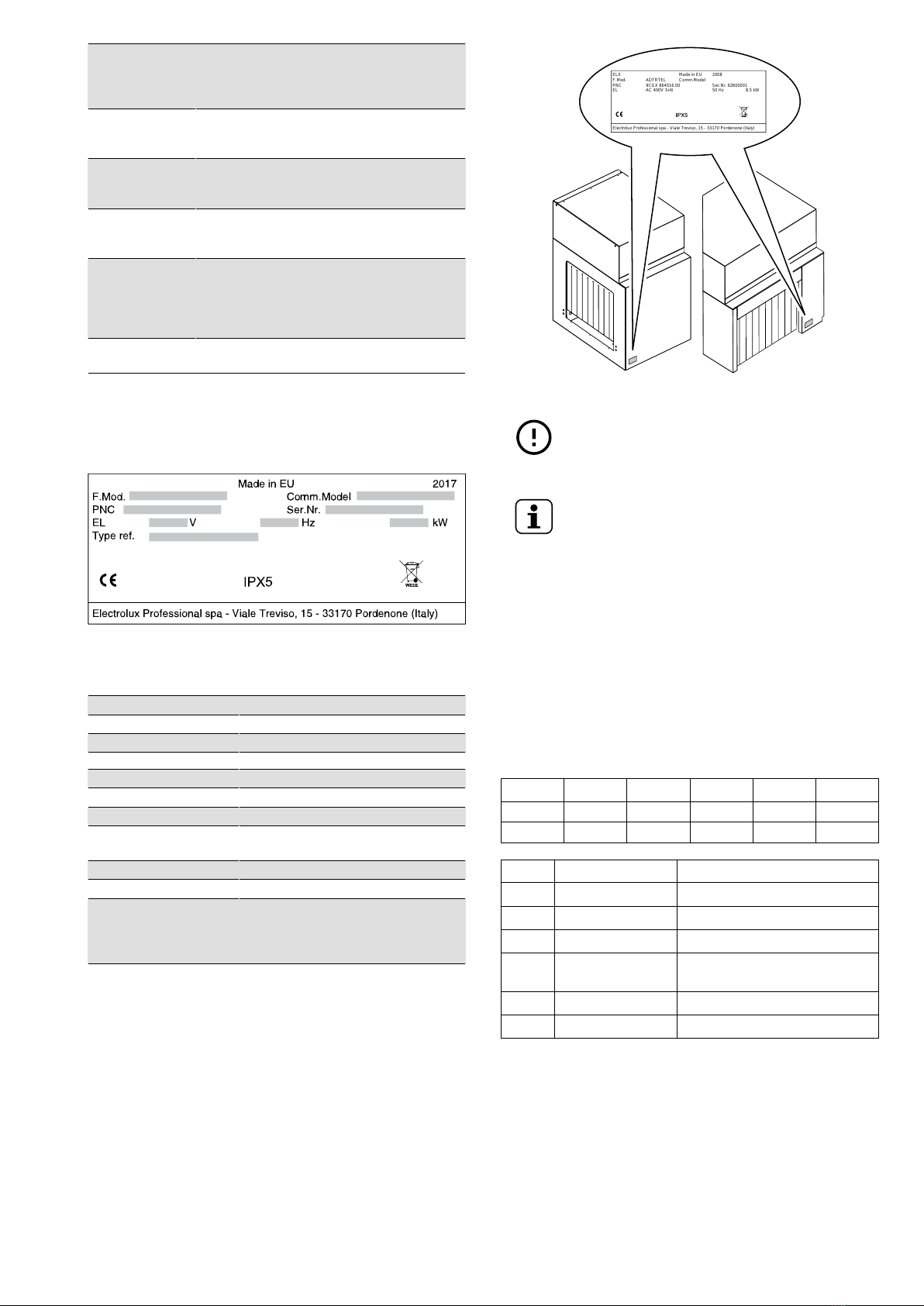
B.3 Appliance and manufacturer's identification data ............................................................................... 15
B.4 Additional indications................................................................................................................... 15
B.4.1 How to interpret the factory description .................................................................................. 15
B.5 Responsibility ............................................................................................................................ 15
B.6 Copyright.................................................................................................................................. 16
B.7 Keeping the manual .................................................................................................................... 16
B.8 Recipients of the manual .............................................................................................................. 16
B.9 Coupling to the rack-type dishwasher.............................................................................................. 16
C TECHNICAL DATA............................................................................................................................... 16
C.1 Main technical characteristics........................................................................................................ 16
C.2 Characteristics of power supply ..................................................................................................... 16
D TRANSPORT, HANDLING AND STORAGE .............................................................................................. 16
D.1 Introduction............................................................................................................................... 16
D.2 Handling................................................................................................................................... 17
D.2.1 Procedures for handling operations....................................................................................... 17
D.2.2 Shifting ........................................................................................................................... 17
D.2.3 Placing the load................................................................................................................ 17
D.3 Storage .................................................................................................................................... 17
D.4 Customer packaging checks ......................................................................................................... 17
E INSTALLATION AND ASSEMBLY ........................................................................................................... 17
E.1 Introduction............................................................................................................................... 17
E.2 Customer responsibilities ............................................................................................................. 17
E.3 Installation of dryer module on the rack-type dishwasher ..................................................................... 17
E.4 Characteristics of the place of machine installation ............................................................................ 17
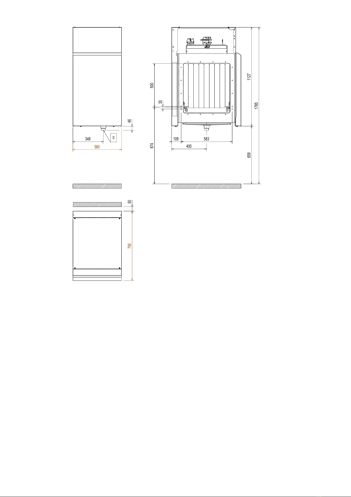
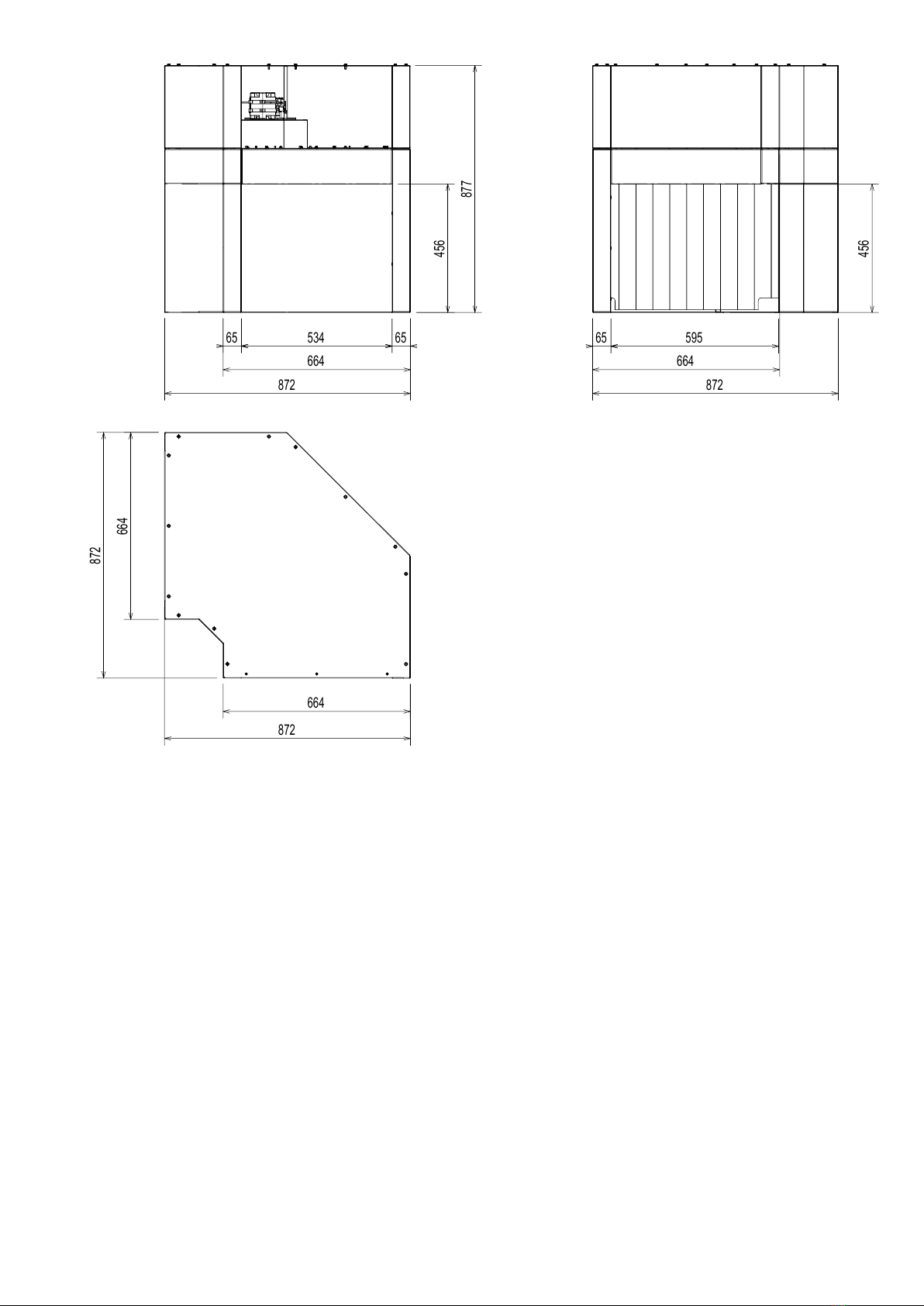
E.5 Appliance space limits ................................................................................................................. 17
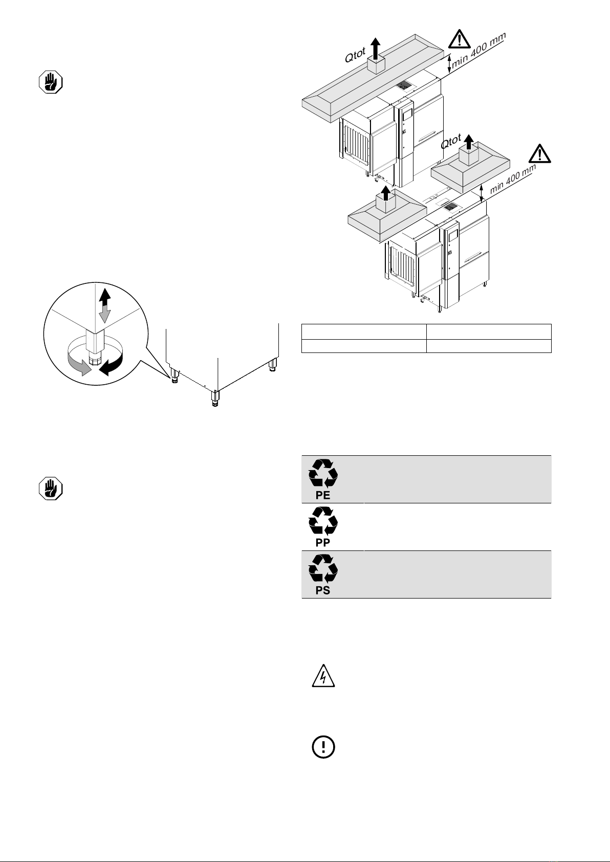
E.6 Positioning ................................................................................................................................ 18
E.7 Extraction hood.......................................................................................................................... 18
E.8 Disposal of packing..................................................................................................................... 18
E.9 Mechanical connections............................................................................................................... 18
E.10 Drying tunnel 22″........................................................................................................................ 19
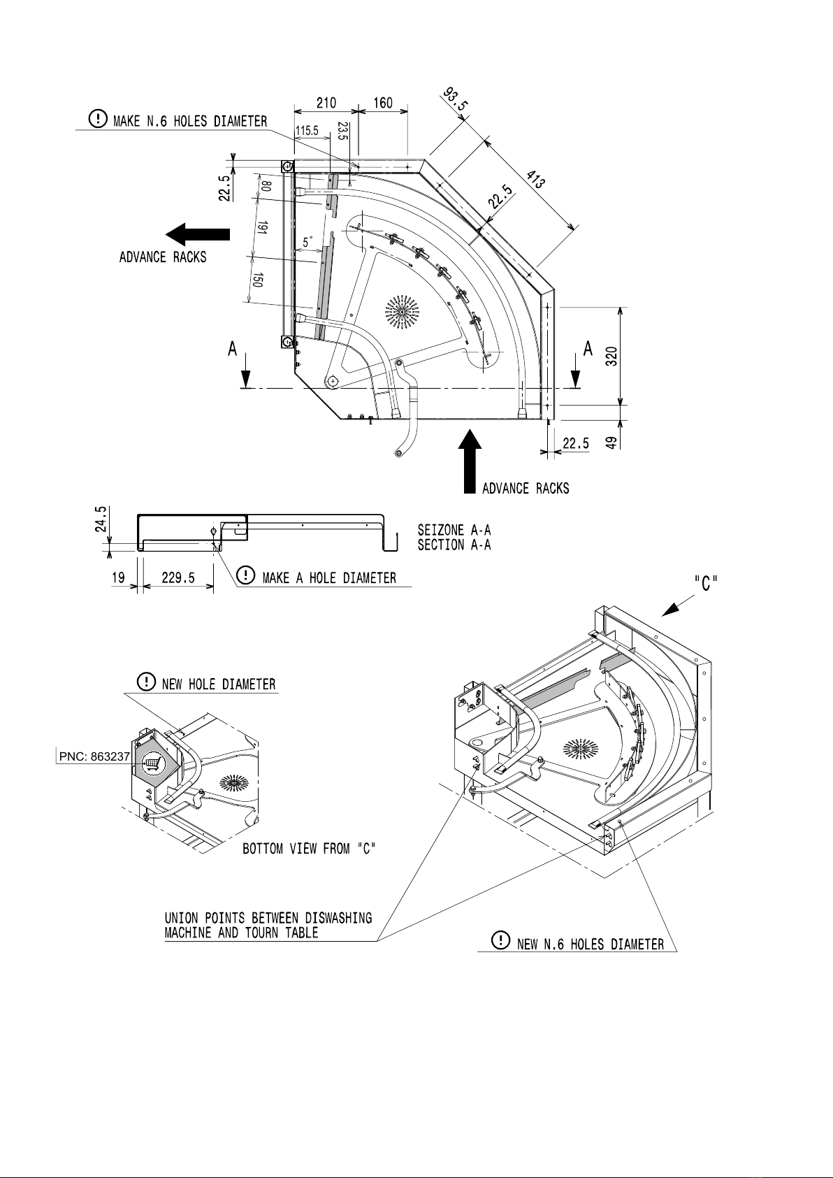
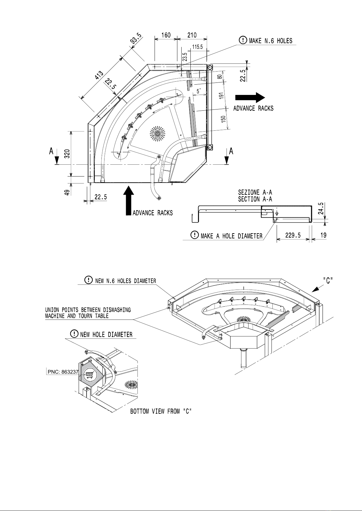
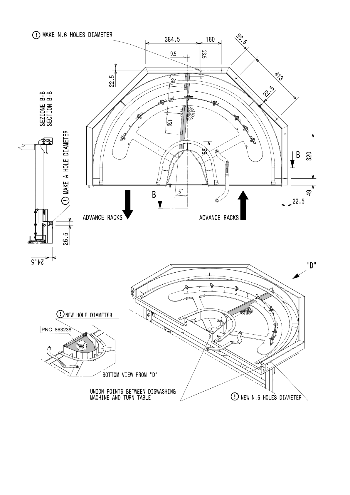
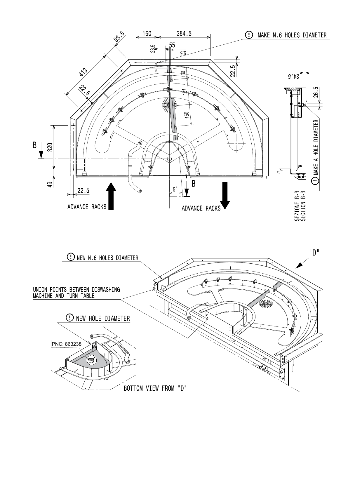
E.11 Drying tunnel corner 90°............................................................................................................... 20
E.11.1 Mechanical connection....................................................................................................... 20
E.11.2 Drilling diagrams for Electrolux rack handling system ................................................................ 22
E.12 Electrical connection ................................................................................................................... 22
E.13 Installation wizard....................................................................................................................... 22
E.14 Constructional modifications ......................................................................................................... 23
E.15 Installation of rack handling systems............................................................................................... 23
E.16 Arrangement for mechanical connection (only for Electrolux Professional rack handling system non motor
operated).................................................................................................................................. 23
E.17 Installation of the end limit switch ................................................................................................... 24
E.17.1 Prearrangement for electrical connection ............................................................................... 24
E.18 Positioning of emergency switches ................................................................................................. 24
E.18.1 Electrical connection.......................................................................................................... 25
E.19 Emergency stop reinstatement ...................................................................................................... 25
E.20 Fitting curtains ........................................................................................................................... 26
F COMMISSIONING ............................................................................................................................... 26
F.1 Preliminary checks, adjustments and operational tests ....................................................................... 26
F.2 Electrical and plumbing connection................................................................................................. 26
F.3 Positioning and fitting of the curtains ............................................................................................... 27
F.4 First starting .............................................................................................................................. 27
G NORMAL USE .................................................................................................................................... 27
G.1 For additional information, refer to manual supplied with the appliance ................................................... 27

11
A SAFETY INFORMATION
A.1 General information
These appliance is intended to be used for commercial applications, for example in
kitchens of restaurant, canteens, hospitals. It must be used for washing or drying
(depending on the model) plates, dishes, glassware, cutlery and similar articles.
To ensure safe use of the appliance and a proper understanding of the manual it is
necessary to be familiar with the terms and typographical conventions used in the
documentation. The following symbols are used in the manual to indicate and identify the
various types of hazards:
WARNING
Danger for the health and safety of operators.
WARNING
Danger of electrocution - dangerous voltage.
CAUTION
Risk of damage to the appliance or the product.
IMPORTANT
Important instructions or information on the product
Equipotentiality
Read the instructions before using the appliance
Clarifications and explanations
A.2 General safety
• The machine must not be used by people (including children) with limited physical,
sensory or mental abilities or without experience and knowledge of it, unless instructed
in its use and supervised by those responsible for their safety.
– Do not let children play with the machine.
– Keep all packaging and detergents away from children.
– Cleaning and user maintenance shall not be made by children without supervision.
• This appliance can be used by children aged from 8 years and above and persons with
reduced physical, sensory or mental capabilities or lack of experience and knowledge if
they have been given supervision or instruction concerning use of the appliance in a
safe way and understand the hazards involved.
• For suitable personal protection equipment, refer to chapter “A.3 Personal protection
equipment“.
• Several illustrations in the manual show the machine, or parts of it, without guards or
with guards removed. This is purely for explanatory purposes. Do not install the machine
without the guards or with the protection devices deactivated.
• Do not remove, tamper with or make illegible the safety, danger and instruction signs
and labels on the machine.

12
• Do not remove or tamper with the machine’s safety devices.
• Before carrying out any machine installation, always consult the installation manual,
which gives the correct procedures and contains important information on safety.
• Unauthorized personnel must not enter the work area.
• Remove any flammable products or items from the work area.
• Machine positioning, installation and disassembly must be carried out by the specialised
personnel in conformity with the current safety regulations, regarding the equipment
used and the operating procedures.
A.3 Personal protection equipment
Summary table of the Personal Protection Equipment (PPE) to be used during the various
stages of the appliance's service life.
Stage Protective
garments
Safety
footwear
Gloves Glasses Safety
helmet
Transport —● ○ —○
Handling ● ● ○ — —
Unpacking ○ ● ○ —
Installation ○ ● ●1— —
Normal use ● ● ●2○—
Adjustments ○ ● — — —
Routine
cleaning
○ ● ●1ˉ3○—
Extraordi-
nary
cleaning
○ ● ●1ˉ3○—
Maintenance ○ ● ○ — —
Dismantling ○ ● ○ ○ —
Scrapping ○ ● ○ ○ —
Key:
●PPE REQUIRED
○PPE AVAILABLE OR TO BE USED IF NECESSARY
—PPE NOT REQUIRED
1. During these operations, gloves must be cut-resistant. Failure to use the personal protection equipment by
operators, specialized personnel or users can involve exposure to damage to health (depending on the model).
2. During these operations, gloves must be heatproof and suitable for contact with water and the substances
used (refer to the safety data sheet of the substances used for the information regarding the required PPE).
Failure to use the personal protection equipment by operators, specialised personnel or users can involve
exposure to chemical risk and cause possible damage to health (depending on the model).
3. During these operations, gloves must be suitable for contact with chemical substances used (refer to the
safety data sheet of the substances used for information regarding the required PPE). Failure to use the
personal protection equipment by operators, specialized personnel or users can involve exposure to chemical
risk and cause possible damage to health (depending on the model).

13
A.4 Transport, handling and storage
• Due to their size, the machines cannot be stacked on top of each other during transport,
handling and storage; this eliminates any risks of loads tipping over due to stacking.
• Do not stand under suspended loads during loading or unloading operations.
Unauthorized personnel must not enter the work area.
• The weight of the appliance alone is not sufficient to keep it steady.
• For machine lifting and anchoring, do not use movable or weak parts such as: casings,
electrical raceways, pneumatic parts, etc.
• Do not push or pull the machine to move it, as it may tip over. Use proper tool to lift the
machine.
• Machine transport, handling and storage personnel must be adequately instructed and
trained regarding the use of lifting systems and personal protection equipment suitable
for the type of operation carried out.
A.5 Installation and assembly
• Follow the installation instruction supplied with the machine.
• Do not install a damaged machine. Any missing or faulty parts must be replaced with
original parts.
• Do not make any modifications to the parts supplied with the machine.
• Disconnect the machine from the power supply before carrying out any installation
procedure. Connect the machine to the power supply only at the end of the installation.
• The machine is not suitable for installation outdoors and/or in places exposed to
atmospheric agents (rain, direct sunlight, freeze, humid and dusty location, etc.).
• Do not install the machine over 2000 meters above sea level.
• Make sure that the floor where you install the machine is flat, stable, heat resistant and
clean.
• If available, make sure to install the accessory to fix the machine to the floor.
• Use a ladder with suitable protection for work on machines with high accessibility.
A.6 Electrical connection
• Work on the electrical systems must only be carried out by a specialised personnel.
• Make sure that the electrical information on the rating plate agrees with the power supply.
• Make sure to install the machine in accordance with the safety regulations and local
laws of the country where used.
• If the power cable is damaged it must be replaced by the Customer Care Service or in
any case by specialised personnel, in order to prevent any risk.
• The machine must be correctly earthed. The manufacturer is not responsible for the
consequences of an inadequate earthing system.
• If present, connected the machine to the equipotential protection circuit .
• To protect the power supply of the machine against short circuits and/or overloads,
install a thermal fuse or a suitable automatic thermal magnetic circuit breaker, ADS
(Automatic Disconnection of Supply).
• To protect the power supply of the machine against current leakages, install a high-
sensitivity manual reset RCD (Residual Current Device), suitable for overvoltage
category III.
• For protection against indirect contacts (depending on the type of supply provided for
and connection of earths to the equipotential protection circuit ) refer to point 6.3.3 of
EN 60204-1 (IEC 60204-1) with the use of protection devices that ensure automatic cut-
off of the supply in case of isolation fault in the TN or TT systems or, for IT systems, the

14
use of isolation controllers or differential current protection devices to activate automatic
power disconnection (an isolation controller must be provided for indicating a possible
first earth fault of a live part, unless a protection device is supplied for switching off the
power in case of a such a fault. This device must activate an acoustic and/or visual
signal which must continue for the entire duration of the fault). For example: in a TT
system, a residual current device with cut-in current (e.g. 30 mA) coordinated with the
earthing system of the building where the machine is located must be installed ahead of
the supply.
• On all rack type dishwasher, make sure to install an emergency switch at the infeed and
outfeed. For all additional modules installed later, move the emergency switch at the
ends of the equipment.
• For all the additional modules installed later, make sure that the power cable supply is
properly sized.
A.7 Service
• Only original spare parts can ensure the safety standards of the appliance.
A.8 Disposal of packing
• Dispose of each packaging items respecting the current regulation in the country of
installation.
A.9 Machine disposal
• Work on the electrical equipment must only be carried out by a specialised personnel,
with the power supply disconnected.
• Dismantling operations must be carried out by specialised personnel.
• Make the appliance unusable by removing the power cable and any compartment
closing devices, to prevent the possibility of someone becoming trapped inside.
• Refer to “A.3 Personal protection equipment“ for suitable personal protection equipment.
• When scrapping the machine, the “CE“ marking, this manual and other documents
concerning the appliance must be destroyed.
IMPORTANT
Save these instructions carefully for further consultation by the various
operators.
B GENERAL INFORMATION
B.1 Introduction
This manual contains information relevant to various applian-
ces. The product images in this guide are only an example.
The drawings and diagrams given in the manual are not in
scale. They supplement the written information with an outline,
but are not intended to be a detailed representation of the
appliance supplied.
The numerical values given on the appliance installation
diagrams refer to measurements in millimeters and/or inches.
B.2 Definitions
Listed below are the definitions of the main terms used in the
manual. It is advisable to read them carefully before use.
Operator machine installation, adjustment, use,
maintenance, cleaning, repair and trans-
port personnel.
Manufacturer Electrolux Professional SpA or any other
service centre authorised by Electrolux
Professional SpA.
Operator for
normal
machine use
an operator who has been informed and
trained regarding the tasks and hazards
involved in normal machine use.
Customer
Care service
or specialised
technician
an operator instructed/trained by the
Manufacturer and who, based on his
professional and specific training, experi-
ence and knowledge of the accident-
prevention regulations, is able to appraise
the operations to be carried out on the
machine and recognise and prevent any
risks. His professionalism covers the
mechanical, electrotechnical and elec-
tronics fields.
Danger source of possible injury or harm to health.
Hazardous
situation
any situation where an operator is
exposed to one or more hazards.
Risk a combination of probabilities and risks of
injury or harm to health in a hazardous
situation.

15
Protection
devices
safety measures consisting of the use of
specific technical means (guards and
safety devices) for protecting operators
against risks.
Guard an element of a machine used in a specific
way to provide protection by means of a
physical barrier.
Safety device a device (other than a guard) that elimi-
nates or reduces the risk; it can be used
alone or in combination with a guard.
Customer the person who purchased the machine
and/or who manages and uses it (e. g.
company, entrepreneur, firm).
Emergency
stop device
a group of components intended for the
emergency stop function; the device is
activated with a single action and pre-
vents or reduces damage to persons/
machines/property/animals.
Electrocution an accidental discharge of electric current
on a human body.
B.3 Appliance and manufacturer's
identification data
An example of the marking or data plate on the machine is
given below:
The data plate gives the product identification and technical
data. The meaning of the various information given on it is
listed below:
F.Mod. factory description of product
Comm.Model commercial description
PNC production number code
Ser.Nr. serial number
V power supply voltage
Hz power supply frequency
kW max. power input
Type ref. list of acronyms used to identify the
type of machine, uniquely
IPX5 dust and water protection rating
CE CE marking
Electrolux Professio-
nal SpA Viale Treviso
15 33170 Pordenone
Italy
manufacturer
The data plate is located on the front panel of the equipment.
Fig. 1 Data plate position
IMPORTANT
When installing the appliance, make sure the
electrical connection is carried out in compliance
with that specified on the data plate.
NOTE!
Refer to the data given on the machine's data plate
for relations with the Manufacturer (e.g. when
ordering spare parts, etc.).
B.4 Additional indications
The drawings and diagrams given in the manual are not in
scale. They supplement the written information with an outline,
but are not intended to be a detailed representation of the
machine supplied
The numerical values given on the machine installation
diagrams refer to measurements in millimeters and/or inches.
B.4.1 How to interpret the factory description
The factory description on the data plate has the following
meaning:
(1) (2) (3) (4) (5) (6)
N M H SDR E 56
N C D SDR E 56
Description Possible variables
(1) Mark Multibrand
(2) Module Lenght M = 22″; C = corner 90°
(3) Type of module H = hot air blower; D = dryer
(4) Type of
application
SDR = single and dual rinse
(5) Supply E = Electric
(6) Frequency 50/60 Hz
B.5 Responsibility
The Manufacturer declines any liability for damage and
malfunctioning caused by:
• non-compliance with the instructions contained in this
manual;
• repairs not carried out in a workmanlike fashion, and
replacements with parts different from those specified in
the spare parts catalogue (the fitting and use of non-original
spare parts and accessories can negatively affect appliance
operation and invalidates the original manufacturer
warranty);
ELX Made in EU 2008
F.Mod. ADTRTEL Comm.Model
PNC 9CGX 86456 00 Ser.Nr. 6260000
EL AC 400V 3+N 50 Hz 8.5 kW
Electrolux Professional spa - Viale Treviso, 5 - 3370 Pordenone (Italy)

16
• operations carried out by non-specialised personnel;
• unauthorized modifications or operations;
• missing, lack or inadequate maintenance;
• improper appliance use;
• unforeseeable extraordinary events;
• use of the appliance by uninformed and / or untrained
personnel;
• non-application of the current provisions in the country of
use, concerning safety, hygiene and health in the workplace.
The Manufacturer declines any liability for damage caused by
arbitrary modifications and conversions carried out by the user
or the Customer.
The employer, workplace manager or service technician are
responsible for identifying and choosing adequate and suitable
personal protection equipment to be worn by operators, in
compliance with regulations in force in the country of use.
The Manufacturer declines any liability for inaccuracies con-
tained in the manual, if due to printing or translation errors.
Any supplements to the installation, use and maintenance
manual the Customer receives from the Manufacturer will form
an integral part of the manual and therefore must be kept
together with it.
B.6 Copyright
This manual is intended solely for consultation by the operator
and can only be given to third parties with the permission of
Electrolux Professional SpA company.
B.7 Keeping the manual
The manual must be carefully kept for the entire life of the
appliance, until scrapping. The manual must stay with the
appliance in case of transfer, sale, hire, granting of use or
leasing.
B.8 Recipients of the manual
This manual is intended for:
• the carrier and handling personnel;
• installation and commissioning personnel;
• specialised personnel - Customer Care service (see service
manual).
B.9 Coupling to the rack-type dishwasher
The Manufacturer provides for the possibility of equipping the
rack-type dishwashers included in the Electrolux Professional
SpA product catalogue with the drying tunnel systems referred
to in this manual, with the possibility of obtaining various
configurations.
The “CE“ Declaration of conformity coming with the rack-type
dishwasher also provides for these configurations.
The Manufacturer provides for the possibility of connecting the
drying tunnel to rack-type dishwashers made exclusively by
Electrolux Professional SpA. The Manufacturer does not
provide for the possibility of making other types of product
combinations (to create a series of machines arranged and
controlled in an integral way) with systems different from that
described above. The Manufacturer declines any liability for
damage caused by arbitrary modifications and conversions
carried out by the user or third parties. For requests or for
further information, contact Electrolux Professional S.p.A. - Via
Treviso, 15 - 33170 Pordenone - Italy.
C TECHNICAL DATA
C.1 Main technical characteristics
Model DT 22″ DT 90°
Power supply Electric Electric
Power supply voltage V 380 - 415 3N~ 380 - 415 3N~
Frequency Hz 50/60 50/60
Max. power. absorbed kW 4.4 4.4
Temperature ℃70 70
Protection rating IPX5 IPX5
Net weight kg 75 65
Air flow m3/h 540 540
Ventilation motor power kW 0.12 0.12
Current absorbed by fan A 0.51 0.51
Heating element kW 4.13 4.13
Legal noise level Leq dB(A) LpA:70dB - KpA:1.5dB1LpA:70dB - KpA:1.5dB1
1. The noise emission values have been obtained according to EN ISO 11204.
C.2 Characteristics of power supply
The AC power supply to the machine must meet the following conditions:
• max. voltage variation ± 6%
• max. frequency variation ± 1% continuous ± 2% for a short period.
Harmonic distorsion, unbalanced three-phase supply voltage, voltage pulses, interruption, dips and the other electric character-
istics must respect the provisions of point 4.3.2 of Standard EN 60204-1 (IEC 60204-1).
D TRANSPORT, HANDLING AND STORAGE
WARNING
Refer to “Safety Information“.
D.1 Introduction
Transport (i. e. transfer of the appliance from one place to
another) and handling (i. e. transfer inside workplaces) must
occur with the use of special and adequate means.

17
CAUTION
The appliance must only be transported, handled and
stored by specialised personnel, who must have:
• specific technical training and experience in the use of
lifting systems;
• knowledge of the safety regulations and applicable laws
in the relevant sectors;
• knowledge of the general safety rules;
• personal protection equipment suitable for the type of
operation carried out;
• the ability to recognize and avoid any possible hazard.
IMPORTANT
Immediately check for any damage caused during
transport.
Inspect the packaging before and after unloading.
D.2 Handling
Arrange a suitable area with flat floor for appliance unloading
and storage operations.
D.2.1 Procedures for handling operations
Before lifting:
• send all operators to a safe position and prevent persons
from entering the handling area;
• make sure the load is stable;
• make sure no material can fall during lifting. Manoeuvre
vertically in order to avoid impacts;
• handle the appliance, keeping it at minimum height from the
ground.
For correct and safe lifting operations:
• use the type of equipment most suitable for characteristics
and capacity (e.g. electric pallet truck or lift truck);
• cover sharp edges;
• check the forks and lifting procedures according to the
instructions given on the packing.
D.2.2 Shifting
The operator must:
• have a general view of the path to be followed;
• stop the manoeuvre in case of hazardous situations.
D.2.3 Placing the load
• Before placing the load, make sure the way is free and that
the floor is flat and can take the load.
• Remove the appliance from the wooden pallet, move it to
one side, then slide it onto the floor.
D.3 Storage
The appliance and/or its parts must be stored and protected
from damp, in a non-aggressive place, free of vibrations and
with room temperatures between -10℃[14℉] and 50℃
[122℉].
The place where the appliance is stored must:
• can take the appliance load,
• have a flat support surface to avoid deforming the appliance
or damage to the support feet.
D.4 Customer packaging checks
• The forwarder is responsible for the goods during transport
and delivery.
• Make a complaint to the forwarder in case of visible or
hidden damage.
• Specify any damage or shortages on the dispatch note.
• The driver must sign the dispatch note: the forwarder can
reject the claim if the dispatch note is not signed (the
forwarder can provide the necessary form).
• For hidden damage or shortages becoming apparent only
after unpacking, request the forwarder for inspection of the
goods within and no later than 15 days after delivery.
After packaging checks
1. Remove the packaging.
Take care when unpacking and handling of the appliance
to not cause any shocks on itself.
2. Keep all the documentation contained in the packaging.
E INSTALLATION AND ASSEMBLY
WARNING
Refer to “Safety Information“.
E.1 Introduction
WARNING
Make sure that the switch disconnector of the
machine is locked in the Off position - “O“.
E.2 Customer responsibilities
The Customer must provide for the following:
• installation of an adequate electrical power supply ahead of
the appliance, according to the equipment’s technical
specifications (C TECHNICAL DATA and C.2 Character-
istics of power supply);
• adducting for the electrical connection between the work-
place electric panel and the equipment;
• the water supply and drain connections and other con-
nections as indicated in the technical data table and in the
installation diagram;
• arrangement of general workplace lighting to guarantee at
least 500 lx according to point 5.2.2 of EN 12464-1 or
according to a value established by the current regulations
in the country of use;
• the addition of the drying module changes the arrangement
of the emergency stops. This arrangement must be re-
examined (E.18 Positioning of emergency switches).
E.3 Installation of dryer module on the rack-
type dishwasher
The Manufacturer provides for the possibility of connecting the
drying tunnel only to rack-type dishwashers included in the
Electrolux Professional SpA catalogue.
E.4 Characteristics of the place of machine
installation
This additional module is designed for installation in profes-
sional and not domestic-type kitchens (for installation of the
entire machine, refer to the rack-type dishwasher instruction
manual). For this module, water collection traps/metal grates
must be arranged in the floor at the machine discharges (refer
to “ Installation diagram“), possibly replaceable with a single
water trap sized for a flow rate of at least 3 l/s.
E.5 Appliance space limits
• A suitable space must be left around the machine (for
operations, maintenance, for a correct air exchange, etc.).

18
• This space must be increased in case of use and/or transfer
of other equipment and/or means or if exit routes are
necessary inside the workplace.
CAUTION
• Install the machine at a distance of not
less than 50 mm from the wall so as not
to affect correct ventilation of internal
components.
• For the machine with heat pump, make
sure that the distance from the ceiling is
not less than 300 mm.
E.6 Positioning
Unless otherwise agreed, the drying tunnel is supplied in a
single unit. The drying tunnel must be taken to the place of
installation and the packing base removed only when being
installed.
• Position the drying tunnel in the required place.
• Depending on the model, adjust the equipment by turning
the special adjustable feet.
• Fix the drying tunnel to the existing dishwasher.
The installer must carefully follow the installation
instructions.
• Carefully remove the protective film from the outer panels
without tearing it, to avoid leaving traces of glue.
CAUTION
The gravity centre of drying tunnel does
not coincide with its geometric centre.
E.7 Extraction hood
Make sure to position the possible extraction hood at a
distance of not less than 400 mm from the machine so as not
to compromise machine operation.
The extractor hood is installed to remove the steam emitted by
the machine. The hood air delivery must be calculated taking
into account the machine model, the type of installation and the
work environment where installed.
Model Qtot (VDI2052)
...SR10E... 1500 m3/h
E.8 Disposal of packing
The packing must be disposed of in compliance with the
current regulations in the country where the appliance is used.
All the packing materials are environmentally friendly.
They can be safely kept, recycled, or burned in an appropriate
waste incineration plant. Recyclable plastic parts are marked
as follows:
Polyethylene
• Outer wrapping
• Instructions bag
Polypropylene
• Straps
Polystyrene foam
• Corner protectors
The parts in wood and cardboard can be disposed of,
respecting the current regulations in the country where the
appliance is used.
E.9 Mechanical connections
WARNING
Make sure that the switch dis-
connector of the machine is
locked in the Off position - “O“.
IMPORTANT
The drying tunnels 90° and 22″ must be lifted and
positioned by two people: accident risk due to
excessive weight.
Qtot
min 400 mm
min 400 mm
Qtot

19
CAUTION
• Refer to “A.3 Personal protection
equipment“ for suitable personal pro-
tection equipment. Use gloves and
other personal protection equipment
according to the risks present (e. g.
glasses in case of risk of flying splinters
during drilling).
• Install only Electrolux Professional rack
handling system (non-motor-operated).
NOTE!
To install the drying tunnel in a left to right machine,
refer to the corresponding instructions provided.
E.10 Drying tunnel 22″
Joining kit list
118 screws (M6x14mm), 36 washers (⌀=6x18mm),
18 cap nuts (⌀=6mm)
22 connection bracket and 8 flange nuts (⌀=5mm)
3Connection hose for water draining
4Drain
5Pins and nuts to fix the slide of the dryer to the slide
of the machine
1. Remove the side panels “1-2“ from the machine.
2. Install the connection bracket on the ⌀=5 mm stud bolts of
the dryer roof. Firmly secure the brackets with ⌀=5 mm
flange nuts.
3. Place the drying tunnel near the machine.
IMPORTANT
Make sure the modules are correctly aligned. If
necessary use a pallet trucks to make easy this
operation.
4. Join the module openings with the bolts, washer and nuts
(see detail “A“).
5. Firmly secure the connection brackets on the roof of the
dryer and machine with ⌀=5 mm flange nuts (see detail
“B“).
1
2
3
4
5
1
2
kg
x2
18x
A
B

20
6. Install the drain in the dryer to discharge the residual water.
7. Connect the drain outlet of the dryer and the machine with
the supplied connection hose.
IMPORTANT
Make sure to remove the plug at the end of the
drain connection hose.
8. Insert the slide for basket (see detail “C“). Fix the slide of
the dryer to the slide of the machine (see detail “D“).
9. Refit the side panels “1-2“ on the drying tunnel side.
E.11 Drying tunnel corner 90°
CAUTION
Install only Electrolux rack handling
system (non-motor-operated).
NOTE!
This drying tunnel can be coupled to a 90° or 180°
turntable.
E.11.1 Mechanical connection
Joining kit list
12 Adjustable feet
27 self tapping screws (4,2 x 9,5 mm)
32 side brackets and 6 screws (5 x 14 mm)
4Top bracket and 8 flange nuts (⌀=5mm)
C
D
1
2
1
2
3
4
This manual suits for next models
1
Table of contents
Other Electrolux Professional Dishwasher manuals