manuals.online logo
Brands
  1. Home
  2. •
  3. Brands
  4. •
  5. Electrolux
  6. •
  7. Refrigerator
  8. •
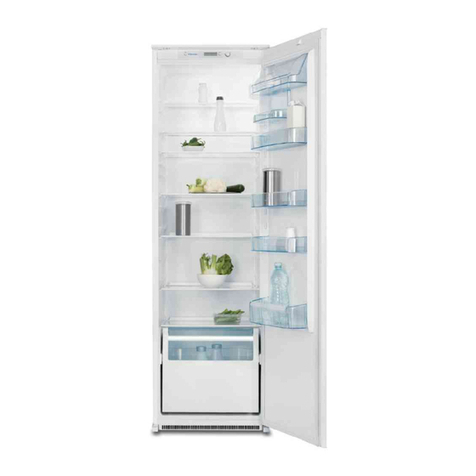
  9. Electrolux TCW 1990 User manual

Electrolux TCW 1990 User manual

Other manuals for TCW 1990

1

Other Electrolux Refrigerator manuals

Electrolux ERB 25291 W8 User manual

Electrolux

Electrolux ERB 25291 W8 User manual

Electrolux ERZ28801 User manual

Electrolux

Electrolux ERZ28801 User manual

Electrolux SK23113 User manual

Electrolux

Electrolux SK23113 User manual

Electrolux LNC7ME32W4 User manual

Electrolux

Electrolux LNC7ME32W4 User manual

Electrolux EW23BC85KS User manual

Electrolux

Electrolux EW23BC85KS User manual

Electrolux LNT3LF34W3 User manual

Electrolux

Electrolux LNT3LF34W3 User manual

Electrolux ZANUSSI ZEBF 351 W User manual

Electrolux

Electrolux ZANUSSI ZEBF 351 W User manual

Electrolux FI291/2TS User manual

Electrolux

Electrolux FI291/2TS User manual

Electrolux ERC3200 User manual

Electrolux

Electrolux ERC3200 User manual

Electrolux ERD 6843 User manual

Electrolux

Electrolux ERD 6843 User manual

Electrolux IK327SA User manual

Electrolux

Electrolux IK327SA User manual

Electrolux IK305BNL User manual

Electrolux

Electrolux IK305BNL User manual

Electrolux Built-In Dishwasher User manual

Electrolux

Electrolux Built-In Dishwasher User manual

Electrolux ERY1201FOW User manual

Electrolux

Electrolux ERY1201FOW User manual

Electrolux EBB2600MG User manual

Electrolux

Electrolux EBB2600MG User manual

Electrolux JUNO JRG 94126 User manual

Electrolux

Electrolux JUNO JRG 94126 User manual

Electrolux OptiSpace LRB2AE88S User manual

Electrolux

Electrolux OptiSpace LRB2AE88S User manual

Electrolux EA0300C Quick guide

Electrolux

Electrolux EA0300C Quick guide

Electrolux Cold Rooms 102028 User manual

Electrolux

Electrolux Cold Rooms 102028 User manual

Electrolux ENG2913AOW User manual

Electrolux

Electrolux ENG2913AOW User manual

Electrolux ERF4162AOW User manual

Electrolux

Electrolux ERF4162AOW User manual

Electrolux ERC 2723 User manual

Electrolux

Electrolux ERC 2723 User manual

Electrolux ERC 25391 W8 User manual

Electrolux

Electrolux ERC 25391 W8 User manual

Electrolux Freezer User manual

Electrolux

Electrolux Freezer User manual

Popular Refrigerator manuals by other brands

Frigidaire FRS26TS7DW2 Use & care manual

Frigidaire

Frigidaire FRS26TS7DW2 Use & care manual

Fisher Scientific 10ECEEFSA manual

Fisher Scientific

Fisher Scientific 10ECEEFSA manual

Summit FF22BDRSS user manual

Summit

Summit FF22BDRSS user manual

Frigidaire FFRU17B2QWE use & care

Frigidaire

Frigidaire FFRU17B2QWE use & care

Hotpoint ENBGH 19xxx FW operating instructions

Hotpoint

Hotpoint ENBGH 19xxx FW operating instructions

Hitachi R-SG28KPH instruction manual

Hitachi

Hitachi R-SG28KPH instruction manual

Dometic RMH 7390 L operating instructions

Dometic

Dometic RMH 7390 L operating instructions

AEG S71700TSW0 user manual

AEG

AEG S71700TSW0 user manual

Beko GNE 60520 X user manual

Beko

Beko GNE 60520 X user manual

Jenn-Air JUR248LBES00 Use & care guide

Jenn-Air

Jenn-Air JUR248LBES00 Use & care guide

Dometic RGE 4000 Installation and operating manual

Dometic

Dometic RGE 4000 Installation and operating manual

Dometic L-0191B Brochure & specs

Dometic

Dometic L-0191B Brochure & specs

LG LRBP1031W - 10 Cu. Ft. Cabinet Depth Bottom Freezer... owner's guide

LG

LG LRBP1031W - 10 Cu. Ft. Cabinet Depth Bottom Freezer... owner's guide

Daewoo RN-33 Series user manual

Daewoo

Daewoo RN-33 Series user manual

Haier RF-8888-174 Service manual

Haier

Haier RF-8888-174 Service manual

Blaupunkt 5CK2 Series user manual

Blaupunkt

Blaupunkt 5CK2 Series user manual

Beko B5RCNE366HG user manual

Beko

Beko B5RCNE366HG user manual

GE TBX21 use and care manual

GE

GE TBX21 use and care manual

manuals.online logo
manuals.online logoBrands
  • About & Mission
  • Contact us
  • Privacy Policy
  • Terms and Conditions

Copyright 2025 Manuals.Online. All Rights Reserved.

820 41 72 58
USER
USERs MANU
s MANUAL -
AL - NO
NOTICE DUTILIS
TICE DUTILISA
ATION -
TION -
MANU
MANUAL DEL USU
AL DEL USUARIO
ARIO
TCW 1990
ICE LINING REFRIGERATOR FREEZER GB
REFRIGERATEUR / CONGELATEUR
A PAROI REFRIGERANTE - ILR
FRIGORIFICO/CONGELADOR
REVESTIDO DE HIELO
F
E
USER MANUAL
2
ICE LINING REFRIGERATOR FREEZER
Handle
Lid ice accu
Rubber gasket
Data label
Thermometer
850
1050
630
1465
Compressor
compartment
Pilot lamp ON
Thermostat for
refrigerator function
Drain plug
Locking device
Interior wall
1. GENERAL INFORMATION ......................................................page 4
2. INSTALLATION .....................................................................page 5-9
3. PREPARATIONS....................................................................page 10-11
4. USE THE APPLIANCE ...........................................................page 12
5. DEFROSTING & CLEANING ..................................................page 13-14
6. PERIODIC OBSERVATIONS/CHECKS/ACTIONS .....................page 15
7. TROUBLE SHOOTING ...........................................................page 16-17
(A) ILR not working
(B) Compressor is working,
but cabinet temperature is higher than normal
(C) Cabinet temperature is lower than normal
(D) Abnormal noise in the ILR
8. SHUTTING DOWN ................................................................page 18
9. STORAGE OF VACCINES IN THE ILR .....................................page 18
INDEX
3
THE ILR
One of the most important links in the cold-chain is Ice
Lining Refrigerator (ILR). This is a unit which operates
on the principle of vapour compression system,
similar to any conventional compressor type
refrigerator operating on 1 15 or 230 volts, A.C. mains
supply. However, the ILR has top opening door to
prevent loss of cold air during door opening.
ICE LINING
The Icelined Refrigerator and Freezer has a icebank
inside the cabinet. The ice bank consists of frozen
icepacks during its operation. During periods of
power failure and load procedures, the ice bank acts
as cold storage to protect the vaccines. The ice bank
keep the temperature is not above +8°C for 30 hours.
HOLD OVER TIME
In case of power failure this unit is capable to hold the
temperature (if all the ice-packs are installed) inside
the Refrigeration compartment between 2 and 8°C
under following conditions.
Ambient temperature: Minimum hold over:
32°C 30 hours
43°C 20 hours
POWER SUPPLY
The ILR is fitted with heavy duty compressor which
requires low starting current and can also operate
within a range of voltage variations.
E.g. if the normal operating voltage is 230 volts, 50
Hz., A.C., it can work even when the supply voltage
occasionally go as low as 150 volts or as high as
280 volts.
THERMOMETER
To enable to measure the temperature inside the
cabinet without opening the lid, a thermometer is
provided with its dial on the front side. This makes
monitoring of the vaccine temperature easy.
LOCKING SYSTEM
The ILR is equipped with a lock, operated with a
key.
POWER-SUPPLY ARRANGEMENT
For smooth functioning of the ILR it is advisable to
connect the same to a 15 Amps power plug socket
outlet, wired from the mains with PVC insulated
cables of minimum 2.5 mm section of Aluminium
(see also page 5 under `Installation'). The larger
size of the plug and socket decreases the contact
resistance which in turn reduces voltage drop and
provides an easy path for the current.
Safety of the personnel and the equipments can not
be guaranteed unless the earth wire (green/yellow)
of the cord is really earthed. It is advisable to have
the earth connections to the socket checked by a
competent electrician.
VOLTAGE STABILIZER
Though the ILR is capable of operating within a
wide range of voltage variations, for extra safety one
separate Automatic Voltage Stabilizer should be
used with it.
1. GENERAL INFORMATION
4
Check the manufacturer's plate, at the back of the ILR
and make sure that the ILR has correct voltage for
local supply, i.e. 1 15 or 230 volts (fig. 1).
CAUTION
Connecting the equipment to wrong supply
voltage may damage it.
If you have received equipments of wrong voltage
ratings, notify concerned authorities and keep the
equipments repacked.
The ILR is to be installed in a well ventilated room,
avoiding direct sunshine or any other source of heat.
Power supply socket (15 amps socket with switch,
fuse and mains indicator lamp is advisable) should be
available nearest to the place of installation of the ILR.
1.
Unscrew and remove the screws holding the side
cover of the compressor compartment on the right
hand side of the ILR and remove carefully the side
cover (fig. 2)
2. INSTALLATION
5
Fig. 2.
Fig. 1.
3.
EXAMINE the compressor compartment (fig. 3;
Check carefully for any damage, dislocation or
looseness etc. of the components, specially at
locations A, B. C, and D as below and rectify if
necessary.
LOCATION A (fig. 4)
Check that all 4 mounting brackets of the compressor
are in place and secured.
2. INSTALLATION
6
Fig. 4.
Fig. 3.
LOCATION B (fig. 5)
Check that the incoming electrical connections of the
power supply cord to the terminal strip are tight.
LOCATION C (fig. 6)
Check that the outgoing electrical connections from
the terminal strip are tight.
LOCATION D (fig. 7)
Check that the mounting brackets of the fan are tight
and also that the fan blades are free to rotate.
2. INSTALLATION
7
Fig. 5.
Fig. 6.
Fig. 7.
8
4.
Refit side cover of the compressor compartment into
position refixing the screws holding the side cover (fig. 8)
5.
INSTALL firmly the ILR on a level
floor, preferably on wooden
blocks or on a wooden platform to
protect it from damp and dirt.
(fig. 5)
Leave sufficient space on all sides
of the ILR, keep it away from the
walls for good circulation of air
around it, see below:
Back and left side should be
minimum 3 cm away from the
walls (fig. 9a)
Hinges can be pushed against the
wall
Right side should be minimum
10 cm away from the wall (fig. 9b)
6.
The ILR has 4 supporting legs. If
the ILR is not in a level and stable
position, adjust this by adding
wooden blocks or similar under
the legs.
2. INSTALLATION
Fig. 8.
Fig. 9.
Fig. 9a
Fig. 9b
9
7.
Connect the leads of the power supply cord to a
suitable 3-pin plug as shown below (fig. 10)
Lead of cord Pin of plug
Green/yellow Earth
Blue Neutral
Brown Phase
CAUTION:
DO NOT CONNECT THE ILR TO POVER SUPPLY
NOW
2. INSTALLATION
Fig. 10.
10
1.
Open the lid of the appliance. Unscrew the the lid
ballast container. (fig. 11)
2.
Unscrew the cap of the lid ice accu and fil it with clean
water.
3.
Unscrew the 3 frame screws and remove the plastic
Refrigerator innerliner. (fig. 12)
4.
Remove all 36 ice-packs from the ice bank and the 5
ice-packs in the refrigeration compartment.
5.
Plug in the appliance for test. The green lamp
indicates that the unit is under power. (fig. 13)
6.
Check in the compressor compartment that the
compressor starts and the fan on the left side is running.
7.
Check that the blower in the bottom of the dividing wall
is running. Check by pushing with your fingers to the
flap thermostat, if a free moving to open and close the
cold air channel is granted.
3. PREPARATIONS
Fig. 11.
Fig. 12.
Fig. 13.