Electron Thermo 3684 Operating instructions

Models:
3684,
3686,
& 3688
Laboratory Refrigerators
Operating and Maintenance Manual
Manual No: 7003688 Rev. 9

Model 3680 Series ____________________________________________________________________
i
Read This Instruction Manual.
Failure to read, understand and follow the instructions in
this manual may result in damage to the unit, injury to operat-
ing personnel, and poor equipment performance.
CAUTION! All internal adjustments and maintenance must
be performed by qualified service personnel.
Refer to the serial tag on the back of this manual.
The material in this manual is for information purposes only. The
contents and the product it describes are subject to change with-
out notice. Thermo Electron Corporation makes no representa-
tions or warranties with respect to this manual. In no event shall
Thermo be held liable for any damages, direct or incidental, aris-
ing out of or related to the use of this manual.
MANUAL NO. 7003688
9 22052/FR-1762 2/2/04 Discontinued Models 3687 and 3689 ccs
8 21443 3/20/03 Removed strip chart recorder as an accessory aks
7 21377/IN-3086 2/13/03 Clarified condenser cleaning ccs
6 20358 10/2/01 Updated specs and refrigeration schematics for refrigerant amount change ccs
5 20201/FR-1531 7/13/01 Revised Section 3.1 refrigerator defrost function aks
4 19174/FR1404 7/31/00 Revised electrical schematics and parts lists aks
3 18542/IN-2738
18682/IN-2752 10/12/99 Updated 3688 schematic to include new defrost sensor 227960
Added schematics for 3687 and 3689 ccp
2 18454/FR-1312 7/19/99 Added breaker switch location ccp
1 18322 5/19/99 Added Models 3684 and 3686 ccp
0 IN-2697 4/15/99 Original manual ccp
REV ECR/ECN DATE DESCRIPTION By
Model 3680 Series ____________________________________________________________________
ii
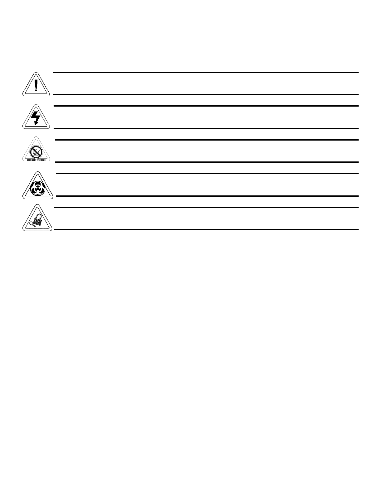
Alerts the user to important operating and/or maintenance instructions. May be used alone or with other safety sym-
bols. Read the accompanying text carefully.
Potential electrical hazards. Only qualified persons should perform the instructions and procedures associated with
this symbol.
Hazard. Do not touch. Instructions associated with this symbol should only be carried out when using special hand-
ing equipment or when wearing special, protective clothing.
Potential biological hazards. Proper protective equipment and procedures must be used when following instructions
associated with this symbol. Reference O.S.H.A. Regulation 1910-1030.
Potentially hazardous energy. Equipment being maintained or serviced must be turned off and locked off to prevent
possible injury. Reference O.S.H.A. Regulation 1910-147.
√ Always use the proper protective equipment (clothing, gloves, goggles, etc.)
√ Always dissipate extreme cold or heat and wear protective clothing.
√ Always follow good hygiene practices.
√ Each individual is responsible for his or her own safety.

Model 3680 Series ____________________________________________________________________
iii


Model 3680 Series ____________________________________________________________________
iv
Table of Contents
Section 1 - Installation and Start-Up . . . . . . . . . . . . . .1 - 1
1.1 Location and Unpacking . . . . . . . . . . . . . . . . . . . . . .1 - 1
1.2 Leveling . . . . . . . . . . . . . . . . . . . . . . . . . . . . . . . . . . .1 - 1
1.3 Connecting to Power . . . . . . . . . . . . . . . . . . . . . . . . .1 - 2
1.4 Installing the Shelves . . . . . . . . . . . . . . . . . . . . . . . . .1 - 2
1.5 Start-Up Procedure . . . . . . . . . . . . . . . . . . . . . . . . . .1 - 2
Section 2 - Control Panel Procedures . . . . . . . . . . . . . .2 - 1
2.1 Temperature Control . . . . . . . . . . . . . . . . . . . . . . . . .2 - 1
2.2 Key Lock Control . . . . . . . . . . . . . . . . . . . . . . . . . . .2 - 2
2.3 High and Low Temperature Alarm . . . . . . . . . . . . . .2 - 2
a. High Temperature Setpoint . . . . . . . . . . . . . . . . . .2 - 2
b. Low Temperature Setpoint . . . . . . . . . . . . . . . . . .2 - 3
2.4 Door Open Light . . . . . . . . . . . . . . . . . . . . . . . . . . . .2 - 3
2.5 Audible Alarm Switch . . . . . . . . . . . . . . . . . . . . . . .2 - 3
2.6 Interior Lights Switch . . . . . . . . . . . . . . . . . . . . . . . .2 - 3
2.7 Digital Temperature Display . . . . . . . . . . . . . . . . . . .2 - 3
2.8 Remote Alarm Terminal . . . . . . . . . . . . . . . . . . . . . . .2 - 3
Section 3 - Maintenance . . . . . . . . . . . . . . . . . . . . . . . . .3 - 1
3.1 Defrosting the Unit . . . . . . . . . . . . . . . . . . . . . . . . . .3 - 1
a. Cycle Defrost . . . . . . . . . . . . . . . . . . . . . . . . . . . . .3 - 1
b. Forced Defrost . . . . . . . . . . . . . . . . . . . . . . . . . . . .3 - 1
3.2 Cleaning Evaporation Tray, Condenser and Filter . . .3 - 1
a. Cleaning the Evaporation Tray . . . . . . . . . . . . . . .3 - 1
b. Cleaning the Condenser . . . . . . . . . . . . . . . . . . . . .3 - 1
c. Cleaning the Condenser Filter . . . . . . . . . . . . . . . .3 - 1
3.3 Cleaning the Unit . . . . . . . . . . . . . . . . . . . . . . . . . . . .3 - 1
3.4 Replacing the Fluorescent Light . . . . . . . . . . . . . . . .3 - 1
Section 4 – Troubleshooting . . . . . . . . . . . . . . . . . . . . . .4 - 1
4.1 Discarding or Taking Refrigerator Out of Service . .4 - 2
Section 5 – Specifications . . . . . . . . . . . . . . . . . . . . . . . .5 - 1
Section 6 - Parts List . . . . . . . . . . . . . . . . . . . . . . . . . . . .6 - 1
Section 7 - Schematics . . . . . . . . . . . . . . . . . . . . . . . . . . .7 - 1
Section 8 - Warranty Information . . . . . . . . . . . . . . . . .8 - 1

Section 1 - Installation and Start-Up
1.1 Location and Unpacking
This unit will operate most efficiently and safely under
these conditions:
• Indoor use
• Altitude up to 6562 ft. (2000m)
• Ambient temperature range 5°C to 40°C
• Maximum relative humidity 80% for temperatures up to
31°C, decreasing linearly to 50% relative humidity at 40°C
• Mains supply voltage fluctuations not to exceed ±10% of
the nominal voltage
• Transient overvoltages according to Installations
Catagories (Overvoltage Categories) II, which is the mini-
mum and normal category
• Pollution Degree 2 in accordance with IEC 664
Locate the unit on a firm, level surface in an area of mini-
mum ambient temperature fluctuation. Avoid installing the unit
near heat-emitting appliances, as heat can shorten component
life and cause inefficient refrigeration.
Avoid placing the unit in a contaminated area with an
excessive amount of dust, or where chemicals or gases are pres-
ent.
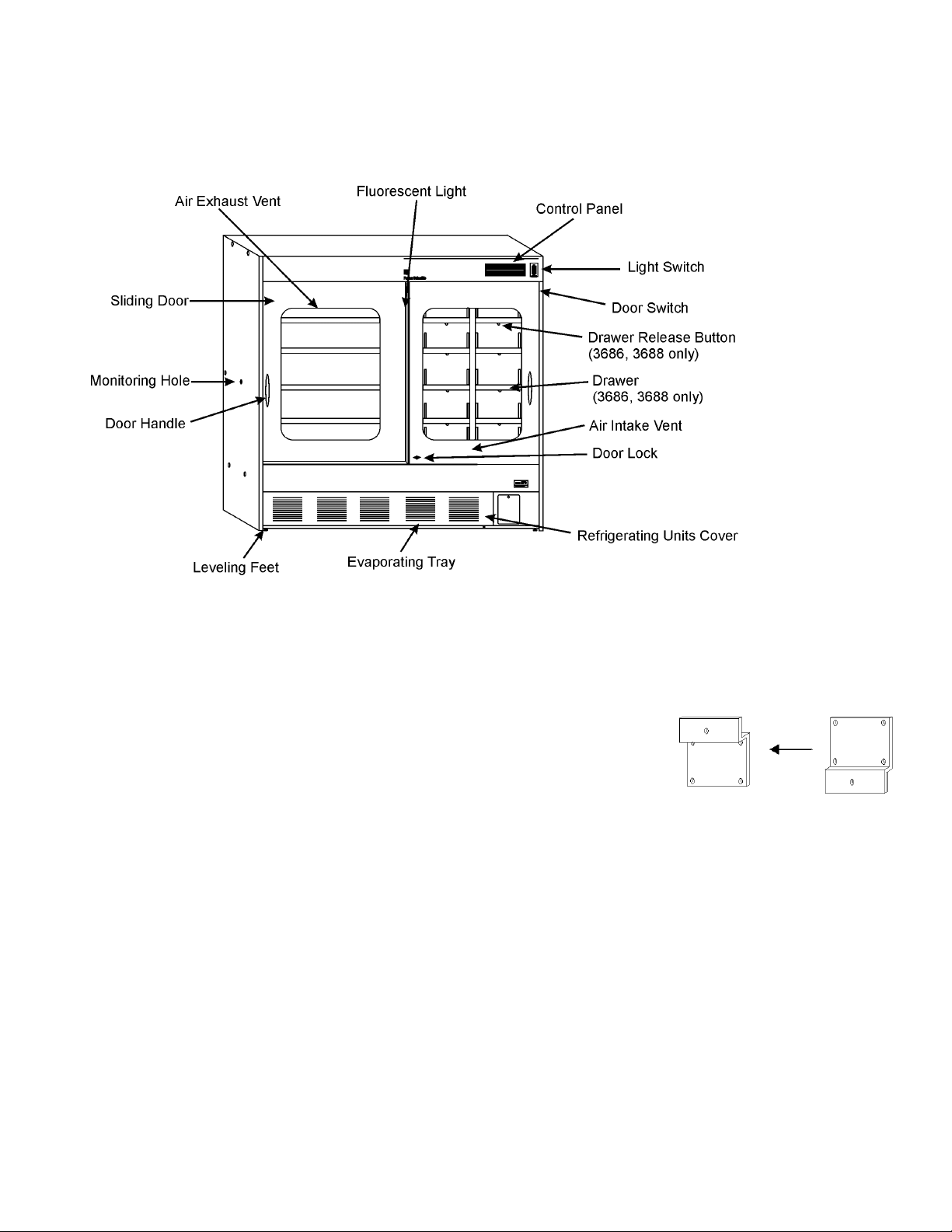
Chamber temperature is maintained through the circulation
of forced air. Ensure that the air intake and exhaust vents are
clear of obstruction at all times. Allow 4-5 inches (10cm) of
clearance on all sides of the unit to reduce power con-
sumption and allow free air circulation.
Two wall mounts are attached to the top rear of the unit.
Remove the wall mounts and reverse their position. Reattach to
the unit. Secure the single hole section of the mount to the wall.
A special bolt-nut is supplied for concrete walls.
Remove all packaging
materials and ventilate the
unit thoroughly.
1.2 Leveling
Adjust the feet on the bottom front of the unit to level the
cabinet. Turn each foot counterclockwise until it makes full
contact with the floor.
1.3 Connecting to Power
Connect the unit to a dedicated, grounded power source
using the three-prong power plug. Refer to the electrical data
plate on the unit for electrical specifications.
Model 3680 Series __________________________________________________________________Installation and Start-Up
1 - 1
1.4 Installing the Shelves
Adjust each shelf position by inserting the shelf support
clips into the slots at the desired level. Make sure that the
shelves are secure before placing product on them.
If the unit is equipped with drawers, press the release but-
ton on the bottom of the drawer to open. The drawer positions
are also adjustable.
Do not place anything on the floor of the cabinet.
1.5 Start-Up Procedure
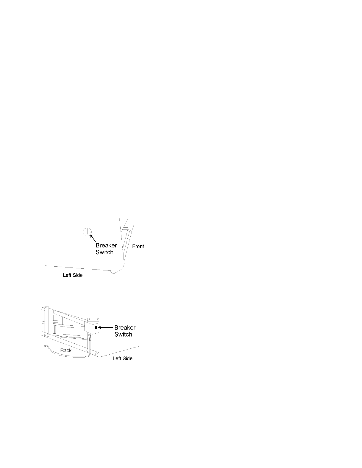
1. This unit is equipped with a circuit breaker on the side
or back. Turn this switch ON before starting this unit.
See illustrations below for breaker switch location.
2. Connect to a dedicated power source.
Note: When the unit is plugged in and the power switch turned
on, the audible alarm may sound. To temporarily silence the
alarm, open the control panel door and press the BZ button.
3. The factory setpoint for chamber temperature is 5°C.
Allow the unit to cool down to setpoint. The chamber
temperature is displayed on the temperature indicator
display on the control panel.
Note: Although the refrigerator will operate at under 2°C, it is
not suitable for prolonged use at this range. Always set the ther-
mostat above +2°C. When running the unit at the top of the
range (+14°C), the audible alarm may sound. In this case, it
does not indicate a malfunction. Press BZ on the control panel
to silence the alarm.
4. Turn the light switch to ON to verify its operation, then
turn it off for normal operation.
5. Make sure that the unit functions properly before plac-
ing product in the chamber. Add product to the chamber
gradually to prevent excessive temperature rise and sub-
sequent activation of the alarm system. Allow enough
space between the items to permit adequate air circula-
tion.
Model 3680 Series __________________________________________________________________Installation and Start-Up
1 - 2
Model 3684, 3686 and 3687
Model 3684, 3686 and 3687
Section 2 - Control Panel Procedures
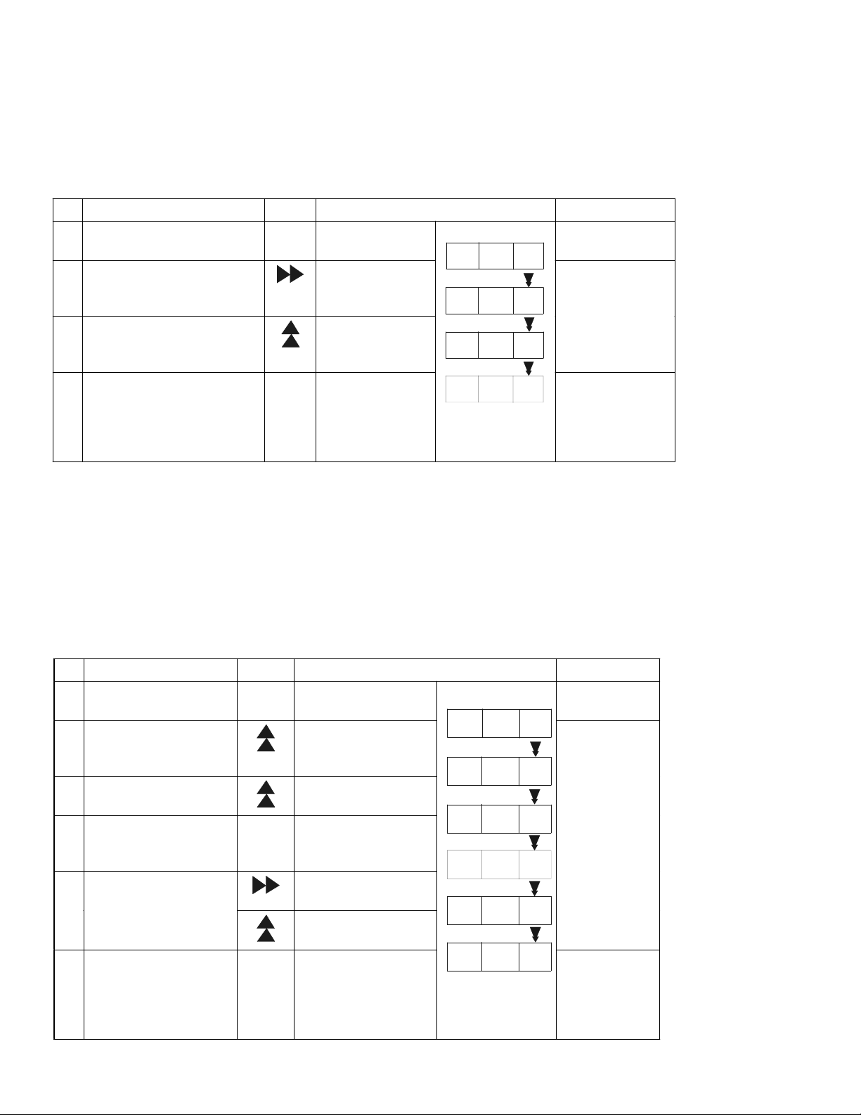
2.1 Temperature Control
The table below shows basic operation procedures for the
keys indicated. Follow the sequence as shown.
The temperature setpoint range is between 2° and 14°C.
Factory setpoint is 5°C. A partial freeze may be possible when
the temperature is set lower than 3°C.
If no keys are pressed for 90 seconds in temperature set-up
mode, the display returns automatically to current chamber tem-
perature display. The chamber temperature setpoint does not
change.
Model 3680 Series __________________________________________________________________Control Panel Procedures
2 - 1
Operation Key Display Mode
1 Connect to power source
and turn on power switch
---- Current chamber
temperature
Temperature
Display
2 Press the SET key SET First digit of
temperature flashes
Chooses the next
digit to be changed
3 Using the shift keys to
change the temperature
setpoint Increases the value
of the flashing digit
Temperature
Set-up
4 Press the SET key SET The value is stored
in memory and the
display returns to
the current chamber
temperature
TEMPERATURE (°C)TEMPERATURE (°C)
0 2 0
0 0 5
0 0 6
Temperature
Display
2.2 Key Lock Control
The key lock feature on this unit is to prevent unwanted
temperature setpoint changes. This feature is factory set to OFF.
To enter key lock mode, follow the sequence shown below.
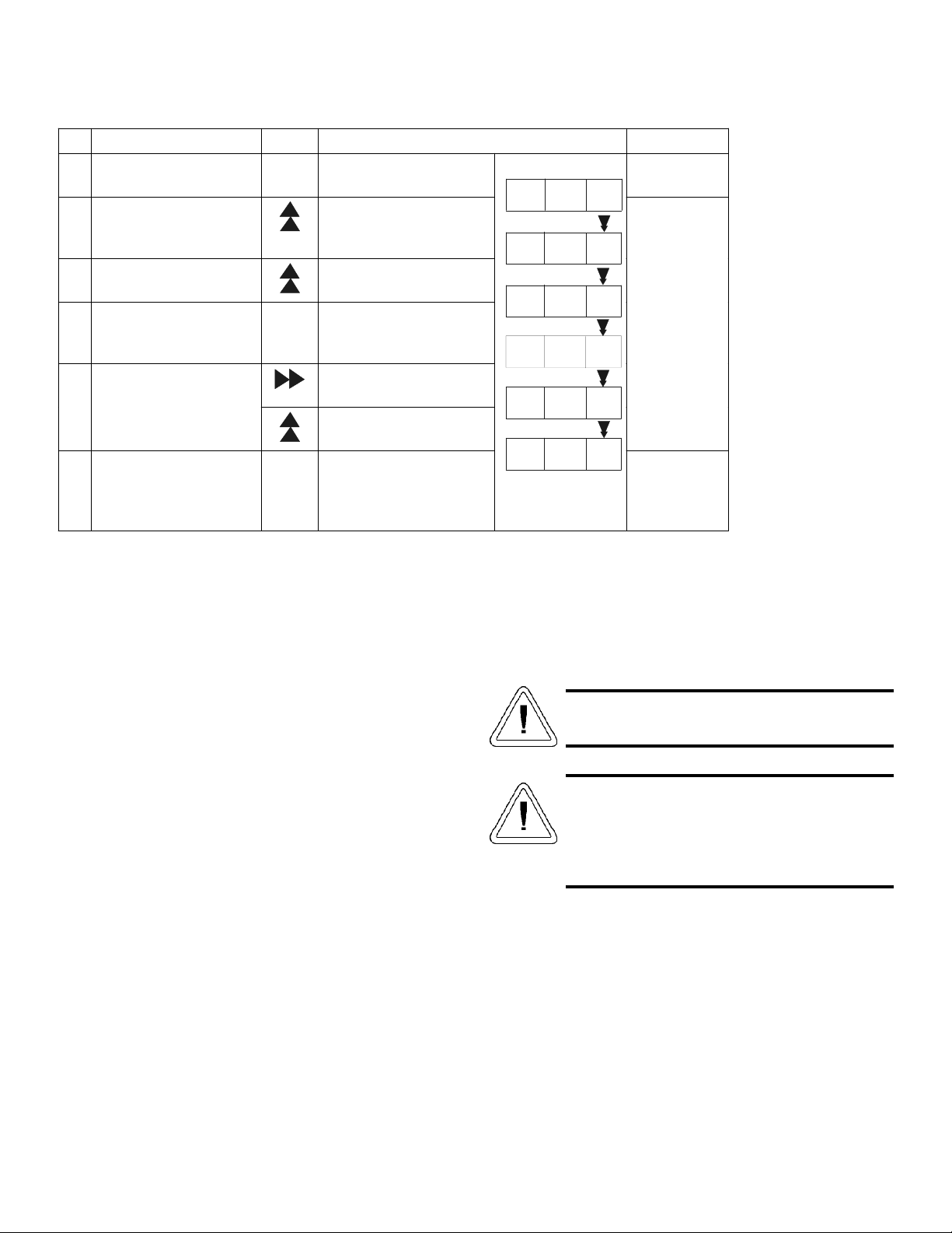
2.3 High and Low Temperature Alarm
The temperature alarm set range is between +2° and
+14°C. The factory setting is +5°C.
a. High Temperature Setpoint
For example, if the high temperature alarm setpoint
required is 3°C greater than the chamber temperature or you
wish the alarm to go off when the chamber temperature is 3°C
greater than the temperature setpoint, set the first digit (step 5)
to “3”.
Depending on the setting of the high temperature alarm set-
ting, when a large amount of product is placed into the cham-
ber, the alarm system may activate. After the chamber tempera-
ture reaches its setpoint, the alarm is automatically cancelled.
Model 3680 Series __________________________________________________________________Control Panel Procedures
2 - 2
Operation Key Display Mode
1 ---- Current chamber
temperature
Temperature
Display
2
Press and hold for 5 seconds
The first digit of
the temperature
display flashes
3 Set flashing digit to “1” Increases the
value of the
flashing digit
Key Lock
LO is enabled
(key lock off)
L1 is disabled
(key lock on)
4 Press the SET key SET Key lock is ON
and the display
returns to the
current chamber
temperature
TEMPERATURE (°C)TEMPERATURE (°C)
4
L 0
L 1
4
Temperature
Display
Operation Key Display Mode
1 ---- Current chamber
temperature
Temperature
Display
2 Press for 5 seconds The first digit on the
temperature display
flashes
3 Set the first digit to “1” Increases the value of
the flashing digit
4 Press the SET key SET The first digit of the
temperature display
flashes
Chooses the next
digit to be changed
5 Set the temperature
difference required for
alarm setpoint Increases the value of
the flashing digit
High
Temperature
Alarm Set
6 Press the SET key SET The value is stored in
memory and the
display returns to the
current chamber
temperature
TEMPERATURE (°C)TEMPERATURE (°C)
0 0 4
F 0 0
F 0 1
0 0 5
0 0 3
0 0 4
Temperature
Display
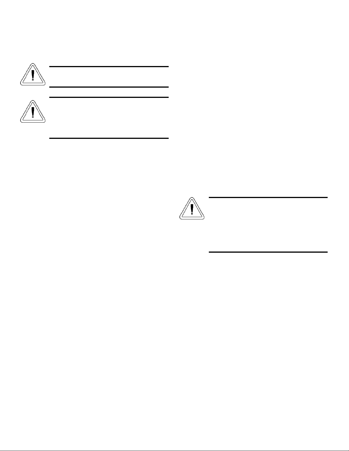
b. Low Temperature Setpoint
For example, if the low temperature alarm setpoint
required is 3°C less than the chamber temperature, or you wish
the alarm to go off when the chamber temperature is 3°C under
the temperature setpoint, set the first digit (step 5) to “3”.
Regardless of the low temperature alarm setting, if the
chamber temperature falls below 0°C, the alarm system will
activate to prevent freezing.
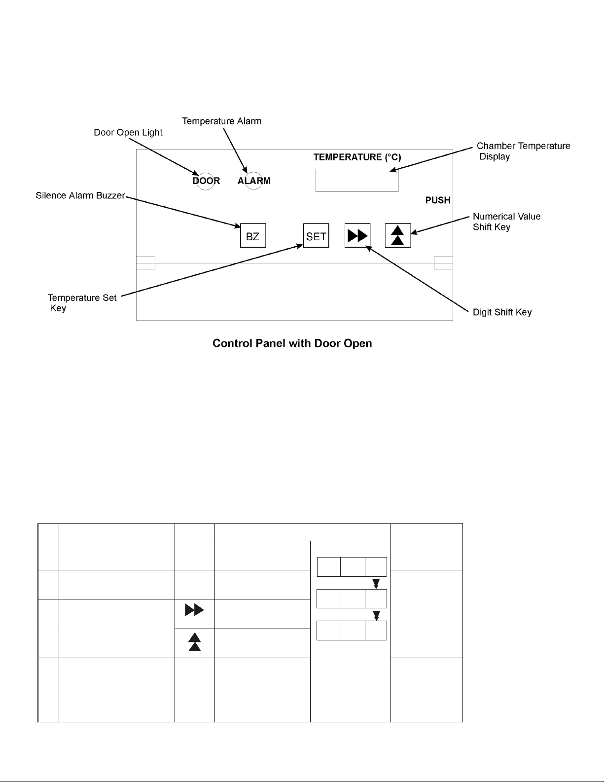
2.4 Door Open Light
When the door is opened, the DOOR indicator lights. This
light goes out automatically when the door is closed.
The alarm will activate if the door is open longer than 2
minutes. Press BZ to temporarily silence this alarm or it will
automatically deactivate when the door is closed.
2.5 Audible Alarm Switch
The audible alarm sounds when the chamber temperature
is above the high alarm setpoint for 15 minutes, when the
chamber temperature is below the low alarm setpoint for 15
minutes, or if the door remains open for 2 minutes.
Note: To silence the alarm, press BZ on the control panel.
2.6 Interior Lights Switch
The LIGHTS switch controls power to the lights inside the
chamber. Note: The light should be off during normal refriger-
ator operation and turned on when viewing the inside of the
chamber.
Model 3680 Series __________________________________________________________________Control Panel Procedures
2.7 Digital Temperature Display
TEMPERATURE display shows chamber temperature.
2.8 Remote Alarm Terminal
Disconnect the unit from power before beginning
any installation or service procedure.
Do not turn the refrigerator ON within 5 minutes
of turning it off. The compressor may not operate
properly without this 5 minute interval. This also
protects the compressor from excessive pressure
build-up.
The remote alarm terminal is located in the box on the
back of the cabinet. The normally-open contact capacity is
30VDC, 2A.
Note: The alarm buzzer stop key (BZ) silences the remote
alarm as well as the alarm buzzer, except when the power sup-
ply plug has been disconnected from the unit.
1. Remove the cover from the terminal box on the back of
the cabinet.
2. Connect the lead wire of the remote alarm equipment to
the terminal.
3. Reinstall the cover.
Operation Key Display Mode
1 ---- Current chamber
temperature
Temperature
Display
2 Press for 5 seconds The first digit on the
temperature display
flashes
3 Set the first digit to “2” Increases the value of
the flashing digit
4 Press the SET key SET The first digit of the
temperature display
flashes
Chooses the next digit
to be changed
5 Set the temperature
difference required for
alarm setpoint Increases the value of
the flashing digit
Low
Temperature
Alarm Set
6 Press the SET key SET The value is stored in
memory and the display
returns to the current
chamber temperature
TEMPERATURE (°C)TEMPERATURE (°C)
0 0 4
F 0 0
F 0 2
0 0 5
0 0 3
0 0 4
Temperature
Display
2 - 3

3 - 1
Section 3 - Maintenance
Disconnect the unit from power before beginning
any installation or service procedure.
Do not turn the refrigerator ON within 5 minutes
of turning it off. The compressor may not operate
properly without this 5 minute interval. This also
protects the compressor from excessive pressure
build-up.
3.1 Defrosting the Unit
a. Cycle Defrost
The defrost heater cycles automatically to clear any frost
accumulation on the refrigeration coils. This has no effect on
the chamber temperature.
b. Forced Defrost
If the ambient humidity is high or a large amount of damp
product is being stored in the chamber, the cycle defrost may
not be sufficient to remove all the frost from the refrigeration
coils and an automatic defrost function is initiated. This func-
tion is activated by a sensor located on the evaporator. When
this defrost function occurs, the current chamber temperature
and “dF” flashes alternately on the TEMPERATURE display.
The compressor will stop and a heater will be activated. When
the cycle is complete, normal operation resumes. The chamber
temperature may rise as much as 10° during this defrost cycle.
3.2 Cleaning Evaporation Tray and Condenser Filter
(Condenser, if applicable)
Clean the drain evaporation tray and condenser filter (con-
denser, if applicable) once a month.
a. Cleaning the Evaporation Tray
1. Remove the two screws securing the bottom front unit
cover.
2. Clean the cover.
3. Remove and empty the evaporation tray.
4. Clean the tray using a mild detergent and warm water.
Do not use hot or boiling water. Rinse the tray thorough-
ly and return it to the unit. Install the cover.
b. Cleaning the Condenser (3684, 3686)
Clean the condenser using a vacuum sweeper.
c. Cleaning the Condenser Filter (3688)
To prevent dust from clogging the condenser, a filter is
installed to the right of the evaporation tray.
1. Remove the bottom front cover, then hold the filter by
the leading edge and slide it to the left. Clean with
water, dry completely and return it to its original posi-
tion.
2. After cleaning both the evaporation tray and the con-
denser filter, secure the bottom front cover by aligning
the three pins at the top of the cover and installing the
two screws at the bottom.
3.3 Cleaning the Unit
Never splash or drip water on the outside of the
unit, as water can cause malfunctioning of the
electronic components.
Do not clean the unit with brushes, acid, benzene,
thinner, powdered soap, cleanser or hot water.
These agents can damage the cabinet’s finish and
any plastic or rubber components.
A dry cloth can be used to clean all areas of the unit
including the shelves and drawers. Any condensation that
forms on the front glass or frame may be wiped away.
Be sure to rinse completely with a clean cloth and water, if
using a mild detergent.
3.4 Replacing the Fluorescent Light
To replace the fluorescent light bulb, follow the procedure
below.
1. Turn the control panel light switch and power switch off.
Unplug the unit.
2. Remove all shelves from the left side of the chamber.
3. Grasp the light bulb assembly and pull it from the hold-
ing brackets.
4. Roll off the rubber connector protectors from each end
of the bulb.
5. Gently remove the bulb from the cover.
6. After placing the new bulb into the cover, reinstall the
rubber protectors.
7. Return the fluorescent light bulb assembly to its original
position.
Model 3680 Series ____________________________________________________________________________Maintenance

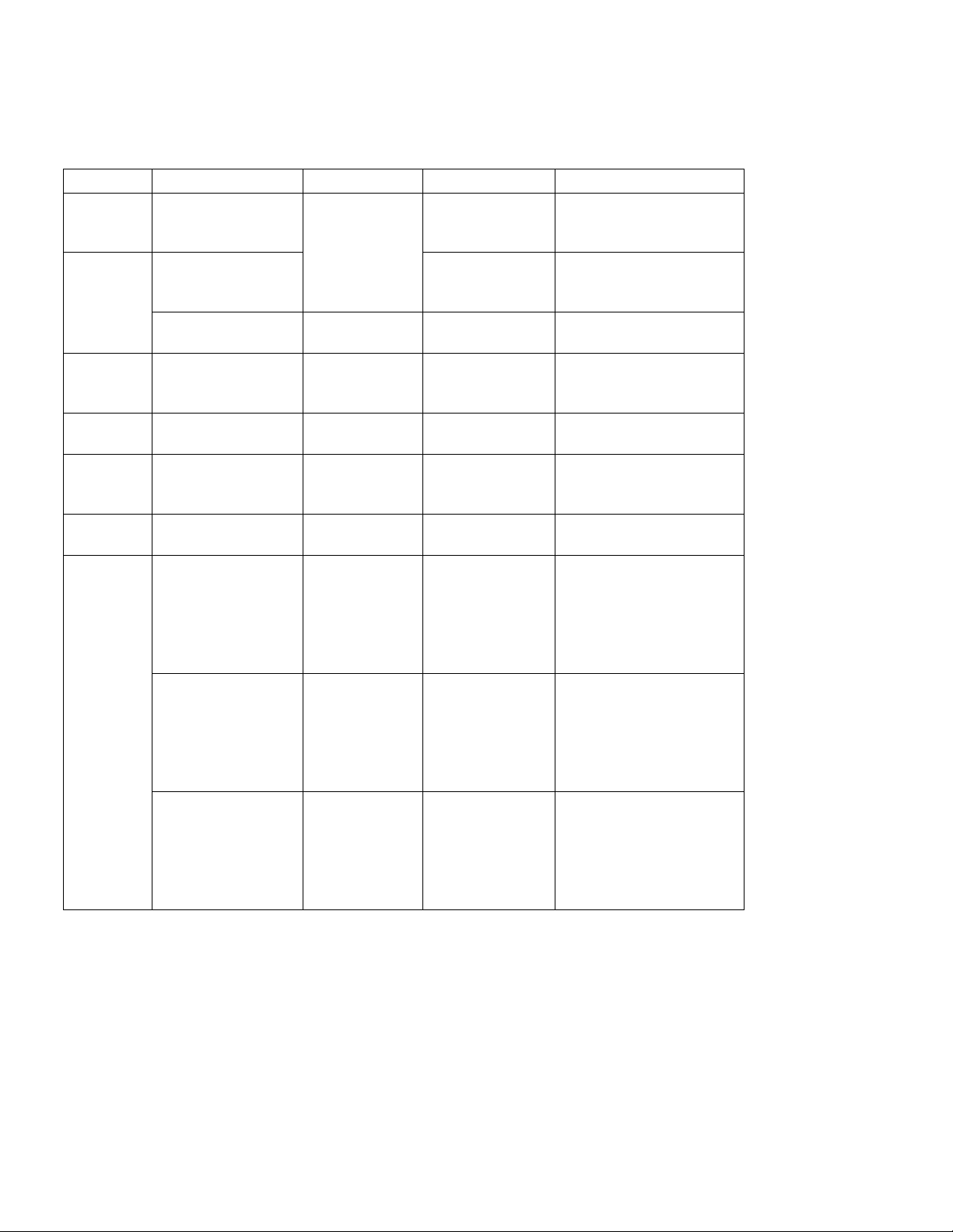
Section 4 – Troubleshooting
Note: When 2 or more alarm conditions occur simultaneously,
the lowest number code has priority on the display.
After a power failure, the unit will resume operation with
the set values that were in place before the power failure
occurred.
Model 3680 Series _______________________________________________________________________Troubleshooting
4 - 1
Type Symptom Indication Alarm Buzzer Safety Response
High
Temp
Alarm
Chamber temp
deviates from 2°C to
14°C above setpoint
Intermittent after
15 minute delay
Remote alarm is activated
after 15 minute delay
Chamber temp
deviates from 2°C to
14°C below setpoint
Alarm light
flashes
Temp display
flashes Intermittent Remote alarm is activated
after 15 minute delay
Low Temp
Alarm
If chamber temp is
lower than 0°C
--- --- Remote alarm is activated
Power
Failure
Alarm
Power failure or
accidental power
disconnect
--- --- Remote alarm is activated
Door
Alarm
Door is open DOOR light on Intermittent after
2 minute delay
---
Auto
Return
No keys pressed for
90 seconds in set
mode
Chamber temp
displayed
--- Set mode is cancelled
Key lock Key lock is on or set
to “1”
--- --- Key input is disabled
Temp sensor short
circuits
Alarm flashes
E1 and
chamber temp
flash
alternately on
display
Intermittent Remote alarm is activated
Defrost sensor operates
Defrost sensor short
circuits
Alarm flashes
E2 and
chamber temp
flash
alternately on
display
Intermittent tone Remote alarm is activated
Continuous running
Temp
Sensor
Problem
Defrost sensor 2
short circuits
Alarm flashes
E3 and
chamber temp
flash
alternately on
display
Intermittent Remote alarm is activated
Continuous running

Model 3680 Series _______________________________________________________________________Troubleshooting
4 - 2
4.1 Discarding or Taking the Refrigerator out of
Service
Federal regulations require that doors be removed
before being taken out of service or discarded.
Problem Possible Cause
Nothing operates even when turned on
•
Check electrical power
•
Electric power has failed or been
disconnected
Key Operation Unavailable •Is Key Lock set to OFF?
Poor Refrigeration
•
Temperature control not properly set
•
Too many warm items in the chamber
•
Frost on the evaporator
•
Freezer door opened and closed
frequently, or not closed tightly
•
Back of the refrigerator touching the wall
•Air exhaust vent blocked
•Unit in direct sunlight or too close to a
heat source
Alarm System Activated
•
Door not closed tightly
•
Too many warm items in the chamber
•Temperature setting changed

Section 5 – Specifications
Model 3684
Operating Temperature
+2°C (+35.6°F) to +14°C (+57.2°F)
Temperature Control
Electronic control with digital
temperature readout, readable to the
nearest °C.
Defrost Heater 148W
Fan Motor Chamber – output 3W (1)
Compressor 0.3 HP hermetically sealed
Refrigeration Forced cool air circulation
Refrigerant 5.6 oz. (158.8 grams) R134A
0.3 oz. (9.9 grams) N-Pentane
Capacity 17.3 cu. ft. (489 liters)
Interior Dimensions
31.44”W x 51.19”H x 18.31” F-B
(79.86cm x 130.02cm x 46.51cm)
Exterior Dimensions
35.44”W x 70.5”H x 23.63” F-B
(90.02cm x 179.07cm x 60.02cm)
Interior Light One 20W fluorescent light with
control panel-mounted switch
Insulation
Non-CFC foamed-in-place rigid
polyurethane
Shelving
Five adjustable shelves - 110.2 lbs.
(50 kg)/shelf load limit
Electrical 115 VAC, 1 PH, 60 Hz, 2.1 FLA
Weight 304.24 lbs (138 kg)
Model 3686
Operating Temperature
+2°C (+35.6°F) to +14°C (+57.2°F)
Temperature Control
Electronic control with digital
temperature readout, readable to the
nearest °C.
Defrost Heater 148W
Fan Motor Chamber – output 3W (1)
Compressor 0.3 HP hermetically sealed
Refrigeration Forced cool air circulation
Refrigerant 5.6 oz. (158.8 grams) R134A
0.3 oz. (9.9 grams) N-Pentane
Capacity 17.2 cu. ft. (486 liters)
Interior Dimensions
31.44”W x 51.19”H x 18.31” F-B
(79.86cm x 130.02cm x 46.51cm)
Exterior Dimensions
35.44”W x 70.50”H x 23.63” F-B
(90.02cm x 179.07cm x 60.02cm)
Interior Light One 20W fluorescent light with
control panel-mounted switch
Insulation Non-CFC foamed-in-place rigid
polyurethane
Shelving Five adjustable shelves – 44.0 lbs.
(20kg)/shelf load limit
Roll-out baskets 44.0 lbs. (20kg)/drawer load limit
Electrical 115 VAC, 1 PH, 60 Hz, 2.1 FLA
Weight 317.47 lbs (144kg)
Model 3680 Series ___________________________________________________________________________Specifications
5 - 1

Model 3688
Operating Temperature
+2°C (+35.6°F) to +14°C (+57.2°F)
Temperature Control
Electronic control with digital
temperature readout, readable to the
nearest °C.
Defrost Heater 175W
Fan Motor Chamber – output 9W (2)
Condenser – output 4W (1)
Compressor 0.4 HP hermetically sealed
Refrigeration Forced cool air circulation
Refrigerant 10.9 oz. (309 grams) R134A
0.7 oz. (20.1 grams) N-Pentane
Capacity 36.5 cu. ft. (1034 liters)
Interior Dimensions 66.88”W x 51.19”H x 18.31” F-B
(169.88cm x 130.02cm x 46.51cm)
Exterior Dimensions 70.88”W x 70.5”H x 23.63” F-B
(180.04cm x 179.07cm x 60.02cm)
Interior Light One 40W fluorescent light with
control panel-mounted switch
Insulation Non-CFC foamed-in-place rigid
polyurethane
Shelving Five adjustable shelves - 110.2 lbs.
(50kg)/shelf load limit
Ten roll-out baskets 44.0 lbs. (20kg)/drawer load limit
Electrical 115 VAC, 1 PH, 60 Hz, 3.1 FLA
Weight 562.18 lbs (255 kg)
Model 3680 Series ___________________________________________________________________________Specifications
5 - 2

Section 6 - Parts List
3684/3686 3688 Description
Stock # Stock #
227831 227929 Compressor
227774 227774 Starting Relay
227835 227775 Overload Relay
227936 227936 Overtemp Relay
227930 227930 Starting Capacitor
227931 227931 Running Capacitor
227933 227933 Undertemp Thermostat
227934 227925 Thermal Protector
N/A 227941 Condensing Fan Motor
227939 227939 Cooling Fan Motor, Right (3688)
N/A 227940 Cooling Fan Motor, Left (3688)
227942 227942 Thermal Fuse
227943 227944 Ballast
227945 227945 Lamp Switch
227946 227946 Door Switch
227935 227935 Power Relay
227938 227938 Power Supply
227871 227870 Main Power Switch/Circuit Breaker
227947 227190 Fluorescent Lamp Starter
227949 227950 Drain Pan Heater
227951 227952 Temp Control/Display Board
227953 227954 Temp Sensor
227937 227937 Defrost Sensor (black leads)
N/A 227960 Defrost Sensor (white leads)
Consult Consult Fluorescent Lamp 40W (3688)
Factory Factory Fluorescent Lamp 20W (3684/3686)
227948 Consult
Factory Defrost Heater
227989 227990 Display Board
Model 3680 Series _____________________________________________________________________________Parts List
6 - 1
This manual suits for next models
2
Table of contents


