Page 2of 18
TABLE of CONTENTS
SERIAL NUMBER INFORMATION.............................................................................................................................................3
APPLIANCE SAFETY...................................................................................................................................................................4
IMPORTANT SAFEGUARDS .......................................................................................................................................................4
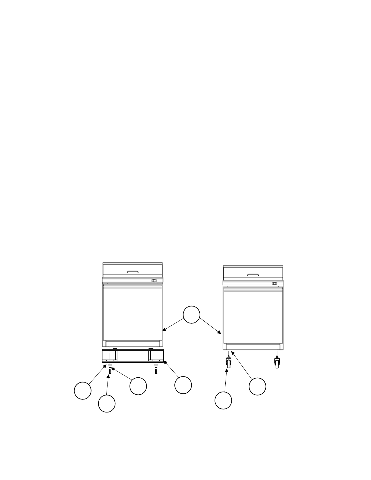
CASTER INSTALLATION
......................................................................................................................................................6
DIMENSIONS ................................................................................................................................................................................7
TECHNICAL INFORMATION......................................................................................................................................................7
RECEIVING AND INSPECTING THE EQUIPMENT.................................................................................................................8
INTRODUCTION
.........................................................................................................................................................................8
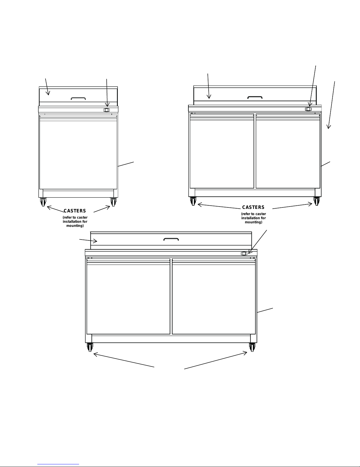
COMPONENT INFORMATION
.................................................................................................................................................9
APPLIANCE INSTALLATION....................................................................................................................................................10
Remove Packaging Materials....................................................................................................................................................10
Location Requirements..............................................................................................................................................................10
Inside cabinet:............................................................................................................................................................................10
Outside cabinet:.........................................................................................................................................................................10
Installation Clearance................................................................................................................................................................11
Stabilizing..................................................................................................................................................................................11
Electrical Connection ................................................................................................................................................................11
OPERATION.................................................................................................................................................................................12
Refrigerated cycle......................................................................................................................................................................12
Power Switch:............................................................................................................................................................................12
SOLID-STATE THERMOSTAT DESCRIPTIONS ......................................................................................................................12
1. FRONT PANEL COMMANDS ............................................................................................................................................12
2. MAIN FUNCTIONS.............................................................................................................................................................13
3. ALARM SIGNALLING........................................................................................................................................................13
CLEANING AND MAINTENANCE...........................................................................................................................................14
Exterior and Interior Cleaning of Appliances............................................................................................................................14
Cleaning the Condenser Coil.....................................................................................................................................................14
Stainless Steel Care and Cleaning.............................................................................................................................................15
Gasket Maintenance ..................................................................................................................................................................15
Doors/Hinges.............................................................................................................................................................................15
Drain Maintenance ....................................................................................................................................................................15
TROUBLESHOOTING GUIDE
................................................................................................................................................16
WIRING DIAGRAMS
................................................................................................................................................................17