Electronics Diversified Plus User manual

Plus
1
© 1997, 1998, Electronics Diversified, Inc.
070-0580
Revision 7, May 1998
Plus
Control Console
User Manual

Plus
2
INTRODUCTION
The Plus Console is designed to support a series of very basic
controlconceptsestablishedinthelightingindustry. Theseconcepts
are based on the fundamental idea of standard two-scene preset
operation with a healthy twist.
The layout of the Plus controls suggests a two-scene preset
background with two familiar rows of Channel sliders and a basic
set of Crossfaders. Each Channel and Submaster is equipped with
a Bump Button. Bump controls allow the operator to select the
feature and the level of the bump.
Plus also allows the operator to double the channel capacity with
the scene mode switch. When in 1 scene mode, the lower row of
sliders simply add to the upper row of sliders. This feature makes
it quick and easy to gain additional channel control when needed.
Plus incorporates the page concept for memory storage in both
Submaster and Preset memories. Each is equipped with a page
switch. This method layers the storage and allows the operator to
select a recorded memory from any page at any time. Pages can
be switched without affecting the current output.
Plus offers an Independent Fader with a pile-on or inhibit capacity.
This Fader can accept both preset memories and Submaster
memories in a manual or timed mode. When a memory is loaded
in either Fader 1 or 2, the Independent Fader, selected to Inhibit,
andthe channel slidercan subtract anychannels from therecorded
memory output. This unique feature allows fast edits and
adjustments based on live circumstances.
Plus also supports a monochromatic CRT, Off Line Printer, a Hand
Held Remote for dimmer address, Off Line Storage for up to 40
shows, Alphanumeric show labels, Preview capacities, and a
simple Effects package. All of these features are standard in an
economical control package.
So, as you step through this Guide, the real advantages will
become clear. For best results, work with the Guide and the Plus
together to highlight the features of the console.
We think the Plus is a step above the average preset control
console.
ABOUT THE PLUS CONSOLE
This Operational Guide is supplied with your system. Copies of this
guide may be obtained from Electronics Diversified, Inc. for a
nominal charge. It is recommended that you copy those portions
of this manual applicable to your present use in the installation,
maintenance or repair and preserve the original in a safe place.
© 1998, by Electronics Diversified, Inc. All rights reserved.
No part of this manual may be reproduced by any means, graphic,
electronic, or mechanical, including photocopying, recording,
taping, or information storage and retrieval systems, without the
express written permission of Electronics Diversified, Inc., except
inconnectionwithinstallation,repair and maintenanceofElectronics
Diversified, Inc. systems.

Plus
3
OVERVIEW
Front Panel . . . . . . . . . . . . . . . . . . . . . . . . . . . . . . . . . . .
4
Rear Panel . . . . . . . . . . . . . . . . . . . . . . . . . . . . . . . . . . .
4
Side Panel . . . . . . . . . . . . . . . . . . . . . . . . . . . . . . . . . . .
. 5
SET-UP
CRT Display. . . . . . . . . . . . . . . . . . . . . . . . . . . . . . . . . .
. 6
Keypad Display. . . . . . . . . . . . . . . . . . . . . . . . . . . . . . . .
6
CONTROLS
Keypad . . . . . . . . . . . . . . . . . . . . . . . . . . . . . . . . . . . . . .
. 8
Shifted Keys . . . . . . . . . . . . . . . . . . . . . . . . . . . . . . . . . .
9
Switches . . . . . . . . . . . . . . . . . . . . . . . . . . . . . . . . . . . . 10
Sliders . . . . . . . . . . . . . . . . . . . . . . . . . . . . . . . . . . . . . 11
Displays . . . . . . . . . . . . . . . . . . . . . . . . . . . . . . . . . . . . .
12
Effects . . . . . . . . . . . . . . . . . . . . . . . . . . . . . . . . . . . . . .
13
PATCH OPERATION
Access Patch . . . . . . . . . . . . . . . . . . . . . . . . . . . . . . . . .
14
Assign Patch . . . . . . . . . . . . . . . . . . . . . . . . . . . . . . . . . 14
THRU Function. . . . . . . . . . . . . . . . . . . . . . . . . . . . . . . .
14
AND Function. . . . . . . . . . . . . . . . . . . . . . . . . . . . . . . . .
15
Park Feature. . . . . . . . . . . . . . . . . . . . . . . . . . . . . . . . . 15
BUMP SET-UP
Configure . . . . . . . . . . . . . . . . . . . . . . . . . . . . . . . . . . . .
16
Playback. . . . . . . . . . . . . . . . . . . . . . . . . . . . . . . . . . . . .
16
PRESET OPERATION
Preparation . . . . . . . . . . . . . . . . . . . . . . . . . . . . . . . . . . 17
2-Scene Preset . . . . . . . . . . . . . . . . . . . . . . . . . . . . 18
TABLE OF CONTENTS
1-Scene Preset . . . . . . . . . . . . . . . . . . . . . . . . . . . . 20
4-Scene Preset . . . . . . . . . . . . . . . . . . . . . . . . . . . . 22
INDEPENDENT FADER
Pile-On Mode . . . . . . . . . . . . . . . . . . . . . . . . . . . . . . . . 24
Inhibit Mode . . . . . . . . . . . . . . . . . . . . . . . . . . . . . . . . . .
24
RECORDING A PRESET
Set Fade Time . . . . . . . . . . . . . . . . . . . . . . . . . . . . . . . 25
RECORDING A SUBMASTER
To Record . . . . . . . . . . . . . . . . . . . . . . . . . . . . . . . . . . . 26
FADER OPERATIONS
Loading a Preset . . . . . . . . . . . . . . . . . . . . . . . . . . . . . . 27
Loading a Submaster . . . . . . . . . . . . . . . . . . . . . . . . . . 27
Submaster Operation . . . . . . . . . . . . . . . . . . . . . . . . . . 28
EDITING
Edit a Preset . . . . . . . . . . . . . . . . . . . . . . . . . . . . . . . . . 29
Edit a Submaster . . . . . . . . . . . . . . . . . . . . . . . . . . . . . 31
EFFECTS OPERATION
Preparation . . . . . . . . . . . . . . . . . . . . . . . . . . . . . . . . . . .
.34
REMOTE RECORD
Plus to SubCommander. . . . . . . . . . . . . . . . . . . . . . . . . 35
OFF-LINE STORAGE
Save Show . . . . . . . . . . . . . . . . . . . . . . . . . . . . . . . . . . 36
Load show . . . . . . . . . . . . . . . . . . . . . . . . . . . . . . . . . . .
36
PRINTERS
Set-Up . . . . . . . . . . . . . . . . . . . . . . . . . . . . . . . . . . . . . .
37
CRT DISPLAYS
Set-Up Screen . . . . . . . . . . . . . . . . . . . . . . . . . . . . . . . .
38
Stage Screen . . . . . . . . . . . . . . . . . . . . . . . . . . . . . . . . 38
Patch Screen . . . . . . . . . . . . . . . . . . . . . . . . . . . . . . . . .
39
Preset Screen . . . . . . . . . . . . . . . . . . . . . . . . . . . . . . . . .
39
Submaster Screen . . . . . . . . . . . . . . . . . . . . . . . . . . . . 40
Save Screen . . . . . . . . . . . . . . . . . . . . . . . . . . . . . . . . . 40
Disk Screen . . . . . . . . . . . . . . . . . . . . . . . . . . . . . . . . . .
41
Help Screen . . . . . . . . . . . . . . . . . . . . . . . . . . . . . . . . . .
41
ADDENDUM
Plus
4
OVERVIEW
23579
10
8641
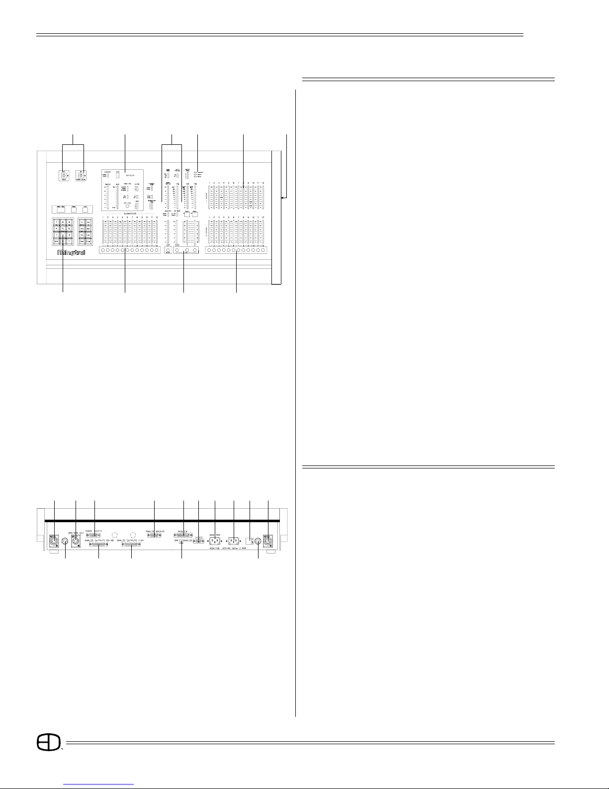
FRONT PANEL
1 2 3 5 6 1
8 9 10 11
44712
12
01. COMMAND KEYPAD:
Numeric Keypad and LED display with keys for access to Patch,
Channel, Level, Preset, Submaster and Disk functions.
02. KEY SWITCHES:
Key access to both power and record functions.
03. EFFECTS CONTROLS:
Program controls for Chase effects to include dedicated level and
rate controls.
04. SUBMASTERS:
Four pages of 12 overlapping submaster memories with bump
buttons and bank load capacities.
05. PLAYBACK CONTROLS:
Split dipless cross-faders with timer controls and LED preset displays.
An Independent fader for pile-on or inhibitive capacity. Bump mode
controls with off, level control, and solo selections. Grand Master
and blackout switch.
06. LOAD/RECORD KEYS:
When selected with preset key loads to a specified fader.
When selected with preset key records to a specified preset.
07. INDICATOR PACKAGE:
For Power, Back-Up and Overtemp conditions.
08. BUMP BUTTONS:
Channel bump buttons and/or preset record keys.
09. CHANNEL CONTROLS:
Single or two-scene channel controllers for individual level setting.
10. DISK DRIVE:
Multi-Show off-line storage of recorded information.
REAR PANEL
01. SCRIPT LIGHT RECEPTACLE:
For optional Console Script Lights.
02. DMX-AMX OUT:
Console output locking 5-pin XLR connector.
03. HOUSELIGHTS:
D15-pin connector for analog houselights.
04. ANALOG OUTPUT PORTS:
2 D25-pin connectors for 0-10 VDC output.
(1-48 channel capacity)
05. ANALOG BACK-UP:
For connection to EDI Multi-Link 10-channel backup. Function
switch must be selected.
06. PRINTER PORT:
D25-pin for connection to standard parallel printer.
(IBM-PC Parallel)
07. OUTPUT SELECTOR SWITCH:
Selects console output options: DMX-512; AMX-192; or Analog
back-up.
Plus

Plus
5
OVERVIEW
08. VIDEO OUTPUT:
D9-pin connector for standard monochromatic video output.
(TTL-Monochrome)
09. MONITOR POWER:
Grounded Edison connector for monitor: 100 Watts max.
10. CONSOLE POWER:
Grounded recessed Edison connector for console power, 3 Amps
max.
11. FUSE HOLDER:
3 Amp fuse holder. (Not user replaceable)
12. SCRIPT LIGHT DIMMER:
12-Volt, 200-300 mA, 2.4 Watt low-intensity lamp.
SIDE PANEL
DISK HANDLING PROCEDURE:
DISK DRIVE: 3.5" IBM format, 1.44MB. Disks must be formatted
by the Plus console before use.
Insert the diskette as illustrated. Do not force it into the drive. If the diskette
will not insert easily, it is not correctly oriented.
To eject the diskette, push the small button on the disk drive.
To protect your data:
Do not expose to high temperatures.
Do not store near magnetic fields.
Do not eject a diskette while the disk drive indicator light is on. This could
result in loss of data or incomplete loading of a show. Wait until the
indicator light goes off before ejecting.
TO FORMAT A DISK:
Disk must be formatted before recording show information to the disk.
Press and hold Shift and Press 5
Select 12; press Enter
When format is complete, disk will stop and console restores.
WRITE PROTECTION:
Write protection locks the disk, preventing alteration of stored data. To
write protect the disk:
Orient the diskette so that the round metal circle is pointed toward you.
With the metal flap on top, the write-protect tab is located in the lower
right-hand corner. If this tab is closed, the diskette is not Write Protected.
If the tab is open, the diskette is Write Protected, and no new data can
be recorded.
Diskettes may be purchased from EDl (Part#119-0058) or any
computer supply house. Diskettes should be double-sided,
high-density, MF2-HD diskette equivalent. Two non-formatted
disks are supplied with the Plus console.
Indicator Light Eject Button
3.5" Disk
Write-protect Tab
Disk Drive
Plus
6
05. SHOW VERSION:
Current software version installed is displayed.
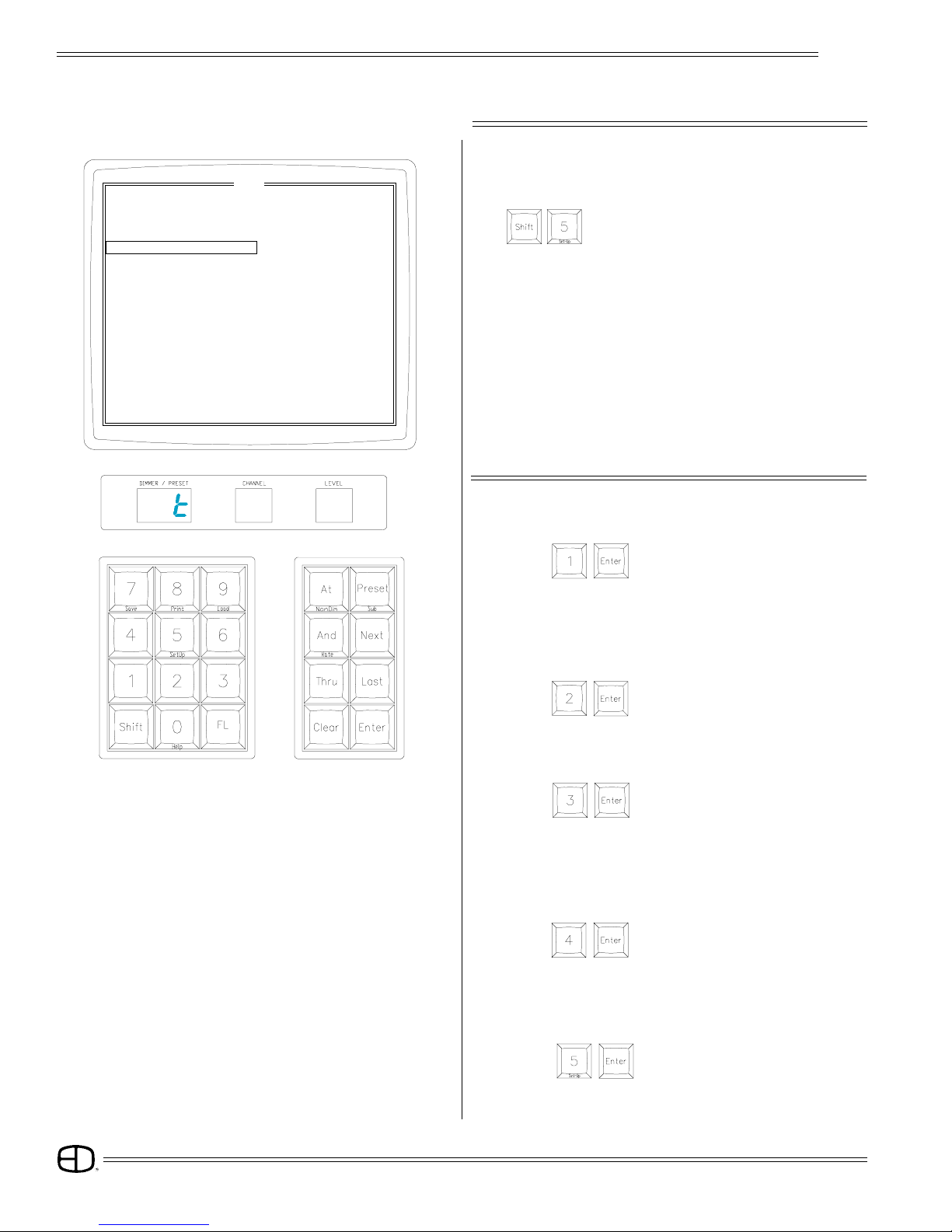
Select:
SET-UP
CRT DISPLAY
TO ACCESS SET-UP:
Hold (SHIFT) and press (5) (SETUP).
NOTE: Use NEXT, LAST keys to position highlight bar on CRT
or enter number and press ENTER.
On models without CRT, enter number on keypad. For
item to be selected, press ENTER to start.
1. Test Channels 2. Change Channel Count
3. Test Dimmers 4. Change Dimmer Count
5. Show Version 6. Clear Memory
7. Unity Patch 8. Modulus Patch
9. Auto Follow Wrapping 10. +Independent Not Assigned GM
11. Check Disk 12. Format Disk
13. Midi Address 14. Remote Store
[ SETUP ]
UP 01
SE
04. CHANGE DIMMER COUNT:
Select:
Current Dimmer count is displayed. Select new dimmer
count less than 512 and press ENTER. Patch operations
are limited to number selected.
1. TEST CHANNELS:
Select:
All Channels are set to the level of Fader 1 and individually set
to the level of Fader 2 at a rate determined by the Independent
Fader.
Press CLEAR to stop test.
KEYPAD DISPLAY
2. CHANGE CHANNEL COUNT:
Select:
Current channel count is displayed. Select new channel
count less than available channels and press ENTER.
3. TEST DIMMERS:
Select:
All Dimmers are set to the level of Fader 1, and individually set
to the level of Fader 2 at a rate determined by the Independent
Fader.
Press CLEAR to stop test.

Plus
7
SET-UP
06. CLEAR MEMORY:
Clears recorded Presets, Submasters and Faders.
Patch defaults to Unity Patch.
Select:
07. UNITY PATCH:
Select:
Installs one Dimmer per Channel patch for available channels.
08. MODULUS PATCH:
Select:
Installs wrap-around patch for Dimmers to Channels.
09. AUTO-FOLLOW WRAP:
Select:
Allows all four preset pages to Auto-follow into Crossfades by
loading the first preset of the next page after the last preset
of the current page is displayed.
Auto-follow stops at the last recorded preset on page 4.
10. INDEPENDENT FADER ASSIGN:
Assigns or releases Independent Fader to Grand Master
control.
Select:
UP 01
11. CHECK DISK:
Select:
Checks and confirms information stored on disk.
1. Test Channels 2. Change Channel Count
3. Test Dimmers 4. Change Dimmer Count
5. Show Version 6. Clear Memory
7. Unity Patch 8. Modulus Patch
9. Auto Follow Wrapping 10. +Independent Not Assigned GM
11. Check Disk 12. Format Disk
13. Midi Address 14. Remote Store
[ SETUP ]
SE
12. FORMAT DISK:
NOTE: Formatting erases all information on disk.
Select: (Required for new disk.)
13. MIDI ADDRESS:
Select:
Optional Midi protocol.
14. REMOTE STORE:
Select:
Assigns output to Page and Playback number on the
Subcommander. The user will be prompted for the
SubCommander page and playback, page in Channel
window, and playback in Level window.
Press CLEAR to stop any test.
Press CLEAR to quit Set-Up function.
Plus
8
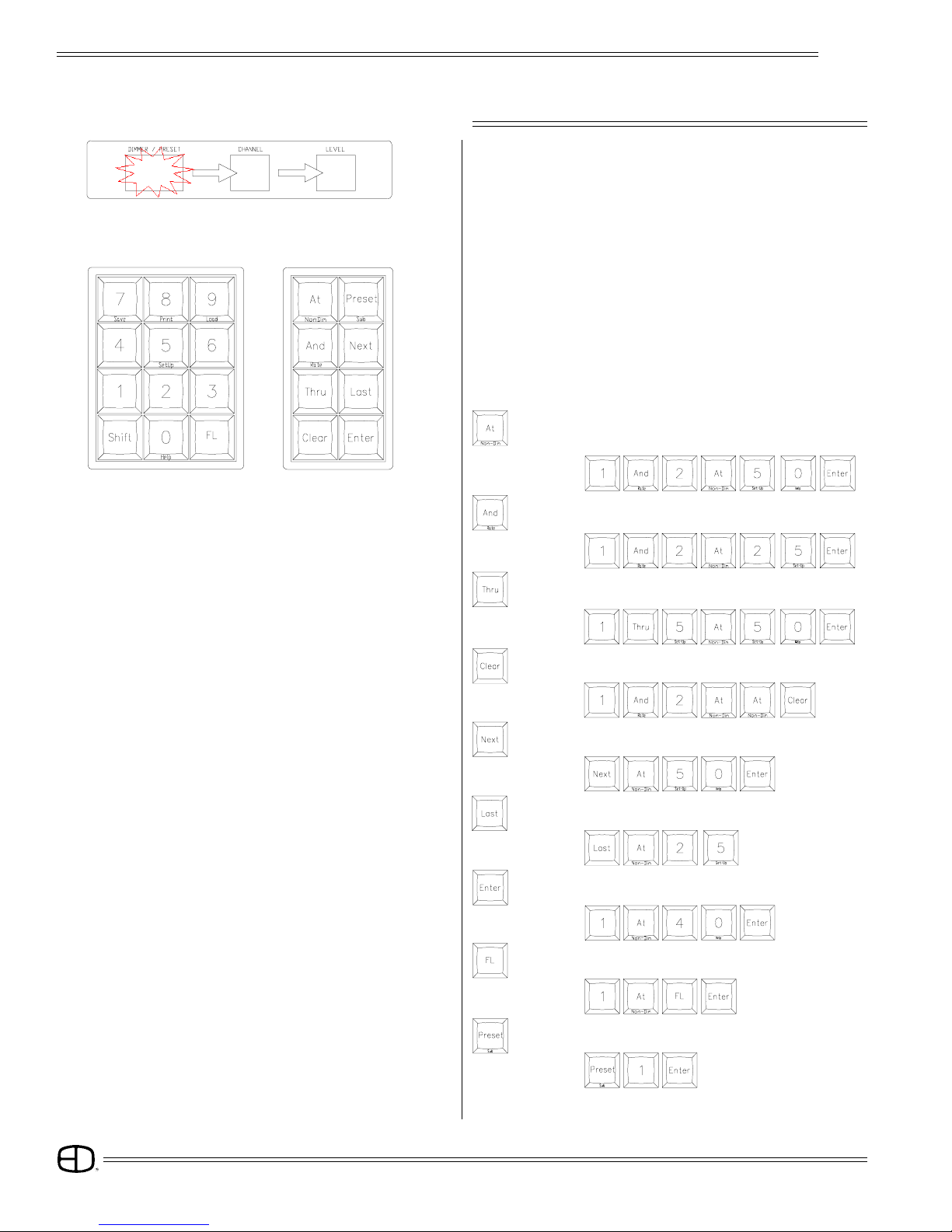
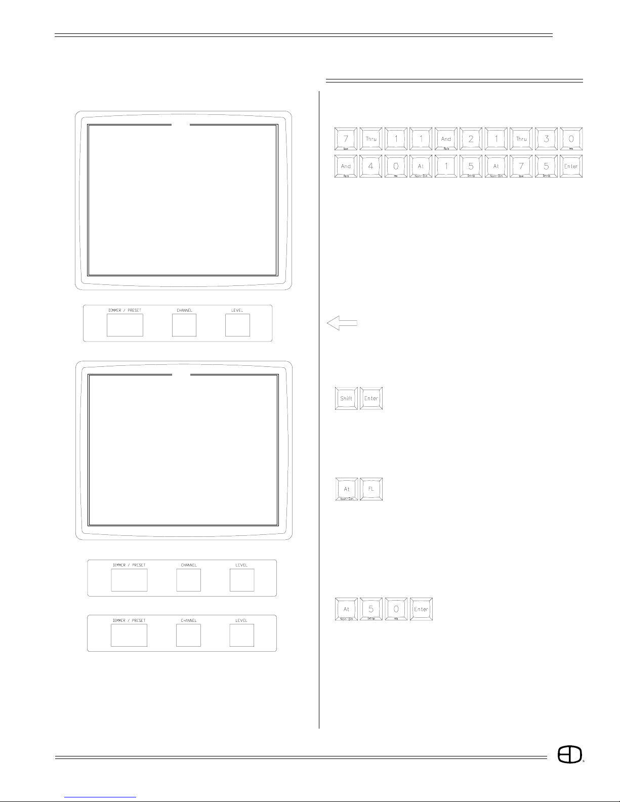
=THRU: Groups of Dimmers or Channels are selected.
= AND: Sets of Dimmers or Channels are selected.
EXAMPLE:
= CLEAR: Removes last entry.
Upon pressing ENTER, a window blinks, indicating where the
next data entry will go.
CLEAR removes data entry in the current window and moves to
the next window, left.
ENTERacceptsthedata in thecurrentwindowand moves tothe
next window, right.
AT defers acceptance of data in the current window and moves
to the next window, right.
= AT: Ends entry and moves active window to the
right.
EXAMPLE:
EXAMPLE:
KEYPAD
HINT: The keypad is the entrance to Blind/Edit functions.
This capacity allows access to memory functions
different from the Stage output. In the Blind Mode, edits
to levels may occur without affecting the existing stage
picture.
EXAMPLE:
CONTROLS
= LAST: Selects the previous number.
= NEXT: Selects the next number.
EXAMPLE:
EXAMPLE:
= ENTER: Accepts numbers and stores information.
EXAMPLE:
= FL: Assigns 100% value to entry.
= PRESET: Selects editing of recorded Presets.
EXAMPLE:
EXAMPLE:

Plus
9
CONTROLS
SHIFTED KEYS
Some keys have names on the front of the key. To access this
function, Press and Hold the SHIFT key and select the desired
function key.
= NON-DIM:
Sets a Dimmer to a Non-Dim when in the Patch
mode.
= RATE:
Selects fade rate assignment for Preset and
Submasters when in the Submaster or Preset
screen.
= SUB:
Selects editing of a recorded Submaster.
= SET-UP:
Accesses system Setup options.
= SAVE:
Records system memory to the disk.
= PRINT:
Prints selected information.
= LOAD:
Loads disk information into system memory.
= HELP:
Accesses system Help program.
= STAGE:
Accesses screen for direct channel output or
current output status.
= PATCH:
For assignment of dimmers to control channels at
levels.
Plus
10
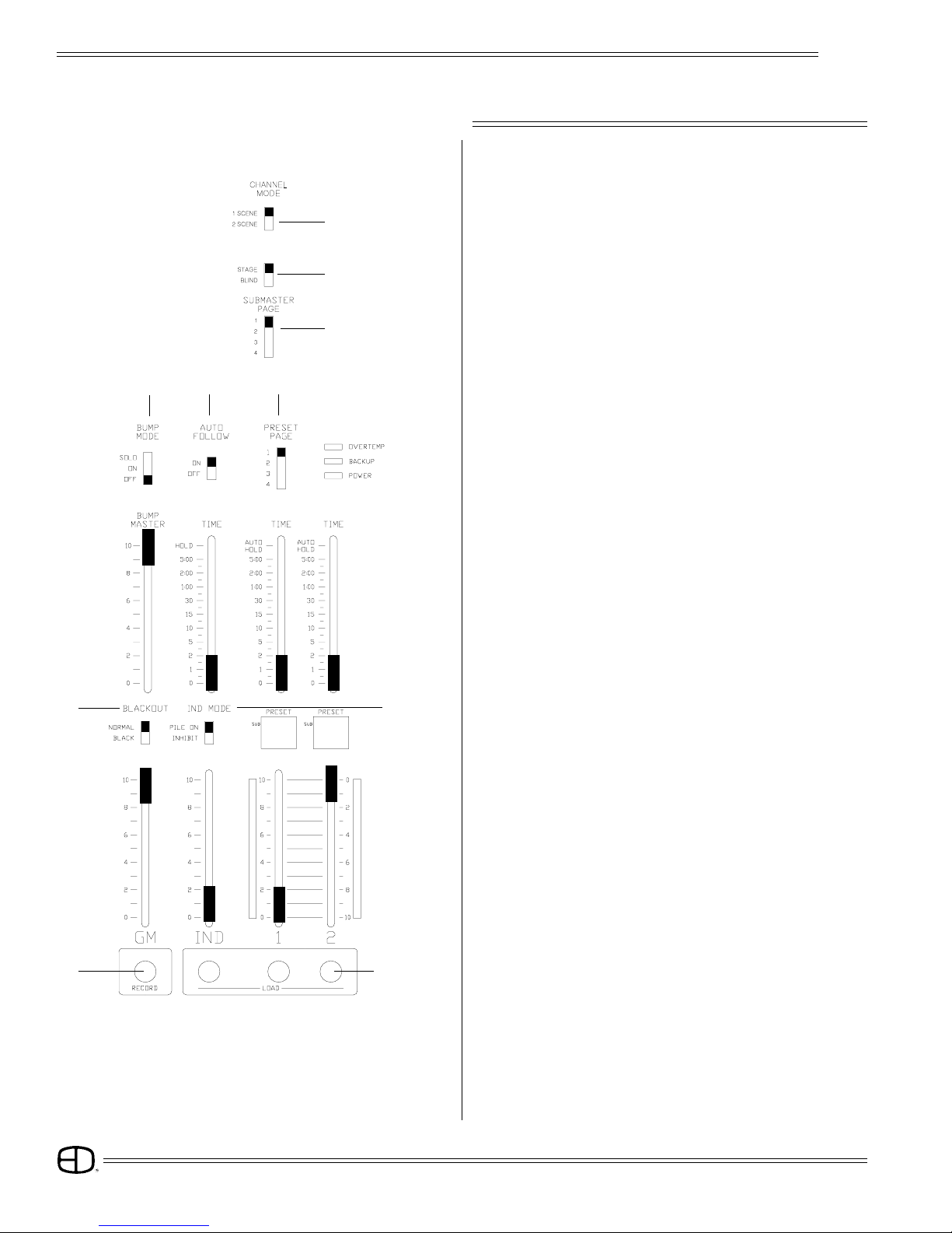
SWITCHES
CONTROLS
1. CHANNEL MODE:
Selects single or two-scene operation.
2. STAGE/BLIND:
Selects all outputs for Stage Record or only channel outputs
for Blind.
3. SUBMASTER PAGE:
Selects active Submaster memory, pages 1 through 4.
4. BUMP MODE:
Selects Bump button function:
SOLO,
ON, or
OFF.
5. AUTO FOLLOW:
Enables loading next sequential preset onto next fader
automatically.
6. PRESET PAGE:
Up to 4 Preset pages are available with the number of channel
bump buttons, equalling the number of memory spaces
available.
7. BLACKOUT:
In the Black position, all levels are forced to OFF immediately.
8. INDEPENDENT MODE:
Selects Pile-on or Inhibit mode for the Independent Fader.
9. RECORD:
Selects recording of active levels into Presets, Submasters or
Faders.
10. LOAD:
Selects Fader to be loaded.
5
46
8
10
1
2
3
7
9
Plus
11
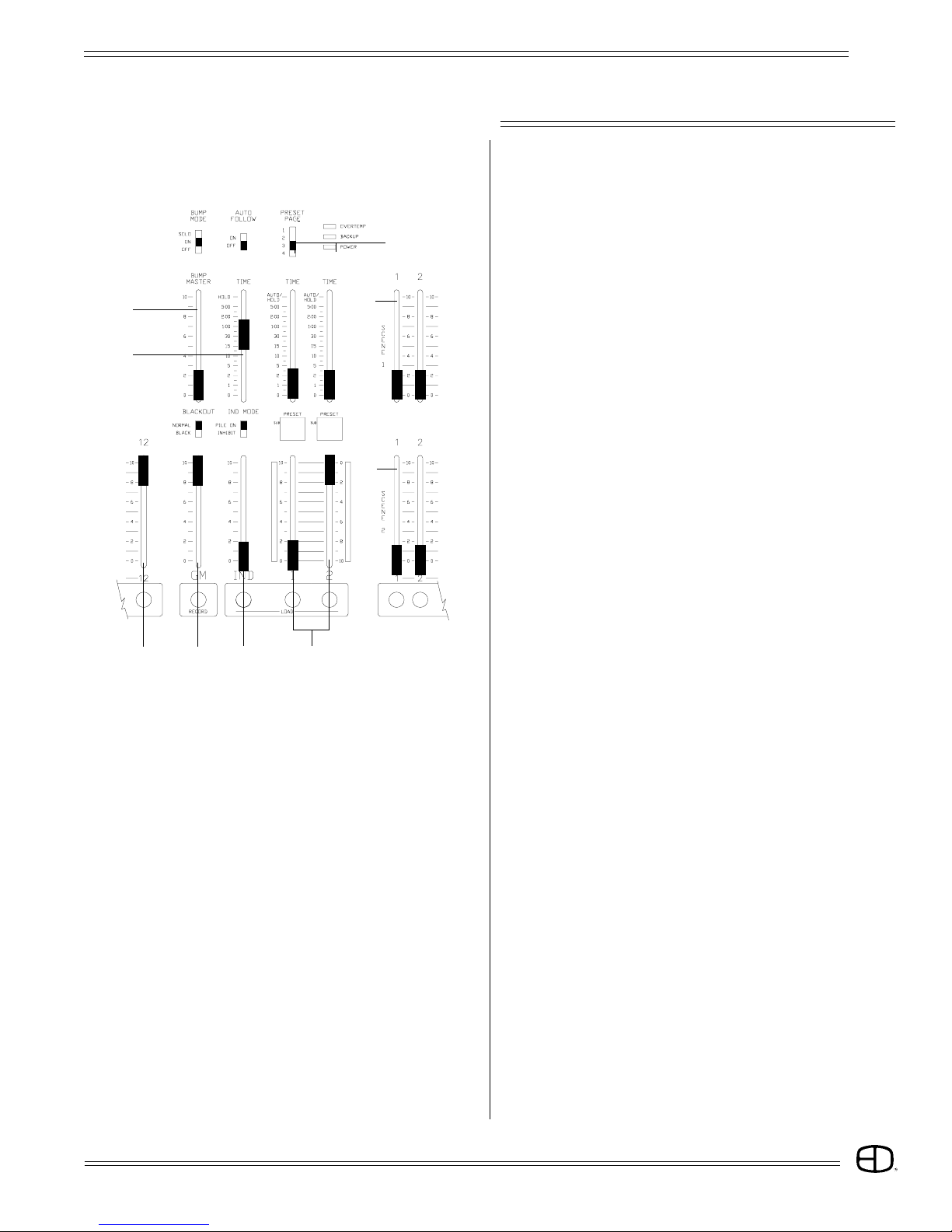
SLIDERS
1. BUMP MASTER:
Controls minimum output level for Bump functions.
2. INDEPENDENT FADE RATE TIMER:
Sets fade times for Independent Fader.
3. SUBMASTERS:
Twelve individual Pile-on memory faders.
4. GRAND MASTER:
Controls overall console output level.
5. INDEPENDENT FADER:
Third Playback Fader for Submaster and Preset memories,
or:
Manual control of Channels.
6. CROSSFADERS:
Produces split/dipless fades between two scenes.
7. CROSSFADER TIMERS:
Sets fade time for associated Faders;
or:
Auto setting for recorded time playback.
8. SCENE 1 SLIDERS:
Sets levels for Scene 1, used by Fader 1 in manual mode;
or:
Used as source for levels in BLIND mode.
9. SCENE 2 SLIDERS:
Sets levels for Scene 2, used by Fader 2 in manual mode;
or:
Used as source for additional levels in 1 Scene mode; also
a source for Blind in 1-Scene mode.
CONTROLS
2
1
345
7
9
8
6
Plus
12
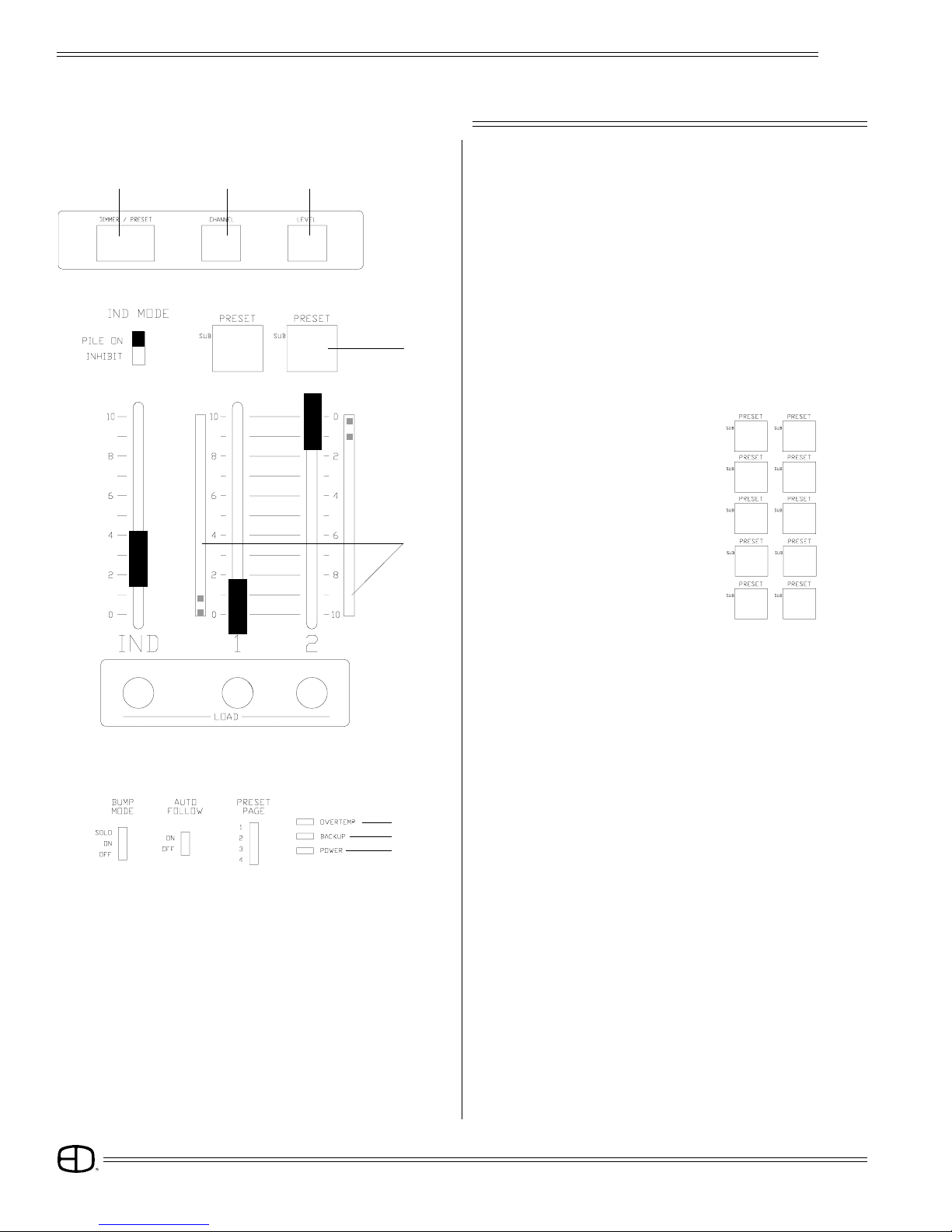
CONTROLS
4. FADER WINDOWS:
Display the Fader source.
5 Modes --Hold Status:
2-Scene Manual:
1-Scene Manual:
Preset:
Submaster:
5. BARGRAPHS:
Indicate active status of Crossfades.
1. DIMMER/PRESET WINDOW:
Displays the current dimmer, Preset or Submaster for Patch
and Edit functions.
2. CHANNEL WINDOW:
Displays the selected Channel for Patch and Edit functions.
3. LEVEL WINDOW:
Displays the selected Level for Patch and Edit functions.
123
P24 01 - -
DISPLAYS
(Blinking numbers means next entry in this window.
To advance active window, press ENTER or AT.
To access previous window, press CLEAR).
H1 H2
-1 -2
- -
- -
28
14
01
●●12
5
4
6. OVERTEMP:
Indicates a dimmer cabinet overtemp condition.
7. BACKUP:
Indicates when the console is in Backup mode.
8. POWER:
Indicates console ON.
7
6
8
Plus
13
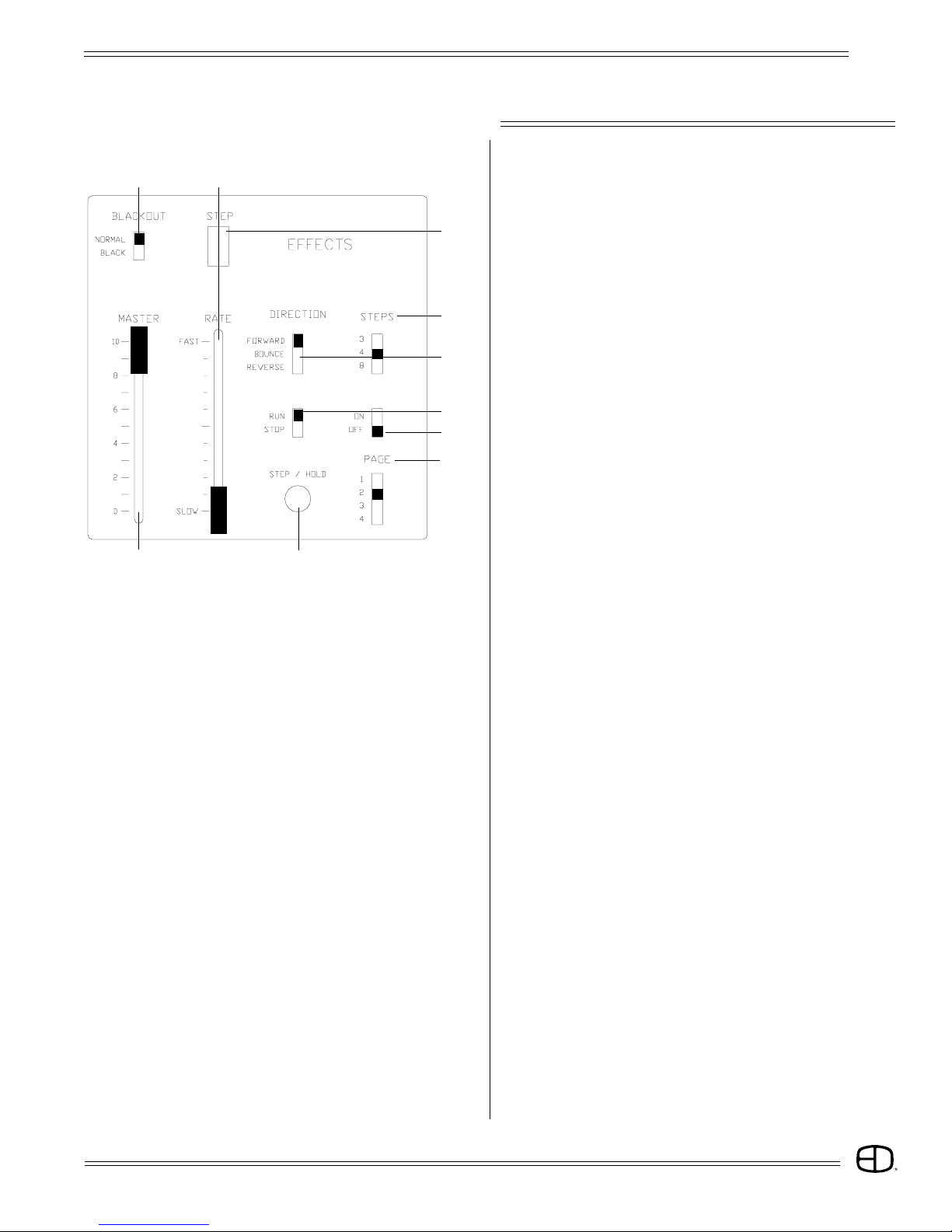
CONTROLS
EFFECTS
01. ON/OFF:
Turns Effects On and Off.
02. STEPS:
Determines the number of 'looks' in the Effect.
03. DIRECTION:
Determines the direction of the Effect.
04. STEP:
Indicates a 'look' currently active by the Effect generator.
05. RUN/STOP:
Runs or stops the Effect in progress.
06. STEP/HOLD:
Holds a running Effect, or steps a stopped Effect.
07. BLACKOUT:
Forces Effect levels to zero output.
08. RATE SLIDER:
Varies the speed of the Effect.
09. MASTER:
Varies the intensity of the Effect.
10. PAGE:
Selects Submaster memory page in which the Effect is
active.
3
6
10
5
2
4
78
9
1

Plus
14
TO ACCESS PATCH:
Press and hold (SHIFT), press (ENTER).
Displays Patch screen on CRT.
TO ASSIGN UNITY:
Shows SETUP Screen.
Installs one dimmer per channel patch for available
channels.
Shows SETUP Screen.
Installs wrap-around patch for dimmers to channels.
(Used for Test purposes only.)
TO ASSIGN MODULUS:
TO ASSIGN PATCH:
WhenDimmer/Presetwindowisblank, select DimmerorDimmers
to be assigned.
Press (AT) and select the channel to control the Dimmer(s).
Press (AT) and select the proportion of the channel level to be
output.
Press (ENTER).
(ENTER) advances the next number in the Dimmer/Preset
window. Repeat until all system Dimmers are assigned to the
available channels. Record Patch to disk (position #) for safety.
THRU FUNCTION:
The THRU key allows a continuous section of Dimmers to be
selected as a group for patch operations.
5 10 FL
2
- - -
3
- - -
- -
[ PATCH ]
DIM 123456789101112131415
CH 123456789101112131415
% FL FL FL FL FL FL FL FL FL FL FL FL FL FL FL
16 17 18 19 20 21 22 23 24 25 26 27 28 29 30
16 17 18 19 20 21 22 23 24 25 26 27 28 29 30
FL FL FL FL FL FL FL FL FL FL FL FL FL FL FL
46 47 48 49 50 51 52 53 54 55 56 57 58 59 60
46 47 48 49 50 51 52 53 54 55 56 57 58 59 60
FL FL FL FL FL FL FL FL FL FL FL FL FL FL FL
61 62 63 64 65 66 67 68 69 70 71 72 73 74 75
61 62 63 64 65 66 67 68 69 70 71 72 73 74 75
FL FL FL FL FL FL FL FL FL FL FL FL FL FL FL
31 32 33 34 35 36 37 38 39 40 41 42 43 44 45
31 32 33 34 35 36 37 38 39 40 41 42 43 44 45
FL FL FL FL FL FL FL FL FL FL FL FL FL FL FL
PATCH
OPERATION
2 5 FL
Plus
15
PATCH
OPERATION
AND FUNCTION:
The AND key allows Dimmers and groups of Dimmers to be
handled as a combined set for patch operations.
(ENTER) advances the next number in the Dimmer/Preset
window.
(Preset/Dimmer window will look like this after last entry).
PARK FEATURE:
Hold (SHIFT) and press (ENTER).
Patch Screen is displayed. Park feature assigns constant Dimmer
output regardless of fader positions.
Select Dimmer or Dimmers, press (AT) to change to Channel
window and press (FL) to select PARK.
Press (AT) to change to Level window and select output level
desired and press (ENTER). Dimmers will output at the
assigned level until reassigned.
40 15 7 5
[ PATCH ]
DIM 123456 78 9 101112 13 14 15
CH 12345615 15 15 15 15 12 13 14 15
% FLFLFLFLFL FL75 75 75 75 75 FL FL FL FL
16 17 18 19 20 21 22 23 24 25 26 27 28 29 30
16 17 18 19 20 15 15 15 15 15 15 15 15 15 15
FL FL FL FL FL 75 75 75 75 75 75 75 75 75 75
46 47 48 49 50 51 52 53 54 55 56 57 58 59 60
46 47 48 49 50 51 52 53 54 55 56 57 58 59 60
FL FL FL FL FL FL FL FL FL FL FL FL FL FL FL
61 62 63 64 65 66 67 68 69 70 71 72 73 74 75
61 62 63 64 65 66 67 68 69 70 71 72 73 74 75
FL FL FL FL FL FL FL FL FL FL FL FL FL FL FL
31 32 33 34 35 36 37 38 39 40 41 42 43 44 45
31 32 33 34 35 36 37 38 39 15 41 42 43 44 45
FL FL FL FL FL FL FL FL FL 75 FL FL FL FL FL
[ PATCH ]
DIM 123456789101112131415
CH 123456789101112131415
% FL FL FL FL FL FL FL FL FL FL FL FL FL FL FL
16 17 18 19 20 21 22 23 24 25 26 27 28 29 30
16 17 18 19 20 21 22 23 24 25 26 27 28 29 30
FL FL FL FL FL FL FL FL FL FL FL FL FL FL FL
46 47 48 49 50 51 52 53 54 55 56 57 58 59 60
46 47 48 49 50 51 52 53 54 55 56 57 58 59 60
FL FL FL FL FL FL FL FL FL FL FL FL FL FL FL
61 62 63 64 65 66 67 68 69 70 71 72 73 74 75
61 62 63 64 65 66 67 68 69 70 71 72 73 74 75
FL FL FL FL FL FL FL FL FL FL FL FL FL FL FL
31 32 33 34 35 36 37 38 39 40 41 42 43 44 45
31 32 33 34 35 36 37 38 39 40 41 42 43 44 45
FL FL FL FL FL FL FL FL FL FL FL FL FL FL FL
p fl
p fl 50

Plus
16
BUMP SET-UP
CONFIGURE
BUMP MASTER:
The Bump Master slider determines the output level for bumped
Channels.
BUMP MODE:
SOLO:
Outputs levels as in normal bump mode, except all channels
not involved with the bump are held at zero for the duration of
the bump.
ON:
Normal Bumps are enabled.
Pressing a Bump button adds an individual Channel or a
Submaster Channel into the console output, based on the
level of the Bump Master.
OFF:
Bump buttons are deactivated on the console.
PLAYBACK
CHANNEL BUMPS:
Channel Bumps set the output level of an individual Channel into
the console output, based on the level of the Bump Master.
If the channel level is at 25% and the Bump Master is at FULL,
the bumped level is at 25%
SUBMASTER BUMPS:
Submaster Bumps set the output level of all the channels stored
in the Submaster to the level of the Bump Master.
If the channel level is at 25% and the Bump Master is at FULL,
the bumped level is at 25%
Plus
17
-1
36
8
105
2
479
11
1
OPERATION
PRESET
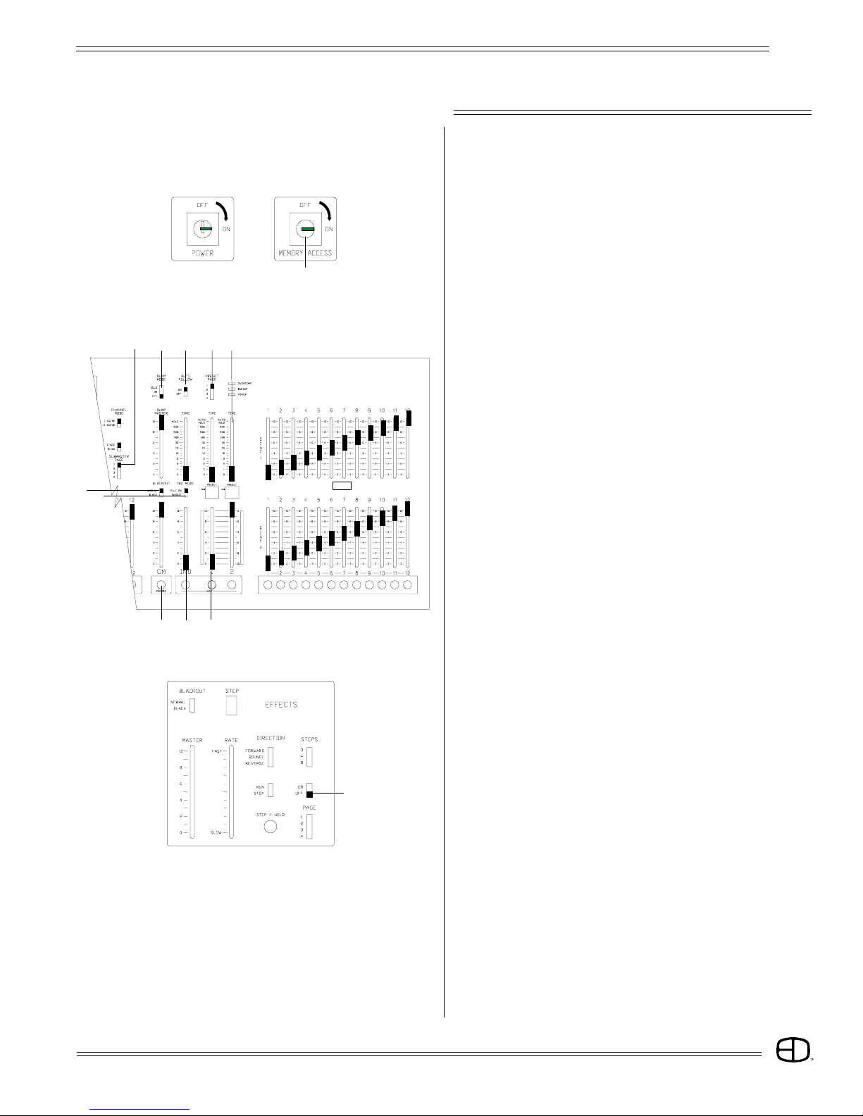
PREPARATION
If you plan to follow the examples set on the following pages,
make sure the front panel controls are set in the following
positions:
01. Memory access switch keyed 'On'
02. Grand Master at 100%
03. Blackout Switch at Normal
04. Time Faders at '0'
05. Ind Fader at '0'
06. Ind Switch at 'Pile-On'
07. Preset Page at '1'
08. Submaster Page at '1'
09. Auto Follow 'On'
10. Fader 1 & 2 split and set at '0'
11. Bump Switch set 'Off'
12. Effect Switch set 'Off'
If you plan to address the dimmer bank, make sure the data
cable is plugged into the back of the console and the output
switch is set to the proper protocol.
When the front panel controls match the above outline,
proceed to the next step.
12
Plus
18
SETTING LEVELS
2-SCENE PRESET
OPERATION
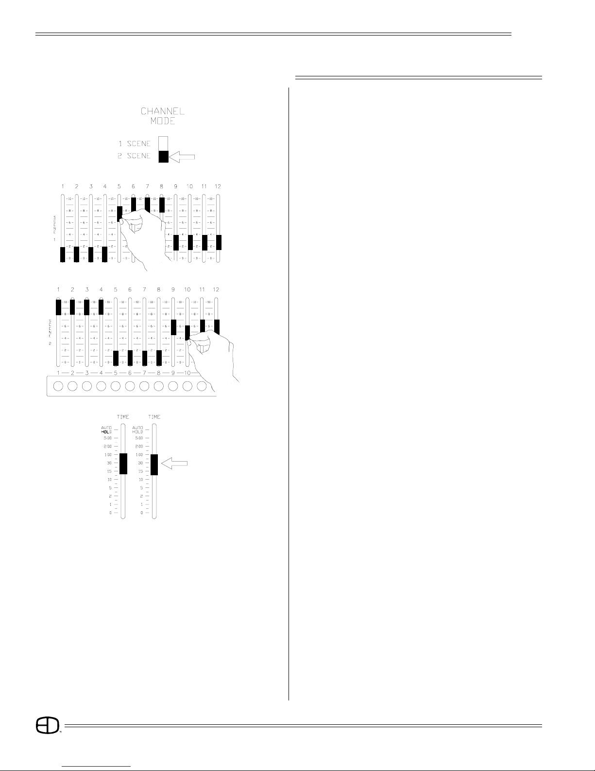
TWO-SCENE MODE:
Set Channel Mode switch to "2-SCENE".
Scene 1 defaults to Fader 1, Scene 2 defaults to Fader 2.
SET FADE TIME:
Set Fader Time sliders to desired fader playback time.
SET SCENE 1 LEVELS:
Set sliders to desired levels.
SET SCENE 2 LEVELS:
Set sliders to desired levels.

Plus
19
OPERATION
2-SCENE PRESET
PLAYBACK
PLAY SCENE:
Move Crossfader 1 to position 10. Bargraph will follow based
on set Fader time.
- 2
- 1
- 1 - 2
CROSSFADE:
Move both Faders together in the same direction. One moves
to '0', the other moves to '10'. Bargraphs follow according to
set fade time.
INDEPENDENT:
Assigned to Scene 1 channels in two-scene mode
or:
Assigned to ALL channels in one-scene mode.

Plus
20
SETTING LEVELS
OPERATION
1-SCENE PRESET
ONE-SCENE MODE:
Set Channel Mode switch to "1-SCENE".
The second row of scene sliders is a continuation of Scene 1,
doubling the console channel capacity.
INDEPENDENT FADER is assigned top and bottom row of
channels in one-scene mode.
SET SCENE 1 LEVELS:
Set sliders to desired levels for Scene1.
1 2
H- HOLDING FEATURE:
Press and hold (RECORD);
Press (LOAD) under Fader 1.
Fader window displays 'H -'. Fade time is captured.
(With "Holding" active, channels and levels are stored for playback
and are no longer affected by slider positions.)
SET SCENE LEVELS:
Set Scene 1 sliders and Scene 2 sliders to levels desired for
Scene 2.
SET FADE TIME:
Set Fader 2 Time Slider to desired fader playback time.
SET FADE TIME:
Set Fader Time sliders to desired fader playback time
Table of contents
Other Electronics Diversified Music Mixer manuals

Popular Music Mixer manuals by other brands


Toa
Toa M-243 operating instructions

LA Audio
LA Audio MX41 Product overview and specifications

Podium Pro Audio
Podium Pro Audio MX1204 user manual

Electro-Voice
Electro-Voice Automatic Microphone Mixer 2509 instruction manual

Behringer
Behringer PRO MIXER Series quick start guide

AUSTRALIAN MONITOR
AUSTRALIAN MONITOR SM12 brochure


