Montarbo MC12 User manual


FRONT PANEL
REAR PANEL
2
1
2
3
4
5
6
7
9
8
10
11
12
13
14
15
16
17
21 22
23
24
31
33
30
34
32
18
26
27
19
20
28
29
25
Montarbo
MC12
MADE IN ITALY
35
36
__________________________________________
__________________________________________
__________________________________________
__________________________________________
__________________________________________
__________________________________________
__________________________________________
__________________________________________
INDICE
Pannello frontale e posteriore
Controlli e connessioni
Importante !
Appendix:
◗Dati tecnici
◗Schema a blocchi
◗Connessioni
◗ Esempi di collegamento
3
2
4 - 5
6
12
13
14 - 16
17
ITALIANO
Il lampo con la freccia inserito in un triangolo equilatero avvisa l'utilizzatore circa la
presenza di 'tensione pericolosa', senza isolamento, all'interno dell'apparecchio che
potrebbe essere sufficientemente alta da generare il rischio di scossa elettrica.
Il punto esclamativo inserito in un triangolo equilatero avvisa l'utilizzatore circa la
presenza di importanti istruzioni per l'utilizzo e per la manutenzione nella documen-
tazione che accompagna il prodotto.
IMPORTANTE ! Norme di sicurezza
ATTENZIONE !
Nell'interesse della propria e della altrui sicurezza, e per non
invalidare la garanzia, si raccomanda una attenta lettura di
questa sezione prima di adoperare il prodotto.
-Questo apparecchio è stato progettato e costruito per venire utilizzato
come mixer nel contesto tipico di un sistema di amplificazione sonora, e/o
di un sistema di registrazione sonora.
L'utilizzo per scopi diversi da questi non è contemplato dal costruttore, ed
avviene pertanto sotto la diretta responsabilità dell'utilizzatore/installatore.
Per evitare il rischio di incendio e/o di folgorazione:
•Non esporre il prodotto alla pioggia non utilizzarlo in presenza di eleva-
ta umidità o vicino all'acqua. Non lasciare penetrare all'interno dell'appa-
recchio e dell'alimentatore esterno alcun liquido, né alcun oggetto solido.
In caso ciò avvenga, scollegare immediatamente l'apparecchio dalla rete
elettrica e rivolgersi ad un servizio di assistenza qualificato prima di
adoperarlo nuovamente.
•Prima di collegare l'alimentatore alla rete elettrica assicurarsi che la
tensione corrisponda a quella indicata sull'alimentatore stesso.
•Utilizzare solamente l'alimentatore esterno fornito con il mixer. Nel caso
in cui l'alimentatore necessiti di sostituzione, utilizzare esclusivamente un
ricambio originale.
•Non appoggiare alcun oggetto sul cavo di collegamento con l'alimenta-
tore. Non posarlo dove possa costituire intralcio e causare inciampo. Non
schiacciarlo e non calpestarlo.
•Durante il funzionamento non coprite il mixer e non tenetelo dentro a
contenitori che possano ostruire la circolazione d'aria (necessaria al raf-
freddamento).
•Prima di effettuare qualsiasi spostamento del prodotto già installato
o in funzione, rimuovere tutti i cavi di collegamento.
-Nel predisporre l'apparecchio all'utilizzo, assicurarsi che la forma e la
por
tata della superficie di appoggio siano idonee a sostenerlo.
-
Per evitare urti riservate come luogo per l'istallazione del prodotto un'area
protetta inaccessibile a personale non qualificato. Qualora l'apparecchio
venga utilizzato in presenza di bambini e animali, si rende necessaria una
strettissima sorveglianza.
-Questo prodotto utilizzato insieme a cuffie o a casse acustiche è in grado
di generare pressioni acustiche molto elevate, pericolose per la salute del
sistema uditivo. Evitarne quindi l'utilizzo ad elevati o fastidiosi livelli acustici.
Non esporre i bambini a forti sorgenti sonore.
ATTENZIONE !
Questo apparecchio e l'alimentatore esterno non contengono
parti interne destinate all'intervento diretto da parte
dell'utilizzatore. Per evitare il rischio di incendio e/o folgorazione,
non aprirli. Per qualsiasi intervento di manutenzione o riparazio-
ne, rivolgersi alla Elettronica Montarbo srl e/o a personale
altamente qualificato specificamente segnalato da questa.

4
CONTROLLI E CONNESSIONI
CANALE D'INGRESSO STEREO
10 ➤GAIN: come nel canale mono.
11 ➤H.F / M.F / L.F: come nel canale mono.
12 ➤AUX: come nel canale mono.
13 ➤EFF: come nel canale mono.
14 ➤BAL: controllo bilanciamento. Permette di regolare il livello
relativo destro/sinistro del segnale stereo del canale nelle uscite
master L/R. Se il canale viene usato in mono diventa un comando
PAN (panorama).
15 ➤VOLUME del canale.
16 ➤PEAK: come nel canale mono.
●connessioni:
17 ➤L/R: ingressi linea sbilanciati jack per il collegamento di stru-
menti stereo. Per collegamenti mono utilizzare l'ingresso 'R/mono'.
MANDATA E RITORNO EFFETTI ESTERNI
18 ➤EFF SEND: controllo di volume per la mandata effetto esterno.
Regola il livello del segnale presente sull'uscita 'EFF SEND' che è la
miscelazione dei segnali inviati dalle mandate dei singoli canali.
19 ➤EFF RETN: controllo di volume per il ritorno effetto esterno
(stereo). Regola il livello di segnale del ritorno effetto esterno.
20 ➤EFF BAL: bilanciamento stereo dell’effetto esterno. Regola la
quantità di effetto da inviare alle uscite master e Control Room L/R.
●
connessioni:
21 ➤EFF SEND: mandata all'effetto esterno (sbilanciato).
22 ➤EFF RETN L/R: 2 ingressi jack sbilanciati per il ritorno stereo
dell'effetto.
• Sono utilizzabili anche come 2 ingressi linea extra.
■Collegare la presa EFF SEND all'ingresso dell'effetto esterno.
■Collegare le prese EFF RETN L/R (del ritorno effetti stereo) alle
uscite 'only effect ' L ed R dell'effetto esterno.
• Per un effetto mono collegare l'uscita
'only effect' dell'effetto alla presa 'R/mono'
■Utilizzare i controlli EFF di ogni canale per regolare la quantità di
segnale da inviare all'effetto esterno, il controllo EFF SEND (18) per
regolare la quantità di segnale da inviare all'uscita 'EFF SEND',
ed i controlli EFF RETN e EFF BAL (19 e 20) per regolare il ritorno
dell'effetto e le quantità dello stesso da inviare ai master 'L/R'.
☛
Figura 4pag. 16
N.B: Anzichè dell'uscita EFF
SEND, ci si può servire dell'uscita AUX (se non è impe-
gnata per i monitor). In tal caso il segnale dell'effetto esterno sarebbe regolabile
mediante la mandata AUX di ogni canale e quindi totalmente indipendente dai
volumi dei canali.
☛
Figura 5pag. 16
CANALE D'INGRESSO MONO
1 ➤GAIN: controlla il guadagno dello stadio di ingresso,
permettendo il collegamento di sorgenti (sia microfoni che linee)
aventi segnali di uscita estremamente variabili.
Come regola generale, al fine di contenere al minimo il rumore,
consigliamo di regolare il GAIN al massimo livello possibile,
evitando però che l'indicatore di picco (PEAK) si accenda.
2 ➤H.F / M.F / L.F. Equalizzazione a 3 bande.
H.F: controlla il livello delle frequenze alte. La frequenza di
intervento è 15kHz, l'accentuazione/attenuazione 15dB.
M.F: controlla il livello delle frequenze medie. La frequenza di
intervento è 600Hz, l'accentuazione/attenuazione 15dB.
L.F: controlla il livello delle frequenze basse. La frequenza di
intervento è 50Hz, l'accentuazione/attenuazione 15dB.
N.B: Girando la manopola in senso orario si ottiene una accentuazione, in
senso antiorario una attenuazione. In posizione centrale la risposta è lineare.
3 ➤AUX: volume mandata ausiliaria. Permette di regolare la
quantità di segnale del canale nell'uscita ausiliaria (dipende dal
controllo di tono ed è indipendente dal volume del canale).
4 ➤EFF: volume mandata effetto. Permette di regolare la
quantità di segnale del canale da inviare all'effetto esterno
(EFF SEND). Dipende dal controllo di tono e volume del canale.
5 ➤PAN: controllo di panorama. Permette di posizionare il
segnale (del canale) nell’immagine stereo inviandolo in quantità
maggiore o minore alle uscite master e Control Room L/R.
6 ➤VOLUME del canale.
7 ➤PEAK: indicatore LED di picco (clipping). Si accende quando il
livello del segnale è prossimo alla distorsione. Il segnale è control-
lato contemporaneamente in due punti del canale: dopo l'amplifi-
catore di ingresso (micro e linea) e dopo l'equalizzatore.
Se il LED PEAK si accende concontinuità, è necessario ridurre il
guadagno di ingresso (GAIN) o regolare diversamente l'equalizza-
zione del canale riducendo l'esaltazione introdotta dai comandi
HF, MF, LF.
●connessioni:
8 ➤MIC: ingresso microfonico bilanciato, con connettore XLR
per il collegamento di microfoni.
9 ➤LINE/INSERT: ingresso linea sbilanciato con connettore jack per
il collegamento di strumenti e sorgenti di segnale ad alto livello.
Incorpora anche la connessione Insert, utilissima per trattare canali
diversi, con apparecchi esterni, singolarmente.
N.B: Non collegare strumenti (o altre sorgenti ad alto livello) all'ingresso MIC !
(questo comporterebbe distorsione dovuta al segnale eccessivo).
Non collegare microfoni all'ingresso LINE ! (il segnale sarà di basso livello e
qualità).

CONTROLLI E CONNESSIONI
5
SEZIONE MASTER
23 ➤L/R MASTER: livelli generali per le uscite master L (sinistra)
ed R (destra).
24 ➤L/R LEVEL: 2 rampe di LED indicano il livello delle uscite
master L ed R.
25 ➤PROCESSOR: premendo questo pulsante si attiva un processo-
re in grado di modificare il contenuto armonico delle uscite master
L ed R consentendo di ottenere un suono 'corposo' anche a livelli di
ascolto bassi (molto utile quindi per piano-bar e simili).
Tale processore agisce solo sulle uscite master L/R.
26 ➤CTRL ROOM: controllo di livello per l'uscita stereo CTRL ROOM
27 ➤AUX VOL: controlla il volume dell'uscita ausiliaria (monitor).
L'uscita master monitor è la miscelazione di tutte le mandate AUX
dei singoli canali.
28 ➤TAPE IN: volume dell’ingresso Tape.
29 ➤PHONES VOL: volume dell’uscita cuffia stereo.
●connessioni:
30 ➤L/R MASTER: uscite master L ed R per il collegamento di
finali di potenza o casse acustiche amplificate (jack sbilanciati).
■Collegare le prese di uscita LEFT - RIGHT agli ingressi dei finali
di potenza o delle casse acustiche autoamplificate.
Regolare i volumi di ogni canale ed i controlli delle uscite master
L (sinistra) R (destra).
Ogni uscita può pilotare fino a 10 casse acustiche autoamplificate
o finali di potenza collegati in parallelo.
☛
Figura 1A, 1B, 1C pag. 14
31 ➤CTRL ROOM L/R: uscite Control Room L/R. Sono una duplica-
zione delle uscite master L/R (jack sbilanciati).
Negli utilizzi in piano-bar, ristoranti, club, ecc.. queste uscite servo-
no in particolare per pilotare ulteriori casse amplificate collocate in
altre sale (per le quali potrebbe essere necessaria una diversa rego-
lazione del volume), oppure monitor amplificati, per avere un con-
trollo diretto del segnale di uscita L/R. Nelle applicazioni in studio il
loro utilizzo tipico è per i monitor di regia.
Il volume di queste uscite viene regolato mediante il comando
CTRL ROOM indipendentemente dai livelli delle uscite master L/R.
Ognuna delle due uscite jack può pilotare fino a 10 casse amplifica-
te o finali di potenza.
☛
Figura 2A pag. 15
L'uscita CTRL ROOM può anche essere utilizzata per collegare un
mixer di dimensioni più grandi. In tal caso l'MC12 serve da mixer
ausiliario. Alle uscite master L/R possono essere collegate 2 casse
acustiche attive per ascolto personale.
☛
Figura 2B pag. 15
32 ➤AUX: uscita ausiliaria/monitor (jack sbilanciato). Può pilotare
fino a 10 casse monitor autoamplificate, collegate in parallelo.
■Collegare l'uscita AUX all'ingresso del monitor amplificato.
Regolare le mandate AUX di ogni canale ed il volume AUX VOL.
☛
Figura 3pag. 16
33 ➤TAPE IN/OUT L/R: ingressi e uscite (prese PIN-RCA) per il
collegamento di un registratore stereo.
■Collegare le prese TAPE OUT L/R del mixer agli ingressi (line in)
del registratore e le uscite (line out) del registratore alle prese TAPE
IN L/R del mixer. Se gli ingressi TAPE IN non vengono utilizzati, si
consiglia di tenere al minimo il volume TAPE IN.
■ Per riprodurre nastri già registrati porre il registratore in riprodu-
zione e regolare opportunamente il volume 'TAPE IN' del mixer
(ed i volumi di uscita del registratore, se presenti).
■ Per registrare dall'impianto: porre il registratore in registrazione
e regolare opportunamente i volumi di ingresso del registratore.
Porre al minimo il volume di uscita del registratore. Nel caso in cui
il vostro registratore non disponga di questo controllo, scollegare i
cavetti dalle prese TAPE IN. Il segnale inviato al registratore non
dipende dalla regolazione dei volumi master L/R.
☛
Figura 6pag. 16
N.B: Gli ingressi TAPE IN L ed R sono normali ingressi di linea ed è perciò possibile
utilizzarli per collegare qualsiasi segnale di linea (ad esempio le uscite di un mixer,
strumenti, expander...).
☛
Figura 5pag. 16
34 ➤PHONES OUT: presa jack per cuffia stereo.
35 ➤Presa DIN per il collegamento dell'alimentatore esterno
(fornito insieme all'MC12).
36 ➤Presa di terra supplementare.

IMPORTANTE!
AVVERTENZE
☞Evitate di esporre il mixer e l'alimentatore a fonti di calore, a
irradiazioni solari dirette, a vibrazioni eccessive.
☞Evitate l’uso e il deposito in ambienti eccessivamente polverosi o
umidi, e soprattutto non esponete il mixer e l'alimentatore alla
pioggia: eviterete così cattivi funzionamenti, deterioramento
anticipato delle prestazioni ed anche il rischio di scosse elettriche ed
incendi.
☞Evitate di utilizzarlo vicino a forti fonti di radiazioni elettromagne-
tiche (videomonitor, cavi elettrici di alta potenza): ciò può provocare
una diminuzione della qualità audio.
☞Prima di qualsiasi spostamento scollegate tutti i cavi.
☞Non forzate i comandi (manopole, interruttori).
☞Per rimuovere la polvere dal pannello usate un pennello o un
soffio d’aria. Non usate detergenti o solventi.
☞In caso di necessità di assistenza, rivolgetevi alla Elettronica
Montarbo srl o a personale altamente qualificato.
INSTALLAZIONE ED USO
☛Collegamento alla rete:
• utilizzare solo l'alimentatore fornito a corredo dell'apparecchio;
• accertarsi che la tensione di rete corrisponda a quella indicata
sull’alimentatore;
• inserire ed avvitare il connettore DIN 5 poli;
• collegare l'alimentatore a rete.
☛Utilizzare cavi di collegamento e connettori di qualità.
☛Utilizzare cavi schermati per tutti i collegamenti.
☛Prima di collegare o scollegare l'alimentatore alla rete, mettete
al minimo i potenziometri delle uscite master.
6
COLLEGAMENTI E REGOLAZIONI INIZIALI
❉Collegare le casse acustiche attive (o finali di potenza con le casse
passive).
❉Collegare i microfoni agli ingressi XLR e gli strumenti agli ingressi
jack. ☛Non collegate i microfoni agli ingressi LINE!
❉Prima di accendere l'apparecchio, mettere tutti i volumi al
minimo.
❉Dopo avere acceso l'apparecchio, regolare i controlli di guadagno
di ogni canale al minimo, i controlli di tono e panorama in posizione
centrale, le mandate ausiliarie e le mandate effetto al minimo.
☛Per ottimizzare la dinamica di ogni canale, in base alle diverse
fonti di segnale, vi consigliamo di effettuare le seguenti operazioni:
- utilizzando il microfono (collegato alla presa XLR) nelle condizioni
di impiego a voi consuete, portare il comando GAIN in posizione
tale da fare illuminare il LED di picco (PEAK)
- a tal punto diminuire il guadagno di quel tanto da fare spegnere il
LED di picco e regolare poi il potenziometro di volume del canale.
N.B: il LED di picco del canale è influenzato esclusivamente dal controllo di gua-
dagno e dai controlli di tono.
-un canale per volta, effettuare questa operazione su tutti i canali
utilizzando le fonti di segnale per essi predisposte (voce femminile,
voce maschile, strumenti...) e nelle condizioni di impiego il più
possibile reali.
❉Portare i volumi master L/R (23) ed il volume 'AUX VOL' (27) in
posizione centrale; a questo punto alzare il volume (6/15) di ogni
singolo canale secondo le proprie esigenze.
__________________________________________
__________________________________________
__________________________________________
__________________________________________
__________________________________________
__________________________________________
__________________________________________
__________________________________________
__________________________________________
CONTENTS
Front and rear panels
Controls and connections
Important !
Appendix:
◗Technical specifications
◗Block diagram
◗
Connections
◗
Connection examples
2
8 - 9
10
12
13
14 - 16
17
ENGLISH
7
IMPORTANT ! Safety instructions
The lighting flash with arrowhead symbol within an equilateral triangle, is intended
to alert the user to the presence of uninsulated "dangerous voltage" within the
product's enclosure, that may be of sufficient magnitude to constitute a risk of
electric shock to humans.
The exclamation point within an equilateral triangle, is intended to alert the user
to the presence of important operating and maintenance (servicing) instructions in
the literature accompanying the product.
WARNING !
In order to protect your own and others' safety and to avoid
invalidation of the warranty of this product, please read this
section carefully before operating this product.
-This product has been designed and manufactured for being operated as
mixing console in the applications tipical of a sound reinforcement system
or of a sound recording system. Operation for purposes and in applications
other than these has not been covered by the manufacturer in the design
of the product, and is therefore to be undertaken at end user's and/or
installer's sole risk and responsability.
To avoid the risk of fire and/or electric shock:
•Never expose this product to rain or moisture, never use it in proximity of
water or on a wet surface. Never let any liquid, as well as any object, enter
the mixer and the power supply. In case, immediately disconnect it from
the mains supply and refer to servicing before operating it again.
•Before connecting the power supply to the mains socket, always make
sure that the voltage on the mains outlet corresponds to that stated on
the power supply.
•Always use the original power supply unit. In case the power supply
needs to be substituted, use exclusively an original spare part.
•Never place any object on the power supply cable. Never lay it on a
walkway where one could trip over it. Never press or pinch it.
•During operation do not cover the mixer and do not keep it in
containers which may prevent correct air circulation.
•Before attempting to move the product after it has been installed,
remove all the connections.
-Before placing the product on a surface of any kind, always make sure
that its shape and load rating will safely match the product's size and
weight.
-
To avoid shocks always reserve a protected area with no access to unqualified
personnel as installation site of the product. In case the product is used near
children and animals closest supervision is necessary.
-This product in combination with headphones or speakers can generate
very high acoustic pressures which are dangerous for the hearing system.
Do not operate for a long period of time at a high or unconfortable volume
level. Never expose children to high sound sources.
CAUTION !
This product and its power supply unit do not contain user
serviceable parts. To prevent fire and/or electrical shock, never
open them. Maintenance and servicing must be carried out by
the official Montarbo Distributor in your State or by qualified
personnel specifically authorized by the distributor.

CONTROLS AND CONNECTIONS
8
MONO INPUT CHANNEL
1 ➤GAIN: adjust the gain (sensitivity) of the line and mic inputs,
allowing connections of signal sources (both line and mic level)
having a wide range of signal level. As a practical rule, the GAIN
control must be set to the maximum allowable level that will not
activate the peak level indicator (PEAK). This will maximize the
signal to noise ratio.
2 ➤H.F / M.F / L.F: 3-band Equalizer
H.F.: adjusts the amount of high frequencies giving up to 15dB of
boost or cut at 15kHz.
M.F.: adjusts the amount of mid frequencies giving up to 15dB of
boost or cut at 600Hz.
L.F: adjusts the amount of low frequencies giving up to 15dB of
boost or cut at 50Hz.
Note: Turning the control clockwise increases the amount of high, mid or low
frequencies, counter-clockwise decreases it. The response is flat at the center
position.
3➤AUX: auxiliary send volume. It sets the signal level of the
channel in the auxiliary outputs (post-eq, pre-volume).
4➤EFF: effect send volume (post-volume and post-eq).
It determines how much effect signal from the external effect
device is added to the input signal of the channel.
5➤PAN: this control allows to place the channel’s input signal
within the stereo image by assigning more or less of the signal
to the left or right Control Room and master outputs.
6➤Channel VOLUME control.
7➤PEAK: peak LED indicator. It lights when the signal level is
approaching the maximum (clipping) allowable level. The signal
is sampled in two points of the channel's signal path: after the
input amplifier (micro and line) and after the equalizer.
If the LED is continuously lighted, you must either reduce the
input GAIN or modify the equalizer settings, reducing the boosts
introduced by the level controls HF, MF and LF.
●
connections:
8➤MIC: balanced XLR microphone input for microphones.
9➤LINE/INSERT: unbalanced jack line input (for instruments and
high level sources). Also usable as stereo insert to process single
channels independently.
Note:
Do not connect instruments or other high level sources to the MICRO inputs
(this will result in distortion due to excessive signal level).
Do not connect microphones to the LINE inputs (the resulting signal will be
of low level and low quality) .
STEREO INPUT CHANNEL
10 ➤GAIN: same as in the mono channel.
11 ➤H.F / M.F / L.F: same as in the mono channel.
12 ➤AUX: same as in the mono channel.
13 ➤EFF: same as in the mono channel.
14 ➤BAL: stereo balance. Allows to adjust the level of the input
signal in the left or right master outputs. If the channel is used as
a mono channel it becomes a PAN control.
15 ➤channel VOLUME control.
16 ➤PEAK: same as in the mono channel.
●
connections:
17 ➤L/R: unbalanced jack line inputs for stereo instruments.
For mono connections use 'R/mono' input.
EXTERNAL EFFECTS SEND AND RETURN
18 ➤EFF SEND: level control for the external effect send.
It is the mix of the signals sent from the EFF SEND volumes on each
channel and sets the level of the signal appearing at the 'EFF SEND'
jack output.
19 ➤EFF RETN: level control for the external stereo effect return.
Sets the signal level of the external effect return.
20 ➤EFF BAL: stereo balance of the external effect.
Allows to adjust the level of the stereo signal of the effect in the
L and R Control Room and master outputs.
●
connections:
21 ➤EFF SEND:unbalanced jack output sockets for the effect send.
22 ➤EFF RETN L/R: 2 unbalanced jack inputs for the external stereo
effect return.
• They can also be used as 2 extra line inputs.
■Connect the EFFSEND output to the input of the external effect.
■Connect the L and R EFF RETN inputs to the L and R 'only effect'
outputs of the external effect.
•For a mono effect connect its 'only effect' output to the 'R / mono' socket.
■Use the EFF controls on each channel to determine the quantity
of channel's signal to be sent to the external effect, the EFF SEND
control (18) to determine the quantity of signal to be sent to the 'EFF
SEND' output, and the EFF RETN and EFF BAL (19and 20) controls to
adjust the effect return level in the master 'L/R' outputs.
☛
see fig. 5, page 16
Note: The AUX output (if not used as monitor output) can be used in place of
the EFF SEND output. In this case the signal of the external effect is adjusted by
means of the AUX send control on each channel and it is thus fully independent
from the channel volume.
☛
see fig. 4, page 16

CONTROLS AND CONNECTIONS
9
MASTER SECTION:
23 ➤L/R MASTER: volume controls for the left and right master
outputs.
24 ➤L/R LEVEL: two 12 segment LED arrays give istantaneous
reading of L and R outputs level.
25 ➤PROCESSOR: pushing this button activates an internal
processor which operates the L and R master outputs allowing
to obtain a 'full-bodied' sound even with a low sound level (very
useful when performing in clubs, small venues etc.).
This processor has effect only on the L/R outputs.
26 ➤CTRL ROOM: level control for the control room stereo
output.
27 ➤AUX VOL: master volume control for the auxiliary/monitor
output. The monitor master output is the mix of the individual
channel's AUX sends.
28 ➤TAPE IN: sets the level of the signal at the 'Tape in'
socket of the mixer.
29 ➤PHONES VOL: level control for the stereo phones output.
●
connections:
30 ➤L/R MASTER: L/R master outputs (unbalanced jacks) for the
connection of power amplifiers or active speaker enclosures.
■Connect the L/R master outputs to the inputs of the self-powered
speaker enclosures or to the inputs of the power amplifiers.
■Adjust the volume control on each channel as well as the L/R
master volume controls.
■Each output can drive up to 10 parallel connected active speaker
enclosures or power amplifiers.
☛
see fig. 1A, 1B, 1C page 14
31 ➤L/R CTRL ROOM : L/R Control Room outputs (unbalanced
jacks), with independent volume control. They provide a duplication
of the L/R master outputs signal enabling thus to feed a second
PA-System in live performances to allow different audiences to
listen at different sound levels (for example louder on dance floor
and softer at the bar). In studio applications they are used to drive
the control room monitors.
The output level is adjusted by means of the CRTL ROOM level
control, which is unaffected by the L/R master outputs volume
levels.
Each output can drive up to 10 powered speaker enclosures or
power amplifiers.
☛
see fig. 2A, page 15
The CONTROL ROOM may be connected to the inputs of a larger
mixer. In this case the MC12 may be used as an auxiliary mixer and
the L/R master outputs may drive two personal monitor active
speakers.
☛
see fig. 2B page 15
32 ➤AUX: auxiliary/monitor output (unbalanced jack).
■Connect the AUX socket to the input of the self-powered stage
monitor.
The 'AUX' controls on each channel are the monitor send controls.
Each output can drive up to 10 parallel connected powered
monitors.
☛
see fig. 3, page 16
33 ➤L/R TAPE IN/OUT: PIN in-out sockets. They allow connection
to a stereo tape recorder.
■Connect the L/R TAPE OUT sockets to the inputs of the tape
recorder (line in) and the outputs of the tape recorder (line out) to
the L/R TAPE IN sockets of the mixer. If the TAPE IN inputs are not
used, it is suggested to keep the volume control fully closed, to
keep output noise to a minimum.
■For playback: switch the recorder to play and adjust the TAPE IN
VOL control on the mixer (and the output volumes of the tape
recorder, if available).
■For recording: switch the recorder to the 'record' mode and
adjust the input volume of the tape recorder. Set the output
volume control of the tape recorder to its lowest setting. In case
your tape recorder has no output volume control, disconnect the
cables from the TAPE IN sockets. The signal sent to the tape
recorder is unaffected by the L/R master faders settings.
☛
see fig. 6, page 16
Note: The L/R Tape inputs are a standard stereo line input. You can thus use
them to connect any line signal (such as the L/R outputs of a second mixer,
instruments expanders...).
☛
see fig. 5, page 16
34 ➤PHONES OUT: output for stereo phones.
35➤AC POWER: DIN socket for the connection of the external
power supply unit (supplied with the MC12).
36 ➤Auxiliary GROUND socket.

10
IMPORTANT!
PRECAUTIONS
☞Never expose the mixer and the power supply to heat sources,
direct sunlight, excessive vibrations or mechanical shocks.
☞Avoid operating and storing the mixer and the power supply in
damp or dusty places and absolutely never expose it to rain: this
will avoid malfunctions, premature degrading of specifications and
the risk of electrical shocks and fire hazard.
☞Avoid using it close to strong sources of electromagnetic
interferences (e.g. video monitors, high power electrical cabling).
This may lead to degradation of audio quality.
☞Before moving the mixer disconnect all cables.
☞Never apply excess force to the controls (knobs, potentiometers).
☞Use a soft brush or a jet of air to clean the panel. Do not use
solvents or detergents.
☞If service is needed, refer to qualified service personnel only or to
the Montarbo distributor in your country.
INSTALLATION AND USE
☛When connecting the mixer to the mains supply:
• use only the external power supply unit supplied with the MC12;
• check that mains voltage corresponds to the voltage indicated
on the power supply;
• connect the power supply to the mixer with the 5-pin DIN
connector;
• connect the power supply to the mains socket.
☛Always use quality cables and connectors.
☛Use shielded cables for all your connections.
☛Before switching on or off the mixer, 'close' (set to minimum)
the outputs controls. This will avoid switching noises that may
cause damages to loudspeakers.
PRELIMINARY CONNECTIONS AND SETTINGS
❉Connect the active speakers (or the power amps), the micro-
phones, the instruments and any auxiliary equipment.
❉Before turning on the mixer, set the channel volume controls and
the master volume controls to their lowest settings.
❉Switch on the unit and turn the gain controls to their lowest
settings the tone controls and panpots to the middle position, and
the auxiliary and effect sends anti-clockwise to their lowest settings.
☛To optimize the dynamics of each channel according to the
various signal sources, proceed as follows:
- using a microphone (connected to the XLR mic input) in
conditions typical of the intended use, set the GAIN control so as
to cause the Peak LED to illuminate;
- now reduce the GAIN just enough until the peak LED switches off
and adjust the volume.
Note: The channel's peak LED is affected only by the GAIN control and the TONE
controls.
- repeat the above procedure for all the channels, one at a time,
using the signal source assigned to that channel and simulating real
operating conditions as closely as possible.
❉Set the L/R master volume controls (23) and the Aux volume
control (27) to the middle position, and adjust the volume control
(6/15)
of each channel according to your requirements .

APPENDIX
11

TECHNICAL SPECIFICATIONS
12
4
- 60dB / 2,2 kΩ
- 40dB / 10 kΩ
30dB
-128dB
H.F ±15dB@15kHz shelving
M.F ±15dB@600Hz
peaking
L.F ±15dB@50Hz shelving
4
- 46dB / 10kΩ
34dB
-128dB
H.F ±15dB @ 15kHz
M.F ±15dB @ 600Hz
L.F ±15dB @ 40Hz
0dB
100Ω
+22dB
-10dB
10kΩ
+22dB
0dB
+22dB
L/R, C. Room
0dB
100Ω
+22dB
600Ω
25Hz÷30kHz (+0 / -2dB)
<0,01%
82dB
-10dB
-10dB
200÷600Ω
32,2 x 5 x 26,3 cm
2,5 Kg
TECHNICAL SPECIFICATIONS
Mono Input channels:
micro (sensitivity / impedance)
line (sensitivity / impedance)
channel gain control range
equivalent input noise
equalization
Stereo Input channels:
line L/R (sensitivity / impedance)
channel gain control range
equivalent input noise
equalization
External effect send:
nominal level
impedance
max level
External effect return:
nominal level
impedance
max level
Aux Output
nominal level
max level
Master outputs:
nominal level
impedance
max level
min load impedance
frequency response
THD
S.N.R
Tape in: nominal level
Tape out: nominal level
Headphones: load impedance
Dimensions:
Weight:

13
BLOCK DIAGRAM
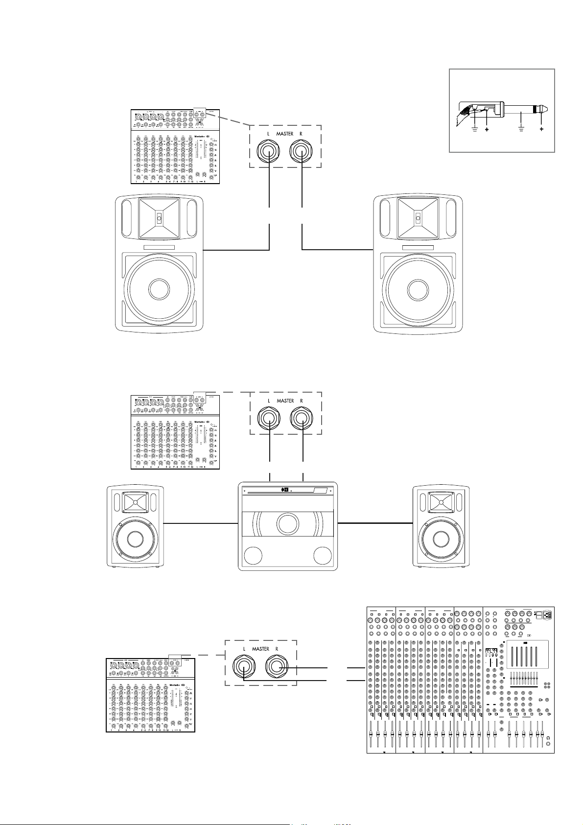
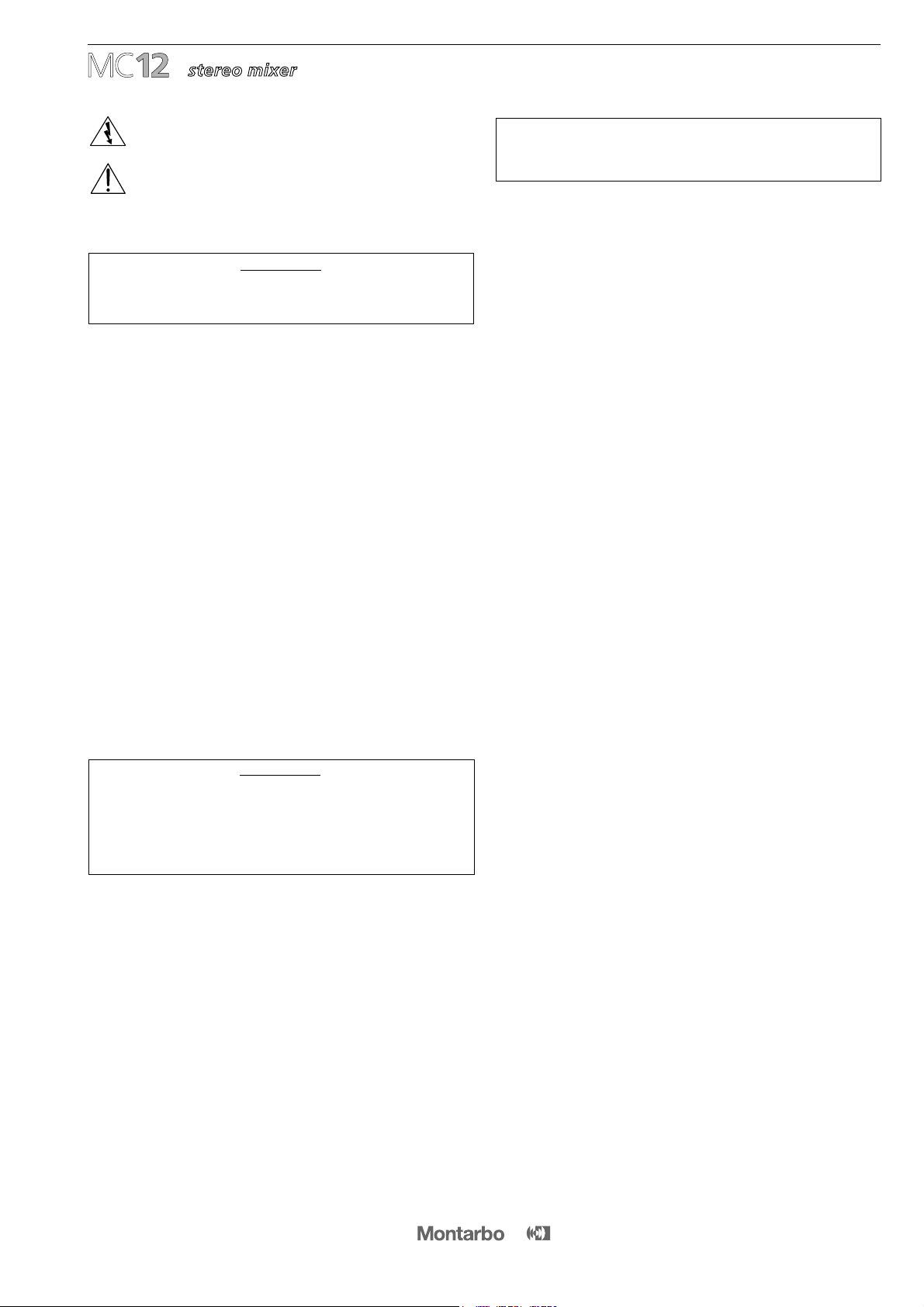
FIG. 1A: L-R MASTER OUTPUTS
Connection of power amplifiers or active speaker
enclosures.
CONNECTIONS
14
JACK sockets:
☞
MASTER OUTPUTS
mono JACK plug
ACTIVE SUBWOOFER
112SA
Montarbo
ACTIVE SPEAKER ENCLOSURE
FIG. 1B: L-R MASTER OUTPUTS
Connection of an active subwoofer.
FIG. 1C: L-R MASTER OUTPUTS
Connection of a mixer. You can use MC12 as an
auxiliary mixer
ACTIVE SPEAKER ENCLOSURES
ACTIVE SUBWOOFER
ACTIVE SPEAKER ENCLOSURE
Line inLine in
▲▲
▲▲
▲
▲
▲▲
PHANTOM 48V D.C.
LF
HF
B
A
C
D
LINE
INSERT
IN
OUT
GAIN GAINGAINGAIN
MF
B
A
C
D
B
A
C
D
B
A
C
D
LF
HF
MF
LF
HF
MF
LF
HF
MF
MIC
LINE
INSERT
IN
OUT
MIC
LINE
INSERT
IN
OUT
MIC
KHz KHz KHz KHz
521-MN4
E2
E1
ON
PEAK
ON
PEAK
PAN
ON
PEAK
ON
PEAK
E2
E1
PAN
E2
E1
PAN
E2
E1
PAN
R
M
LR
M
LR
M
LR
M
L
PFL PFL PFL PFL
PHANTOM 48V D.C.
LF
HF
B
A
C
D
LINE
INSERT
IN
OUT
GAIN GAINGAINGAIN
MF
B
A
C
D
B
A
B
A
C
D
LF
HF
MF
LF
HF
MF
LF
HF
MF
MIC
LINE
INSERT
IN
OUT
MIC
LINE
INSERT
IN
OUT
MIC
KHz KHz KHz
521-MN4
E2
E1
ON
PEAK
ON
PEAK
PAN
ON
PEAK
ON
PEAK
E2
E1
PAN PAN
E2
E1
PAN
R
M
LR
M
LR
M
LR
M
L
PFL PFL PFL PFL
PHANTOM 48V D.C.
LF
HF
B
A
C
D
LINE
INSERT
IN
OUT
GAIN GAINGAINGAIN
MF
B
A
C
D
B
A
C
D
B
A
C
D
LF
HF
MF
LF
HF
MF
LF
HF
MF
MIC
LINE
INSERT
IN
OUT
MIC
LINE
INSERT
IN
OUT
MIC
KHz KHz KHz
521-MN4
E2
E1
ON
PEAK
ON
PEAK
PAN
ON
PEAK
ON
PEAK
E2
E1
PAN
E2
E1
PAN
E2
E1
PAN
R
M
LR
M
LR
M
LR
M
L
PFL PFL PFL PFL
LINE
LINE
L
MIC
R
(mono)
HF
MF
LF
mono
GAIN GAIN GAIN GAIN
HF
MF
LF
HF
MF
LF
HF
MF
LF
B
A
C
D
B
A
C
D
B
A
C
D
B
A
C
D
LINE
LINE
L
R
(mono)
LINE
LINE
L
R
(mono)
mono mono
MIC MIC
MIC MIC MIC
521-ST4
RL
E2
E1
ON
PEAK
RL
ON
PEAK
BAL
RL
ON
PEAK
RL
ON
PEAK
E2
E1
BAL
E2
E1
BAL
E2
E1
BAL
PFLPFLPFLPFL
ABCDLR
Montarbo
Montarbo
audio mixing system
521
16 /2
BAL
R
2
mute
LRMONO
AUX OUTPUTS
POWER
A B C D
10
3
0
3
20
dB
+
INPUT LEVEL
10
3
0
3
20
dB
+
INPUT LEVEL
48V D.C.
PHANTOM
20 20
B
C
A
BAL
VOL
STEREO DIGITAL
EFFECTSPROCESSORS
MASTER OUTPUTS
1
1EFF.SEND 2
mute
1EFF. FT/SW 2
RR
IN OUT
LL
TAPE
2X 140 - Programs
MontarboDigital Effects Processor
EFFECTSINDEX
00/09 STEREO GEN
10/29 HALO
30/39 ECHO
40/49 ECHO + REVERB
50/59 VOICE REVERB
60/69 PERCUSSION REVERB
70/79 DUAL ECHO + REVERB
80/89 STEREO DUAL ECHO
90/99 EARLY REFLECTION
A0/A9 STEREO FLANGER
B0/B9 STEREOCHORUS
C0/C9 DUAL PITCH CHANGE
D0/D9 PITCH + REVERB
D
D
CC
BB
AA
tone
tone
A
VOL
31 63 125 250 500 1K 2K 4K 8K 16K
PROGRAM PROGRAM
2
STEREO
EFF. RET.
1
STEREO
EFF. RET.
STEREOEFF. RET.
TAPEIN VOL.
PFL
L/R
LF
HF
MF
BAL
RLRL
DD A
D
C
B
PFLONON
EFF.SEND 1
DIGITALSTEREO EFFECTS AUX
PRE
POST
MASTER
ABCD
LR
EFF.SEND 2
PHONESMONO
BAL
LF
HF
MF
LF
HF
MF
LF
HF
MF
PFL PFL PFL
EQ
FLAT
E 2E 1
mono
R
mixer input
L
CONNECTIONS
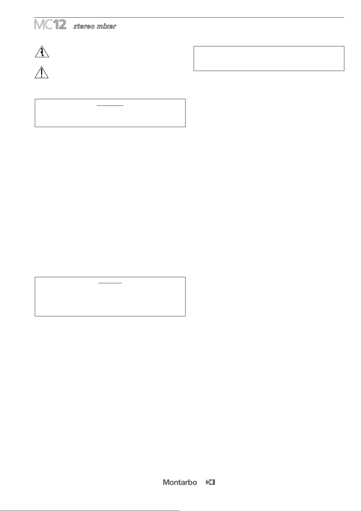
FIG. 2A: L-R CONTROL ROOM OUTPUTS
Connection of active speaker enclosures.
JACK sockets:
☞
CONTROL ROOM
mono JACK plug
15
ACTIVE SPEAKER ENCLOSURES
PHANTOM 48V D.C.
LF
HF
B
A
C
D
LINE
INSERT
IN
OUT
GAIN GAINGAINGAIN
MF
B
A
C
D
B
A
C
D
B
A
C
D
LF
HF
MF
LF
HF
MF
LF
HF
MF
MIC
LINE
INSERT
IN
OUT
MIC
LINE
INSERT
IN
OUT
MIC
KHz KHz KHz KHz
521-MN4
E2
E1
ON
PEAK
ON
PEAK
PAN
ON
PEAK
ON
PEAK
E2
E1
PAN
E2
E1
PAN
E2
E1
PAN
R
M
LR
M
LR
M
LR
M
L
PFL PFL PFL PFL
PHANTOM 48V D.C.
LF
HF
B
A
C
D
LINE
INSERT
IN
OUT
GAIN GAINGAINGAIN
MF
B
A
C
D
B
A
B
A
C
D
LF
HF
MF
LF
HF
MF
LF
HF
MF
MIC
LINE
INSERT
IN
OUT
MIC
LINE
INSERT
IN
OUT
MIC
KHz KHz KHz
521-MN4
E2
E1
ON
PEAK
ON
PEAK
PAN
ON
PEAK
ON
PEAK
E2
E1
PAN PAN
E2
E1
PAN
R
M
LR
M
LR
M
LR
M
L
PFL PFL PFL PFL
PHANTOM 48V D.C.
LF
HF
B
A
C
D
LINE
INSERT
IN
OUT
GAIN GAINGAINGAIN
MF
B
A
C
D
B
A
C
D
B
A
C
D
LF
HF
MF
LF
HF
MF
LF
HF
MF
MIC
LINE
INSERT
IN
OUT
MIC
LINE
INSERT
IN
OUT
MIC
KHz KHz KHz
521-MN4
E2
E1
ON
PEAK
ON
PEAK
PAN
ON
PEAK
ON
PEAK
E2
E1
PAN
E2
E1
PAN
E2
E1
PAN
R
M
LR
M
LR
M
LR
M
L
PFL PFL PFL PFL
LINE
LINE
L
MIC
R
(mono)
HF
MF
LF
mono
GAIN GAIN GAIN GAIN
HF
MF
LF
HF
MF
LF
HF
MF
LF
B
A
C
D
B
A
C
D
B
A
C
D
B
A
C
D
LINE
LINE
L
R
(mono)
LINE
LINE
L
R
(mono)
mono mono
MIC MIC
MIC MIC MIC
521-ST4
RL
E2
E1
ON
PEAK
RL
ON
PEAK
BAL
RL
ON
PEAK
RL
ON
PEAK
E2
E1
BAL
E2
E1
BAL
E2
E1
BAL
PFLPFLPFLPFL
ABCDLR
Montarbo
Montarbo
audio mixing system
521
16 /2
BAL
R
2
mute
LRMONO
AUX OUTPUTS
POWER
A B C D
10
3
0
3
20
dB
+
INPUT LEVEL
10
3
0
3
20
dB
+
INPUT LEVEL
48V D.C.
PHANTOM
20 20
B
C
A
BAL
VOL
STEREO DIGITAL
EFFECTSPROCESSORS
MASTER OUTPUTS
1
1EFF.SEND 2
mute
1EFF. FT/SW 2
RR
IN OUT
LL
TAPE
2X 140 - Programs
MontarboDigital Effects Processor
EFFECTSINDEX
00/09 STEREO GEN
10/29 HALO
30/39 ECHO
40/49 ECHO + REVERB
50/59 VOICE REVERB
60/69 PERCUSSION REVERB
70/79 DUAL ECHO + REVERB
80/89 STEREO DUAL ECHO
90/99 EARLY REFLECTION
A0/A9 STEREO FLANGER
B0/B9 STEREOCHORUS
C0/C9 DUAL PITCH CHANGE
D0/D9 PITCH + REVERB
D
D
CC
BB
AA
tone
tone
A
VOL
31 63 125 250 500 1K 2K 4K 8K 16K
PROGRAM PROGRAM
2
STEREO
EFF. RET.
1
STEREO
EFF. RET.
STEREOEFF. RET.
TAPEIN VOL.
PFL
L/R
LF
HF
MF
BAL
RLRL
DD A
D
C
B
PFLONON
EFF.SEND 1
DIGITALSTEREO EFFECTS AUX
PRE
POST
MASTER
ABCD
LR
EFF.SEND 2
PHONESMONO
BAL
LF
HF
MF
LF
HF
MF
LF
HF
MF
PFL PFL PFL
EQ
FLAT
E 2E 1
mono
FIG. 2B: L-R CONTROL ROOM OUTPUTS
Connection of a mixer. You can use MC12 as an
auxiliary mixer
MontarboMontarbo
MontarboMontarbo
▲
▲
▲
Montarbo
Montarbo
Montarbo
Montarbo
▲
MAIN P.A SYSTEM
PERSONAL MONITORS (active)
▲▲
L R
MASTER OUTPUTS
CONTROL ROOM L/R OUTPUTS
▲
▲
STEREO LINE INPUT
(or 2 mono line inputs)

CONNECTIONS
16
FIG. 4: EFFECT SEND / EFFECT RETURN
Connection of external effects.
JACK sockets:
☞
EFFECT SEND
☞
EFFECT RETURN
mono JACK plug
FIG. 6: L/R TAPE IN/OUT
Hooking up a stereo tape recorder.
PIN - RCA Plug
PIN sockets:
☞
L/R TAPE INPUTS and OUTPUTS
STEREO TAPE RECORDER
line in
line out
R L L R
EXTERNAL EFFECT
OUTPUTS
L R INPUT
FIG. 3: AUX OUTPUT
Connection of active stage monitors
JACK sockets:
☞
AUX OUTPUT
mono JACK plug
ACTIVE MONITOR
FIG. 5: AUX / TAPE-IN or L/R LINE IN
Connection of a second external effect.
EXTERNAL EFFECT
OUTPUTS
L R INPUT
▲
▲
▲▲
▲
▲
▲
OR
stereo
line
input
▲
▲
stereo
line
input
Use the AUX output as effect send
and a stereo line input (OR the stereo
Tape input) as stereo effect return.

☞each output (L-R-Aux) can drive up to 10 parallel
connected power amplifiers or powered enclosures
▲
▲ ▲
R master outputAux output
L master output
▲
micro
line
▲
instrument
▲
▲
▲
▲
L/R
L/R
L/R
L/R
5/6 7/8 9/10 11/12
external stereo effects processor
stereo return
send
active speaker enclosures MT360A
CONNECTION EXAMPLE (a)
▲
▲
▲
▲
active monitor
phones
output
stereo headphones
L/R tape
in/out
stereo tape recorder
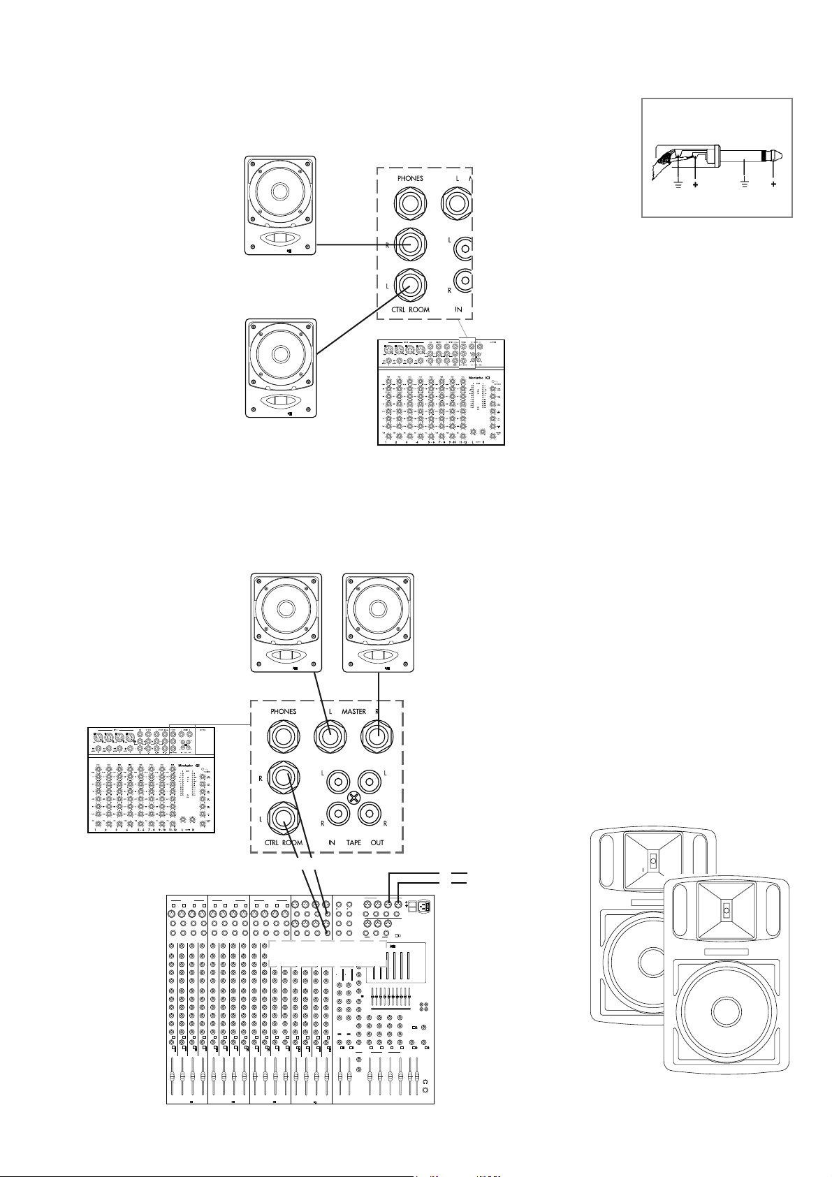
CONNECTION EXAMPLE (b)
Aux output
L/R master outputs
active monitor
▲
▲
17
▲
▲ ▲
▲
▲
▲
L/R Control
room outputs
▲
▲
▲
;;;;;;
;;;;;;
;;;;;;
;;;;;;
;;;;;;
;;;;;;
Montarbo
Montarbo
▲
micro
line
▲
instrument
external stereo effects processor
stereo return
send
▲
▲ ▲
L/R Control
room outputs
▲
▲
;;;;;;
;;;;;;
;;;;;;
;;;;;;
;;;;;;
;;;;;;
Montarbo
Montarbo
active stereo subwoofer 112SA
active speaker enclosures MT180A
stereo inputs
stereo instruments
active speaker enclosures MT360A
ACTIVE SUBWOOFER
112SA
Montarbo
active speaker enclosures MT180A
PHANTOM48V D.C.
LF
HF
B
A
C
D
LINE
INSERT
IN
OUT
GAIN GAINGAINGAIN
MF
B
A
C
D
B
A
C
D
B
A
C
D
LF
HF
MF
LF
HF
MF
LF
HF
MF
MIC
LINE
INSERT
IN
OUT
MIC
LINE
INSERT
IN
OUT
MIC
KHz KHz KHz KHz
521-MN4
E2
E1
ON
PEAK
ON
PEAK
PAN
ON
PEAK
ON
PEAK
E2
E1
PAN
E2
E1
PAN
E2
E1
PAN
R
M
LR
M
LR
M
LR
M
L
PFL PFL PFL PFL
PHANTOM48V D.C.
LF
HF
B
A
C
D
LINE
INSERT
IN
OUT
GAIN GAINGAINGAIN
MF
B
A
C
D
B
A
B
A
C
D
LF
HF
MF
LF
HF
MF
LF
HF
MF
MIC
LINE
INSERT
IN
OUT
MIC
LINE
INSERT
IN
OUT
MIC
KHz KHz KHz
521-MN4
E2
E1
ON
PEAK
ON
PEAK
PAN
ON
PEAK
ON
PEAK
E2
E1
PAN PAN
E2
E1
PAN
R
M
LR
M
LR
M
LR
M
L
PFL PFL PFL PFL
PHANTOM48V D.C.
LF
HF
B
A
C
D
LINE
INSERT
IN
OUT
GAIN GAINGAINGAIN
MF
B
A
C
D
B
A
C
D
B
A
C
D
LF
HF
MF
LF
HF
MF
LF
HF
MF
MIC
LINE
INSERT
IN
OUT
MIC
LINE
INSERT
IN
OUT
MIC
KHz KHz KHz
521-MN4
E2
E1
ON
PEAK
ON
PEAK
PAN
ON
PEAK
ON
PEAK
E2
E1
PAN
E2
E1
PAN
E2
E1
PAN
R
M
LR
M
LR
M
LR
M
L
PFL PFL PFL PFL
LINE
LINE
L
MIC
R
(mono)
HF
MF
LF
mono
GAIN GAIN GAIN GAIN
HF
MF
LF
HF
MF
LF
HF
MF
LF
B
A
C
D
B
A
C
D
B
A
C
D
B
A
C
D
LINE
LINE
L
R
(mono)
LINE
LINE
L
R
(mono)
mono mono
MIC MIC
MIC MIC MIC
521-ST4
RL
E2
E1
ON
PEAK
RL
ON
PEAK
BAL
RL
ON
PEAK
RL
ON
PEAK
E2
E1
BAL
E2
E1
BAL
E2
E1
BAL
PFLPFLPFLPFL
ABCDLR
Montarbo
Montarbo
audio mixing system
521
16/2
BAL
R
2
mute
LRMONO
AUXOUTPUTS
POWER
A B C D
10
3
0
3
20
dB
+
INPUTLEVEL
10
3
0
3
20
dB
+
INPUTLEVEL
48VD.C.
PHANTOM
20 20
B
C
A
BAL
VOL
STEREO DIGITAL
EFFECTSPROCESSORS
MASTER OUTPUTS
1
1EFF.SEND 2
mute
1EFF.FT/SW 2
RR
IN OUT
LL
TAPE
2X140 - Programs
MontarboDigitalEffects Processor
EFFECTSINDEX
00/09STEREOGEN
10/29HALO
30/39ECHO
40/49ECHO+ REVERB
50/59VOICEREVERB
60/69PERCUSSIONREVERB
70/79DUALECHO + REVERB
80/89STEREODUAL ECHO
90/99EARLYREFLECTION
A0/A9STEREOFLANGER
B0/B9STEREO CHORUS
C0/C9DUALPITCH CHANGE
D0/D9PITCH+ REVERB
D
D
CC
BB
AA
tone
tone
A
VOL
31 63 125 250 500 1K 2K 4K 8K 16K
PROGRAM PROGRAM
2
STEREO
EFF. RET.
1
STEREO
EFF. RET.
STEREOEFF.RET.
TAPEINVOL.
PFL
L/R
LF
HF
MF
BAL
RLRL
DDA
D
C
B
PFLONON
EFF.SEND1
DIGITALSTEREOEFFECTS AUX
PRE
POST
MASTER
ABCD
LR
EFF.SEND2
PHONESMONO
BAL
LF
HF
MF
LF
HF
MF
LF
HF
MF
PFL PFL PFL
EQ
FLAT
E2E 1
mono
channels 1-2-3-4
▲
▲
▲
▲
▲
▲
▲
▲
phones
output
stereo headphones
L/R tape
in/out
stereo tape recorder
▲
▲
▲
▲
▲
L/R
L/R
L/R
L/R
5/6 7/8 9/10 11/12
stereo inputs
stereo instruments
channels 1-2-3-4
▲
▲
▲
▲
elettronica
Montarbo
srl
via G. di Vittorio 13
40057 Cadriano di Granarolo
Bologna, Italy
Tel. +39. 051. 76 64 37
Fax. +39. 051. 76 52 26
E-mail: [email protected]
Tlx. 511312 montar i
Le informazioni contenute in questo manuale
sono state attentamente redatte e controllate.
Tuttavia non si assume alcuna responsabilità
per eventuali inesattezze.
Questo manuale non può contenere una
risposta a tutti i singoli problemi che possono
presentarsi durante l'installazione e l'uso
dell'apparecchio. Siamo a vostra disposizione
per fornirvi eventuali ulteriori informazioni e
consigli.
La Elettronica Montarbo srl non può essere
ritenuta responsabile per danni o incidenti a
cose o persone, causati o connessi all’utilizza-
zione o malfunzionamento dell’apparecchio.
The information contained in this manual has
been carefully drawn up and checked.
However no responsibility will be assumed for
any inexactitude.
This manual can not cover all the possible
contingencies which may arise during
installation and use of the product.
Should further information be desired, please
contact us or our local distributor.
Elettronica Montarbo srl can not be
considered responsible for damages which
may be caused to people and things when
using this product.
Les indications contenues en ce manuel ont
été attentivement rédigées et contrôlées.
Toutefois nous n'assumons aucune responsa-
bilité pour des éventuelles inexactitudes.
Ce manuel ne peut contenir une réponse
pour problèmes particuliers qui pourraient se
présenter lors de l’installation et de l’usage
de l’appareil. Nous sommes à votre disposi-
tion pour d’éventuels conseils et informations
supplémentaires.
Elettronica Montarbo srl ne peut être
consideré responsable des dommages causés
à des personnes ou à des objects lors de l'uti-
lisation du produit.
Die in dieser Bedienungsanleitung enthaltenen
Hinweise wurden sorgfältig bearbeitet und
korrigiert. Es wird jedoch keine Gewähr für
die Richtigkeit der Angaben übernommen.
Diese Bedienungsanleitung kann nicht alle
Richtlinien und Probleme berücksichtigen,
welche während der Aufstellung und
Verwendung des Gerätes entstehen können.
Sollten Sie Fragen haben, wenden Sie sich
bitte an uns oder an den für Ihr Land zuständi-
gen Importeur.
Die Elettronica Montarbo srl haftet nicht,
für Personen- oder Sachschäden die durch die
Verwendung des Gerätes entstehen.
Las informaciónes contenidas en este manual
han sidos atentamente redactas y verificadas.
De todos modos no asumimos alguna
responsabilidad de eventuales inexactitudes.
Este manual no puede contener una respuesta
a todos los problemas que pueden presentarse
durante la instalación y el uso de estos
aparatos. Estamos a vuestra disposición para
facilitar informes y consejos.
Elettronica Montarbo srl no puede ser conside-
rada responsable de daños que puedan ser
causados a personas o cosas derivados de la
utilizaciòn del aparato.
CARATTERISTICHE EDATI TECNICI POSSONO ESSERE MODIFICATI SENZA PREAVVISO. SPECIFICATIONS AND FEATURES ARE SUBJECT TO CHANGE WITHOUT PRIOR NOTICE.
ÄNDERUNGEN VORBEHALTEN. LAS CARACTERISTICAS YLOS DATOS TECNICOS PUEDEN SUFRIR MODIFICACIONES SIN PREVIO AVISO. SOUS RESERVE DE MODIFICATIONS.
Table of contents
Other Montarbo Music Mixer manuals


