Electrovert Aquastrom 200 User manual
i
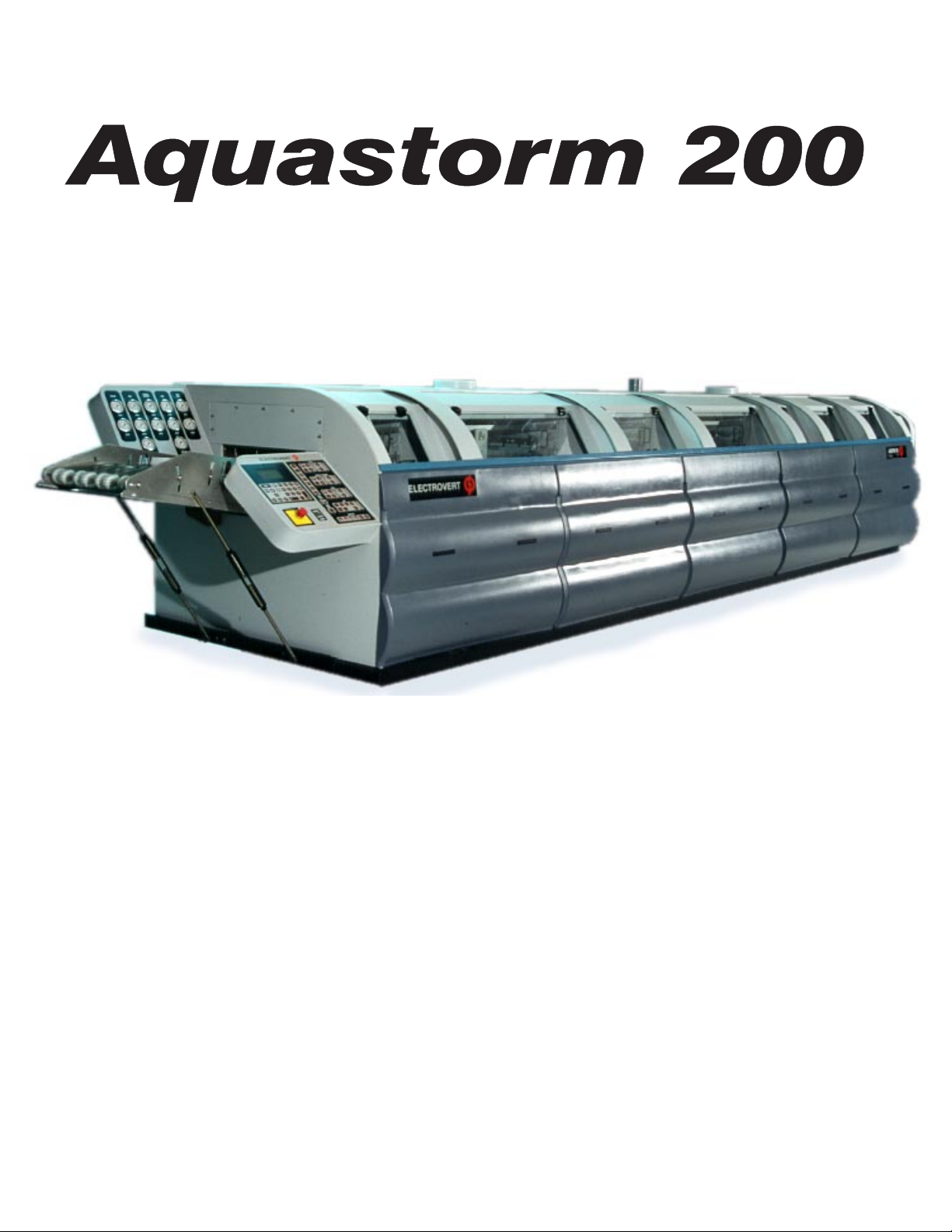
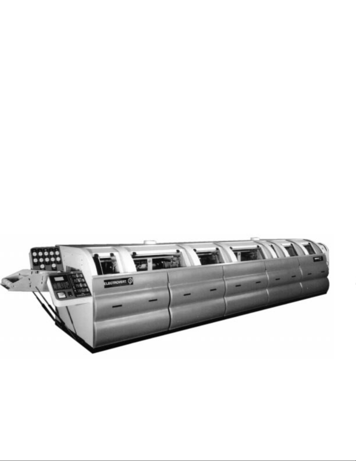
Aquastorm 200
Aqueous Cleaning System
Instruction Manual
Copyright © 1996 Electrovert®
No part of this manual may be reproduced, stored in a retrieval system, or transmitted in any
form or by any means: electronic, mechanical, photocopying, recording, scanning, or otherwise
without the prior written permission of Electrovert.
Published, December 17, 1996
Manual Part Number
2-9316-621-00-0
Text Part Number
2-9316-622-00-0

ii
Aquastorm 200™
INTRODUCTIONINTRODUCTION
INTRODUCTIONINTRODUCTION
INTRODUCTION
Congratulations on your purchase of an Aquastorm 200™ Aqueous Cleaning System. The Aquastorm 200™ is a powerful,
efficient aqueous cleaner designed for the removal of contaminated fluids and particles left behind from wave soldering and/
or reflow processes on complex surface mount and mixed technology PWAs. Each section of the Aquastorm 200™ has
been carefully integrated and balanced to achieve the best cleaning and drying capability for its size and cost, available in the
industry.
The purpose of this manual is to help obtain the greatest possible return on your investment. It is suggested that new
operators study the applicable sections of this manual thoroughly before operating the equipment. It is further suggested
that the manual be used as a reference by maintenance personnel and as a text for training of new maintenance personnel.
This manual includes operating instructions for this equipment available at the time this manual was approved for printing.
Electrovertreservestherighttomakechangesindesignandspecificationsand/ormakeadditionstoorimprovementsinthe
product without imposing any obligations upon itself to install them on previously manufactured products.
Electrovert Sales and Service OfficesElectrovert Sales and Service Offices
Electrovert Sales and Service OfficesElectrovert Sales and Service Offices
Electrovert Sales and Service Offices
Regional Service CentersRegional Service Centers
Regional Service CentersRegional Service Centers
Regional Service Centers
North East Regional Service Center
472 Amherst St. Suite 6
Nashua, NH 03063
Fax: 603-880-8757
Tel: 603-883-2488
South East Regional Service Center
200 Technology Dr.
Alpharetta, GA 30005
Fax: 770-442-1987
Tel: 770-475-6100
North Central Regional Service Center
580-A Tollgate Road
Elgin, IL 60123
Fax: 847-289-3797
Tel: 847-695-5750
North West Regional Service Center
2968 Scott Blvd.
Santa Clara, CA 95054
Fax: 408-727-0672
Tel: 408-727-4650
South West Regional Service Center
1111 W. North Carrier Parkway
Grand Prairie, TX 75050
Fax: 972-606-1700
Tel: 972-606-1900
Electrovert Main OfficesElectrovert Main Offices
Electrovert Main OfficesElectrovert Main Offices
Electrovert Main Offices
Product & Technology Center
Electrovert USA Corp.
1111 W. North Carrier Parkway
Grand Prairie, TX 75050
Fax: 972-606-1700
Tel: 972-606-1900
Technical Service Support Group &
Customer Service Parts Department
Electrovert USA Corp.
P.O. Box 709
Camdenton, MO 65020
Fax: 573-346-6878
Tel: 573-346-3341
Educational Services & Customer Support
Center
580-A Tollgate Road
Elgin, IL 60123
Fax: 847-289-3797
Tel: 847-695-5750
International Service CentersInternational Service Centers
International Service CentersInternational Service Centers
International Service Centers
Northern Europe & U.K.
Electrovert U.K. Ltd.
The Technology Centre
Unit 1, Pincents Kiln Industrial Park
Pincents Kiln
Calcot, Reading
Berks., U.K. RG31 7SO
Fax: 44 11-8-930-1401
Tel: 44 11-8-930-1400
Electrovert Singapore
10 Kian Teck Crescent
Singapore 628876
Fax: 65-861-7337
Tel: 65-861-1661
Japan
Electrovert-Seitec Co., Ltd.
1538 Kanoya-cho
Hachioji City, Tokyo 193 JAPAN
Fax: 81-426-23-8350
Tel: 81-426-23-7722
Northern Europe
Speedline Technologies S.A.R.L.
65 Avenue du General De Gaulle
Immeuble le Promethee
77420 Champs-Sur Marne, France
Fax: 33 160-05-6129
Tel: 33 160-06-8181
Central Europe
Speedline Technologies, Gmbh
Daimlerstrasse 1E D-63303
Dreieich, Germany
Fax: 49 6103-832119
Tel: 49 6103-8320
Speedline Technologies Italy
Via Liguria 2/28
I-20068 Peschiera Borromeo (MI)
Italy
Fax:39- 2 - 5530.8468
Tel: 39- 2 - 5530.8339

iii
Aquastorm 200
ELECTROVERT
TYPE
SER #
ELEC
DATE
VOLT
KVA
PH
HZ
MAX. LINE AMPERAGE
LARGEST MOTOR/LOAD
SHORT CIRCUIT
INTERRUPT CAPACITY
MADE IN U.S.A.
AMP
AMP
AMP
The Serial Tag information is to be filled by the user for Technical Support Purposes. Please have
this information available when contacting Technical Support or when placing parts orders.

iv
Aquastorm 200
Date
Company name: Machine name:
Address: Model number:
Mech. serial #:
Telephone: Elect. serial #:
Facsmile: Item/kit description:
Requested by:
If your machine was retrofitted or modified, please specify retrofit number or description
of modifications.
If the parts you are ordering are described in a quote, please include the quote number.
Parts Order Sheet ELECTROVERT
Please Photocopy this form for further use
Fill out this sheet to order parts/kits for your machine
Part Number Description Quantity

i
DIVISION 1 - OVERVIEW
Table of Contents
SECTION 1 GENERAL ................................................................................................................................... 1-1
1.1 HAZARDS ......................................................................................................................................... 1-1
1.2 Safety Precautions .............................................................................................................................. 1-2
SECTION 2 DESCRIPTION............................................................................................................................ 1-4
2.1 Process Zone Area .............................................................................................................................. 1-4
2.2 Detailed Description............................................................................................................................ 1-5
Cabinet ........................................................................................................................................... 1-5
Plumbing......................................................................................................................................... 1-5
System Controls............................................................................................................................... 1-6
Prewash Section .............................................................................................................................. 1-6
Heated Recirculating Wash Hurricane Section ....................................................................................1-7
Dragout/ Enhanced Chemical Isolation Section ...................................................................................1-8
Heated Recirculating Rinse/ Hurricane Section ..................................................................................1-9
Final Rinse Section ........................................................................................................................ 1-10
Blower Drying Section #1 & #2 ....................................................................................................1-10
Stainless Steel Wire Belt Conveyor ..................................................................................................1-11
Noise Suppression Hood..................................................................................................................1-11
Stainless Steel Pressure Gauges.......................................................................................................1-12
Internal Slide Gate Dampers............................................................................................................1-12
Optional Checkmate™ Hold Down Conveyor .....................................................................................1-13
Optional Photocell Control ..............................................................................................................1-14
Auto Start Timer ........................................................................................................................... 1-14
Optional Detergent Injection System ................................................................................................1-14
Optional Interior Lighting................................................................................................................1-14
Optional Electrosonic™ Airknife ......................................................................................................1-15
Optional Digital pH Monitor ............................................................................................................1-15
Optional Digital Resistivity Monitor..................................................................................................1-15
Optional Utility Sink ...................................................................................................................... 1-15
Optional Convenience Package .........................................................................................................1-16
Angle Adjustable Transition Conveyor ...............................................................................................1-18
2.3 Standard Spray Manifold/nozzle configuration (Basic system) ...............................................................1-19
2.4 Optional Spray Manifold/Nozzle Configuration ....................................................................................1-19
2.5 Dimensions....................................................................................................................................... 1-20
SECTION 3 FACILITIES REQUIREMENTS...................................................................................................1-22
3.1 Water Requirements.......................................................................................................................... 1-22
Final Rinse .................................................................................................................................... 1-22
System Drain................................................................................................................................. 1-22
Fill................................................................................................................................................ 1-22
3.2 Exhaust Requirements ....................................................................................................................... 1-23
3.3 Electrical Requirements..................................................................................................................... 1-24
Reference Schematics .................................................................................................................... 1-24
Power ........................................................................................................................................... 1-24
3.4 Capacities......................................................................................................................................... 1-25
3.5 Specifications ................................................................................................................................... 1-25
-

Aquastorm 200
Overview 1-1
SECTION 1 GENERAL
1.1 HAZARDS
Operation of this equipment involves exposure to potential health hazards.
WARNING Risk of Electric Shock:
Operation of this equipment exposes the operator to situations which may result in electrical
shock if procedures are not properly adhered to. Pay close attention to Warnings of this nature
throughout the context of this manual.
When performing maintenance procedures using ammeters, volt meters or ohm meters,
electrical shock hazard is present. These procedures must be performed only by an authorized
electrician, electrical engineer or service technician familiar with testing live voltage.
WARNING Hot Surfaces/Burn Hazard:
During normal operation this equipment and some of its components operate at temperatures
up to 60-71 oC (140-160 oF). The operator must use extreme caution and wear the
recommended safety garments prior to coming in contact with hot surfaces or components.
Closely follow and adhere to the Warnings in this manual which pertain to hot surfaces.
Use extreme caution when working with or around hot components. Allow hot components to
cool before handling whenever possible.
WARNING Skin Irritation:
When using certain chemicals such as descalers or saponifiers, it is important to follow the
MSDS (Material Safety Data Sheet) guidelines for proper handling and usage. Appropriate
clothing and safety articles must be worn when using descaler solutions. Skin or eye irritation
will occur if not handled properly.

Aquastorm 200
1-2 Overview
1.2 SAFETY PRECAUTIONS
Good housekeeping and cleaning of equipment on a continuously monitored maintenance schedule is extremely
important to the safety and reliability of the equipment's operation.
Electrical work should only be performed by qualified electricians and maintenance personnel.Always shut OFF
Main Power before performing any repairs on electrical circuits.
Prior to applying power for the first time, ensure that the system is properly grounded.
Post "NO SMOKING" signs in the work area and provide measures for enforcement.
Exercise caution when using strong cleaning agents, solvents and other chemicals. Manufacturers' Data provided
(bythechemical manufacturer)contains specificusesand safetyprecautionswhich mustbe thoroughlyunderstood
and strictly adhered to. If in doubt about any caution, contact the manufacturer for clarification.
Avoid prolonged skin contact and inhalation of chemicals and fumes.
Operating this equipment may introduce burn hazards.Avoid contact with all hot surfaces, hot water and steam.
The viewing glass will reach temperatures in excess of 79 oC (175 oF). Extreme caution should be taken to avoid
touching the glass surfaces.Water temperatures will reach and/or exceed 71 oC (160 oF). Steam may escape from
the system cabinet when access windows are removed during operation or for maintenance procedures. Steam
will cause serious burns.Avoid contact with steam.
Protective clothing is required for servicing hot machine components or areas of the machine which come in
contact with chemical applications . Protective clothing includes ANSI (American National Standard Institute)
approve Safety Goggles, NIOSH (National Institute for Occupational Safety and Health) or MSHA (Mine,
Safety and HealthAdministration)Approved Respirator, steel toe safety shoes, high temperature, acid and water
resistant gloves, apron and a long-sleeved garment.
Fumes can be generated from certain saponifiers, defoamers, descalers, and cleaning solvents, during operation.
Precautions must be taken to avoid accumulation of flammable vapors. Whenever harmful fumes are present, a
proper extraction (exhaust) system must be provided. Refer to the manufacturers for information and safety
precautions concerning their products and system exhaust specifications.
Refer to specific Chemical Manufacturers' Material Safety Data Sheets for disposal and/or removal and handling
of waste materials resulting from chemical operating processes.
Under the previously mentioned circumstances, all operators should be provided with an NIOSH or MSHA
Approved Respirator, to provide the operator effective protection from airborne residue resulting from certain
saponifiers, defoamers, descalers, and cleaning solvents.

Aquastorm 200
Overview 1-3
WARNING Warning notices are used in this manual to emphasize
hazardous voltages, high currents, high temperatures or
other conditions that could cause personal injury.
DANGER Danger notices are used in this manual to warn the
operator that DEATH may result if a procedure is omitted
or improperly performed.
CAUTION Caution notices are used to call attention to a situation
that could cause damage to the equipment.
Aquastorm 200
1-4 Overview
SECTION 2 DESCRIPTION
The Aquastorm 200™ Aqueous Cleaning System provides automated, aqueous
cleaning and removal of contaminated fluids and particles from PWAs (Printed
Wiring Assemblies), resulting from wavesoldering and reflow processes, in
the following sequence:
2.1 PROCESS ZONE AREA
(See figure below for zone locations)
1. Prewash - 36 cm (14 inches)
2. Heated Recirculating Wash - 122 cm (48 inches)
3. Drag Out/ Enhanced Chemical Isolation - 91.44 cm (35 inches)
4. Heated Recirculating Rinse - 122 cm (48 inches)
5. Fresh Water Final Rinse - 46 cm (18 inches)
6. Blower Drying Station #1 - 76 cm (30 inches)
7. Blower Drying Station #2 - 76 cm (30 inches)
Optional Additional Drying Stations - (Not pictured)
8. Blower Drying Station #3 - 76 cm (30 inches)
9. Blower Drying Station #4 - 76 cm (30 inches)
1234567
Process Zone Areas of the Aquastorm 200™

Aquastorm 200
Overview 1-5
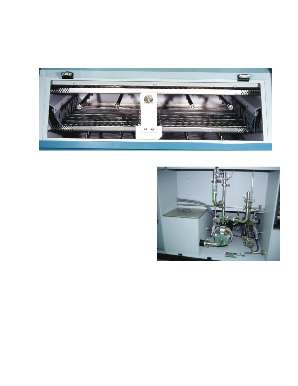
2.2 DETAILED DESCRIPTION
Cabinet
The Aquastorm 200's TM futuristic design is constructed of custom textured gray polypropylene. The removable
front and rear access panels are composed of light weight, molded ABS (Acrylonitrile-Butadiene-Styrene).
Its one piece construction is comprised of 1/2and 1/4inch textured gray polypropylene with triple welded
tanks. The textured gray polypropylene resists scratching and is aesthetically pleasing.
The cabinet's overall gray color, combined with darker gray molded ABS curved front access panels, and an
accent of light blue trim separating the two (2) shades of gray, make the system's appearance an attractive
one to any manufacturing production line.
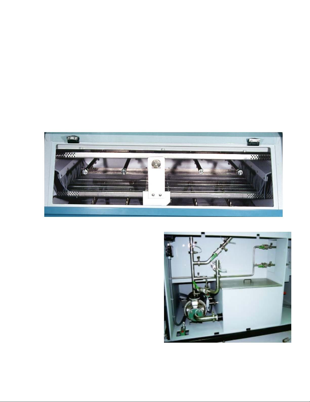
Plumbing
All rear plumbing, including fill and final rinse
inlets, is comprised of 3/4, 1 1/2and 2.0 inch
orbitally welded, tubular stainless steel pipe with
"Kwik Clamps". Smooth transition, orbitally
welded stainless steel plumbing minimizes
pressure drops and eliminates leaks.
"Kwik Clamps" with TeflonTM O-rings provide for
easy maintenance and field upgrades. Both can
be performed with unprecedented ease.
All internal upper and lower spray manifold
plumbingis stainlesssteel,reducing the corrosion
and maintenance factors normally introduced
with CPVC type spray manifold systems.
All drain lines are 1 1/2inch CPVC with brass
solenoid drain valves. Stainless steel solenoid
valves are optional.

Aquastorm 200
1-6 Overview
System Controls
Aquastorm 200™ operator controls are
incorporated into a single custom control panel
at the entrance end of the system. All system
control functions are via a membrane touch pad
panel with graphic symbols, a multi-line LCD
(Liquid Crystal Display) with membrane keypad,
and an internal 486 computer with fiber optic
interface connections. Indicator lights provide
system status of water levels, temperature levels,
operatingindication of pumps,blowers,fill/ drain
solenoids, radiant heaters, and conveyor.
Prewash Section
The Prewash section is 36 cm (14 inches) long
consisting of two (2) upper spray manifolds and
two (2) lower spray manifolds. Power cascade is
from the Recirculating Wash tank. Prewash can
be directed to drain or to cascade to recirculating
wash.
NOTE When operating the prewash
direct to drain, the prewash
operating pressure must be set
lower than the pressure at the
finalrinse,to preventexcesswater
consumption in the wash section.
Aquastorm 200
Overview 1-7
Anoptional HurricaneJetTM performancekit may
be configured which includes a 10 HP pump in
lieu of the standard 5 HP pump. The Hurricane
JetTM manifold is configured between the
standard four (4) upper spray manifolds.
The water level in the wash tank is monitored by
means of liquid level float switches. If the tank
fluid level falls below the low level float switch,
the tank heaters shut off and trip the tank level
alarm indicator on the front control panel along
with an audible alarm.
Tank filling is automatic via the fill solenoid,
activated by the low and/or operating liquid level
float switch(es) in the wash tank. When the
system is initially activated and the tank is empty,
the fill solenoid activates to fill the system tanks.
During normal operation, if the water level falls
below normal operating level, the fill solenoid
activates to fill the tank.
Heated Recirculating Wash
Hurricane Section
The Recirculating Wash section is 122 cm (48
inches) long consisting of four (4) upper spray
manifolds and four (4) lower spray manifolds,
powered by a 5 HP pump (standard
configuration). A 303 liter (80 gal.) tank is
standard with two (2) 16 kw immersion heaters.
Temperatures are displayed via the LCD (Liquid
Crystal Display). The computer continually
monitors and corrects the temperature in the
wash tank by means of a thermocouple device. If
the temperature exceeds 82 oC (180 oF), the
tank's high temperature alarm indicator
illuminates, the audible alarm sounds and the
tank heaters shut off.
Aquastorm 200
1-8 Overview
Dragout/ Enhanced Chemical
Isolation Section
The Drag Out/ Enhanced chemical isolation
section is 30.5 cm (36 inches) long, and may be
configured as one (1) of four (4) different
configurations:
1Standard Chemical Isolation - standard
configuration is without airknives or spray
manifolds. Excess water drips from
product as it passes through this section.
This allows fewer contaminants to be
carried over to the rinse section.
NOTE When saponifier is being added to
thewashsection and therinsewater
is recirculating, standard
configuration of the enhanced
chemical isolation will not provide
adequate separation.
2Level 1 Chemical Isolation - this level may
be configured as an option with a 7.5 HP
Turbine blower and three (3) tubular
stainless steel airknives. The blower
delivers air through two (2) upper and one
(1) lower air knife.
Blower Air removes and squeegees excess
water containing contaminants from the
product prior to entering the
Recirculating Rinse section of the
Aquastorm 200™. Excess water removed
via the first set of airknives is routed back
to the wash section. This helps in
preventing loss of saponifier as well as
reducing the risk of cross contamination
between cleaning sections.
3Level 2 Chemical Isolation - incorporates
the blower configuration in Level 1, and
adds two (2) stainless steel, one (1) upper
and one (2) lower, spray manifolds. The
spray manifolds are positioned between
the two (2) sets of airknives. The spray
bar water supply is via an exeternal feed,
customer supplied source. The spray bars
provide low volume spray to enhance the
removal of remaining saponifier solutions
remaining on the product. This
configuration of chemical isolation is
routed directly to drain, to eliminate cross
contamination.
4Level 3 Enhanced Chemical Isolation -
includes both level 1 and 2 configurations,
but is supplied with optional on-board, 95
liter (25 gallon) tank in lieu of an external
water source plumbing configuration.
A 1/8Hp internal recirculation pump
powers the spray manifolds. The tank is
also configured with one (1) 18 kW
immersion heater, auto fill, tank liquid
level floats, and rinse to chemical isolation
cascade. Level 3 provides increased
isolation while conserving water usage.
Aquastorm 200
Overview 1-9
Heated Recirculating Rinse/ Hurricane Section
The Recirculating Rinse section is 122 cm (48 inches) long consisting of four (4) upper spray manifolds and
four (4) lower spray manifolds, powered by a 5 HP pump (standard configuration). A 189 liter (50 gal.)
tank is standard with two (2) 16 kw immersion heaters.Temperatures are displayed via the LCD. The
computer continually monitors and corrects the temperature in the rinse tank by means of a thermocouple
device. If the temperature exceeds 82 oC (180 oF), the tank high temperature alarm indicator illuminates,
the audible alarm sounds and the tank heater shuts off.
Anoptional HurricaneJetTM performancekit may
be configured to include a 10 HP pump in lieu
ofthe standard 5HP pump. TheHurricaneJetTM
manifold is configured between the standard four
(4) upper spray manifolds.
The water level in the rinse tank is monitored by
means of liquid level float switches. If the tank
fluid level falls below the low level float switch,
the tank heaters shut off and trip the tank level
alarm indicator on the front control panel along
with an audible alarm.
Tank filling is automatic via the fill solenoid,
activated by the low and/or operating liquid level
float switch(es) in the rinse tank. When the
system is initially activated and the tank is empty,
the fill solenoid activates to fill the system tanks.
During normal operation, if the water level falls
below normal operating level, the fill solenoid
activates to fill the tank.
The recirculating rinse tank is configured with a
cascade pipe to the recirculating wash tank. Flow
through the cascade pipe, from rinse to wash, is
controlled via a ball valve. O/A (Organic Acid)
or water soluble applications should be run with
the valve in the open position. Rosin or saponifier
applications should be run with the valve in the
closedposition, not permittingcascadingto occur.
If the system is configured with an on-board tank
for Enhanced Chemical Isolation (Level 3), a
cascade pipe from the recirculating rinse tank to
the Chemical Isolation tank is supplied as well.
The valve supplied on this cascade pipe should
remain closed for O/A applications. When
running saponifier processes, the ball valve on
the cascade pipe to the Chemical Isolation tank
should be open slightly. This is to prevent the
chemical isolation tank from loading up with
excess saponifier. The amount this valve is open
or closed is dependent upon the type of saponifer
as well as the product mix or product
configuration.
Aquastorm 200
1-10 Overview
Final Rinse Section
The Final Rinse section is 46 cm (18 inches)
longconsisting oftwo(2) upperand two (2)lower
stainless steel spray manifolds. Water is supplied
via a fresh water inlet (preferably heated DI
{deionized} water) from the facility water supply.
Final rinse water cascades into the recirculating
rinse tank.
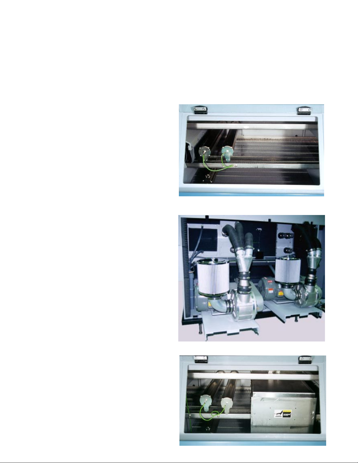
Blower Drying Section #1 & #2
Both Blower Drying section #1 and #2 are each
76 cm (30 inches) long. Each section is
configured standard with two (2) upper, height
adjustable and one (1) lower, fixed, stainless steel
airknives. Air is delivered through the airknives
using a high velocity, high volume turbine blower.
The blower is configured as 7.5 Hp standard or
as 10 or 15 HP optionally (dryer section 1 only),
in lieu of the 7.5 HP blower. This ensures
maximum drying efficiency prior to product
exiting the system. Note that 15 HP blower
applications are usually for customers with large,
heavy boards. 15 HP blower configurations may
cause smaller boards to become airborne or to
become lodged in the conveyor system.
Each Blower Drying section is configured with
thermocouple sensors for temperature readout
only, via the LCD.
Blower Dryer section #2 may be configured
optionally with a radiant heater. The radiant
heater incorporates two (2) 1800 watt radiant
heater panels. One (1) 1800 watt upper radiant
panel,and one (1)1800watt lowerradiantpanel;
3600 watts total. Control and readout are
provided by a thermocouple sensor and the
computer system with digital readout via LCD.
NOTE Temperature readout is replaced
with temperature control when
this option is configured.

Aquastorm 200
Overview 1-11
Stainless Steel Wire Belt
Conveyor
The stainless steel wire belt conveyor is a
0.95 cm (3/8inch) pitch 50.8 cm (20 inch)
wide speed controlled wire mesh belt. The
conveyor belt transports product for
cleaning and drying in a single pass
through the Aquastorm 200™ system.
Note that the usable conveyor width is
limited to 46 cm (18 inches).
Optionally, the wire belt conveyor may be
configured with a 61 cm (24 inch) wide
belt; 56 cm (22 inch usable) width.
Noise Suppression Hood
The Noise Suppression Hood is standard with
the Aquastorm 200™. This feature incorporates
a 46 cm (18 inches) conveyor extension for easy
removal of product, and extends 15.24 cm (6)
inches past the exit end of the system's cabinet.
The noise level is equal to or better than 80 dBA
(maximum) measured 1 meter (3 feet) above the
floor and 1 meter (3 feet) from the Aquastorm
200™ enclosure.

Aquastorm 200
1-12 Overview
Stainless Steel Pressure
Gauges
The Aquastorm 200™ is configured standard
withfrontmountedstainless steel pressure gauges
for all wet sections. The gauges are visible from
thecustom operatorcontrol panel atthe entrance
end of the system for easy viewing and
monitoring.
Internal Slide Gate Dampers
Internal slide gate dampers are designed into the
one piece construction of the internal portion of
the cabinet to permit fine tuning of the system's
exhaust flow. The slide gate dampers are
completely adjustable and are included in the
Prewash,Dragout/Enhanced ChemicalIsolation,
Blower Dryer Section #1 and Blower Dryer
Section#2. These dampersmaybeadjustedfrom
either the front of the system, through the access
windows, or from the rear of the system at the
bulkhead wall. Once the dampers have been
adjusted for proper exhaust flow, the damper
positions may be set by simply tightening a thumb
screw.

Aquastorm 200
Overview 1-13
Optional Checkmate™
Hold Down Conveyor
The Checkmate™ Conveyor is designed for
product that can normally be jostled, elevated or
even flipped during cleaning processes.
The optional Checkmate™ Conveyor may be
configured with a 50.8 cm (20 inch) or 61 cm
(24 inch) wide conveyor. Note that the usable
widths directly correlate to those of the standard
conveyorbelt system.TheCheckmate™ Conveyor
consists of a double conveyor system that gently
restrains any sized product, through all washing,
rinsing and drying processes.
At the entrance end of the system, an upper
conveyoris gentlylaid across the topof the circuit
boards as they travel on the lower conveyor. Both
the upper and lower conveyors are synchronized
to operate at the same speed through the entire
system. Product is protected from lateral and
vertical movement.
An additional safety feature is provided using an
optical sensor at the exit end of the conveyor
that searches for entangled boards and initiates
system shutdown along with alarms.
Entrance End View With Maintenance Panel Removed
Photocell
Exit End View with Sound Enclosure Open

Aquastorm 200
1-14 Overview
Optional Photocell Control
The photocell provides automatic standby mode
via photo-eye sensor. The photo sensor is to be
used in conjunction with the optional Angle
Adjustable Transition Conveyor or optionally
withoutthe transitionconveyor. Thephoto sensor
and reflector are mounted on the inlet conveyor
or on the entrance end of the conveyor system,
dependingon thesystemconfiguration. Photocell
operation sequentially starts pumps, blowers and
final rinse as product passes the photocell. When
product has exited the conveyor (based on a fixed
time and distance), photocell operation stops
pumps, blowers and final rinse water. The
conveyorremainsin operation toadvance procuct
into the system. The system may be configured
to allow the blower to remain on with the
conveyor.
Auto Start Timer
By auto enabling the system fill solenoid and the
Wash and Rinse tank immersion heaters prior
to system start up, the Auto Start Timer
eliminates delays in production while the
Aquastorm 200™ system power is active.
Start and stop times for each day of the week
may be configured using the timer function
software and the LCD interface keypad.
Optional Detergent Injection
System
The Automatic Detergent Feed system provides
automatic feed with a calculated mixture of
saponifier or detergent from an internal 57 liter
(15 gallon) reservoir located just inside the rear
prewash section, into the wash section plumbing.
Anytime the fill solenoid is activated to add water
to the wash section, saponifier or detergent is
automatically injected into the wash plumbing as
water passes the venturi injector.
Optional Interior Lighting
The Aquastorm 200™ system may be configured
with three (3), 40 watt, 110 VAC, fluorescent
light fixtures which provide maximum viewing
capability as well as cost efficient lighting. The
interior lighting option permits the operator to
observe the entire cleaning process as product
passes through each stage of the system.

Aquastorm 200
Overview 1-15
Optional Electrosonic ™
Airknife
Theoptional Electrosonic™ Airknife replacesthe
standard airknife system in the dryer sections of
the Aquastorm 200™. The Electrosonic™
Airknife's unique teardrop design maximizes air
velocity as the air is forced through the airknife
slot. The slot is adjustable for optimization
depending on blower configuration. All
Electrosonic™ Airknives are adjusted according
to voltage, Hz, and blower size. The result, "a
sheet of air is produced", much less diffuse than
that of cylindrical airknives. This "sheet of air" is
also much less sensitive to the height from the
product. Based on residual weight gain testing
performed on a variety of boards run at 2, 4,
and 6 feet per minute, drying performance with
the Electrosonic™ Airknifes system was better
by 25 - 68% than that of the traditional
cylindrical airknife systems.
Optional Digital pH Monitor
Theoptional pH Monitorprovidesadigital display
via the LCD, of pH levels ranging from 0 - 14
for water in the wash tank. Displays are read in
millivolts (mV), degrees Celsius (oC) and pH.
Input to the monitor is supplied by means of a
pH sensor which is mounted through the wall of
the wash tank for easy accessibility and
maintenance. High and low process alarms are
adjustable via the LCD and interface keypad.
Optional Digital Resistivity
Monitor
The optional Resistivity Monitor provides
accurate digital display of resistivity levels with a
resistivity range of 0 - 18 Meg Ohms (M W) for
incoming water in the Final Rinse.
Optionaldigital resistivity isdisplayedviathe LCD
and has user adjustable high and low alarms.
Optional Utility Sink
The optional utility sink is located at the rear
exit end of the system, just behind the exit end
sound enclosure. The utility sink includes hookup
from the incoming fill line. A single goose neck
faucet and spray wand are supplied with the sink
option for easy cleanup. The sink drain is tied
into the system's main drain plumbing.
Electrosonic™ Airknife
Utility Sink with Goosenek Faucet and Spray Wand
Table of contents


