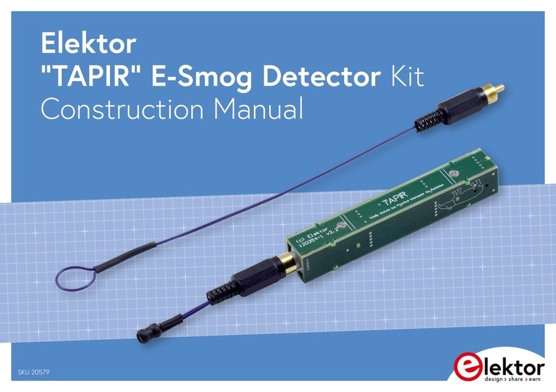
Elektor TAPIR Instructions for use

1
Elektor Construction Guide
TAPIR
The TAPIR is a three-dimensional assembly.
To ensure good access to all soldering points,
we recommend assembling the kit
exactly according to the described sequence.

2
Kit Contents
The ollowing components should be present in the kit:
-1 PCB panel
-1 headset (ear buds)
-1 plastic bag with all electronic components
-1 length o wire (approximately 40 cm)
The plastic bag should contain the ollowing items:
-2 small bags with small parts
-1 coil
-2 Cinch plugs
-1 Cinch panel-mount connector
The small bags should contain the ollowing components:
Bag 1:
-1 resistor 1 kΩ (R5)
-2 resistors 10 kΩ (R2, R3)
-1 transistor BSR17 (T1)
-2 transistors BC847B (T2, T3)
-1 capacitor 10 nF (C1)
-2 stando s M2x6
-2 screws M2x6
Bag 2:
-2 resistors 100 kΩ (R1, R4)
-3 capacitors 10 µF (C2, C3, C4)
-1 diode BAT54S (D1)
-1 switch
-1 3.5 mm audio jack
-1 spring or battery
Required Items
The ollowing items are required or the proper assembly o this kit:
- A well lit and tidy work sur ace
- The TAPIR kit
- A soldering iron or soldering station with a ine tip
- Tweezers or placing small SMDs on the board
- Resin-core solder with a maximum diameter o 0.5 mm (0.02 inch)
- A small drill bit or countersinking the cover screws
- One AAA battery
- A length o heat-shrink tubing or electrical tape
- I necessary, a magni ying glass or checking
component markings and solder joints
- A coping saw and a ile or Dremel tool as necessary
- Clamping tweezers as necessary

3
Tips
•When breaking the individual PCBs ree rom the panel, be care ul to avoid
damage to the tabs or itting PCBs 1, 3, 5, 6 and 7 to the component PCB.
We recommend using a coping saw to cut these PCBs ree rom the panel.
PCBs 2 and 4 can be broken ree by hand. The tabs on these PCBs must be
removed (e.g. by iling them o ). However, do not do this until
instructed to do so.
•There are several solder connections between the various PCBs. Be sure to
make these connections during assembly.
•Apply solder sparingly, especially on the board itted with the headset
connector. Proper assembly o the PCBs may be di icult i the solder layer
is too thick.
•The antenna is electrically connected to the circuit. To avoid the risk o
electrical shock, always ensure that the antenna is properly insulated.
oldering MDs
We recommend soldering the SMD components in the TAPIR kit one at a time.
It’s easy to get them con used, and they are so small that they can easily get
lost i they are loose on the work sur ace.
Start by tinning one o the solder pads. Hold the solder against the pad and
brie ly touch it with the tip o the soldering iron as close to the pad as possible,
so that the pad is covered by a thin layer o solder. Then place the component in
position. This is best done with tweezers. Secure the component with the
tweezers i necessary, and then shortly touch the tinned solder pad with the tip
o the soldering iron. The solder will re low and orm a bond between the
component and the solder pad. I the component is properly positioned, the rest
o the component leads can be then soldered by holding the solder against the
solder pad and the component lead and brie ly heating the joint. Short soldering
times produce clean and tidy joints.

4
The PCBs
The TAPIR is assembled rom seven small PCBs supplied as a PCB panel. They
collectively orm the enclosure or the circuit. Each o these PCBs is numbered:
1. Top piece
2. Side piece with switch
3. Bottom piece with components
4. Side piece with headset connector
5. Negative battery connection
6. Positive battery connection
7. End piece

5
Assembly
Start by soldering the switch onto PCB 2 and the panel-
mount connector or the headset onto PCB 4 (apply solder
sparingly). Then remove these two PCBs rom the PCB
panel and ile the tabs o .
Next, it the ollowing components on PCB 3 using the previously
described soldering method:
1. C3 (10 µF; no marking, large SMD)
2. R1 & R4 (100 kΩ; marking 1003)
3. R2 & R3 (100 kΩ; marking 1002)
4. R5 (1 kΩ; marking 1001)
5. C1 (10 nF; no marking, small SMD)
6. T1 (BSR17; marking U92)
7. T2 & T3 (BC847, marking 1FW)
Now check the circuit or proper operation be ore
continuing with assembly. This is important because any
mistakes at this stage will be very di icult or impossible
to correct later on.
Temporarily connect a 1.5 V supply voltage to the points indicated below.
1
2
3
5
4
6

6
Measure the DC voltage at the upper solder pad o C4
(which is connected to T3 and R4). It should be
somewhere between 0.5 V and 1.0 V. I it is not, check
all solder joints or proper contact and check that all
components have been itted in the right places.
I everything is OK, the inal three
components can now be itted:
8. D1 (BAT54; marking WV4)
9. C2 & C4 (10 µF; no marking, large
SMD)
Now remove PCB 3 rom the panel, taking care to avoid damage to the tabs.
Then solder the Cinch panel-mount connector onto the PCB
( irst straighten the two ground tabs).
Remove PCB 5 rom the panel and lay PCB 3
on the bench with the Cinch connector acing
away rom you. Place PCB 5 in the proper
position on PCB 3 and perpendicular to PCB 3,
with the marking M2×6 acing the Cinch
connector. For now, solder only the pad at the bottom right.
Remove PCB 6 rom the panel and it it perpendicular to PCB 3
with the marking M2×6 acing you. For now, solder only the pad at
the bottom right.
Remove PCB 7 rom the panel and it it perpendicular to PCB 3.
The proper orientation is clearly indicated by the solder pads.
Solder all three pads.
Take PCB 4 (with the headset connector) and insert it care ully into
the rear piece and down onto the bottom piece, so that the tabs o
PCB 5 and PCB 6 it into the recesses in the side pieces. Press the
PCBs irmly together and solder them in place, starting at the
middle. While doing this, regularly check that the PCBs it closely
together at the bottom – at this point it’s still possible to make
corrections.
Now solder the joints between PCBs 3, 4 and 5 and between
PCBs 3, 4 and 6. Be sure to solder the joint between PCBs 3 and 4
at the bottom near the headset connector. I the tip o your
10
7
8
9
11

7
soldering iron is too thick or proper access to these joints, you can use a piece
o solid wire to ‘extend’ the tip. Place the TAPIR on the bench with PCB 4 acing
down and solder the Cinch panel mount connector and PCBs 5, 6 and 7 to PCB 4.
Next it PCB 2 in the same way as PCB 4. The tabs o PCBs 5 and 6 must it
precisely in the notches. Press everything irmly together and solder the Cinch
connector end and the switch end. Check once again that everything is properly
mated and correct this i necessary. I everything is as it should be, solder the
joints between PCBs 2, 3 and 6 and between PCBs 2, 3 and 6.
Place the TAPIR on the bench with PCB 2 acing down and solder the joints between
PCBs 5, 6 and 7 and PCB 2. Check that all o the solder joints have been soldered
and no short circuits are ormed, especially where PCB 2 and 6 meet.
Finally, solder the two M2x6 stando s at the indicated locations on PCBs 5 and 6.
Ensure that they are lush against the board and precisely in the middle. Hold
them in place with clamping tweezers i necessary. I you have a steady hand,
you can also use a screw threaded into the stando .
13
14
15
16
12

8
Remove PCB 1, countersink the mounting holes with a sharp drill bit, and check
that the cover its properly and can be screwed in place. Now it the small spring
and then insert the battery as shown on the PCB. The spring can be soldered in
place i necessary. Now you can place the lid on the TAPIR and screw it tight.
Your TAPIR is ready or use.
17

9
The antennas
Now you need to make two antennas, each o which is suitable or a particular
type o ield: an E- ield antenna or sensing electrical ields and an H- ield
antenna or sensing magnetic ields.
Start with the E- ield antenna. All you need or this is a length o
solid insulated wire. Cut the wire included in the kit in the middle to
obtain two pieces approximately 25 cm long. Take one o these and
orm a loop in one end. Cover the tip o the wire at this point with a
piece o heat-shrink tubing or electrical tape (see photo). This
insulates the antenna, so that you can easily use the loop to sni or
noise on a circuit board.
At the other end o the wire, strip o approximately 3 mm o the
insulation and slide the Cinch connector shell over the wire. Solder
the wire to the centre pin o the Cinch connector. Screw the
connector together and straighten the antenna. The antenna is now inished.
Next comes the H- ield antenna. For this you will use the coil. Trim the leads o
the coil to approximately 4 mm. Cut two lengths o wire approximately 5 cm long
and strip their ends. Solder one end o each wire to the Cinch connector and
screw the connector together. I you are using heat-shrink tubing, slide a piece
o tubing over each wire. Then solder the wires to the coil leads (the polarity
does not matter) and insulate the bare wire ends and coil leads. The H- ield
antenna is now ready or use.
Bear in mind that when you hold the TAPIR in your hand, your body orms part
o the antenna, which may increase the audible hum level.
Other manuals for TAPIR
1
Table of contents
Other Elektor Security Sensor manuals
Popular Security Sensor manuals by other brands

Conrad Electronic
Conrad Electronic FS20 PIRI-2 operating instructions
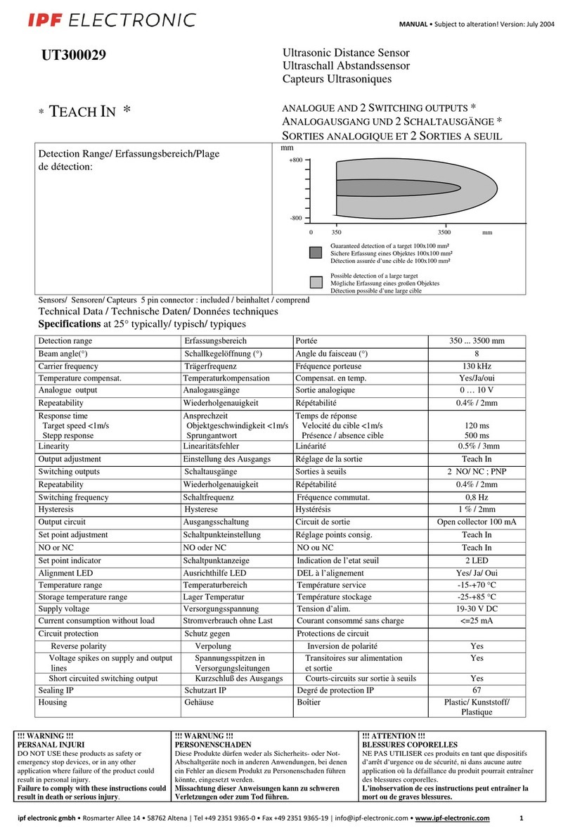
ipf electronic
ipf electronic UT300029 manual
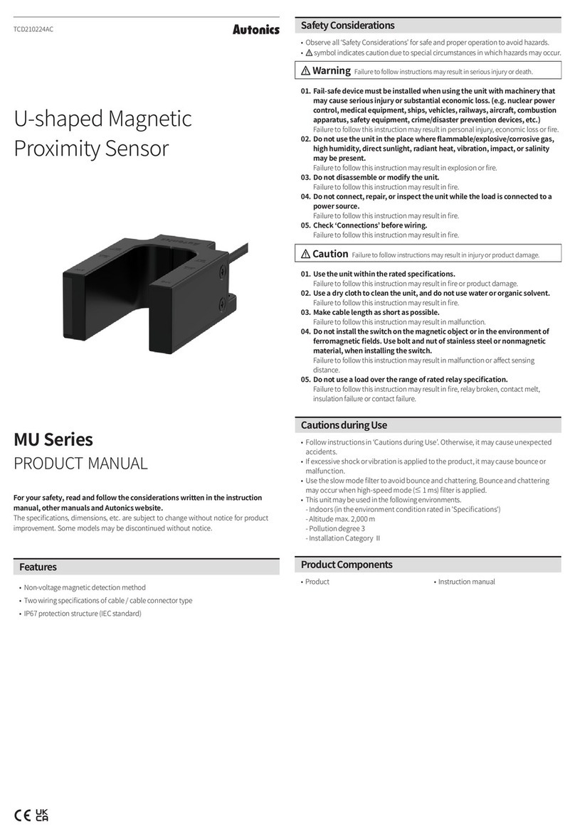
Autonics
Autonics MU Series product manual
DAINESE
DAINESE D-AIR STREET SMART CHEST Series INFORMATIVE NOTE
heddier electronic
heddier electronic Human Detector Flex instruction manual

Dräger
Dräger X-am 5100 Technical manual
