1/9
CONTENTS
Technical data sheet: S000105459EN-2 Updated: 25/02/2021 Created: 05/12/2018
128, av. du Maréchal-de-Lattre-de-Tassigny - 87045 LIMOGES Cedex
Tel: +33(0)5 55 06 87 87 Fax: +33(0)5 55 06 88 88
www.legrand.com
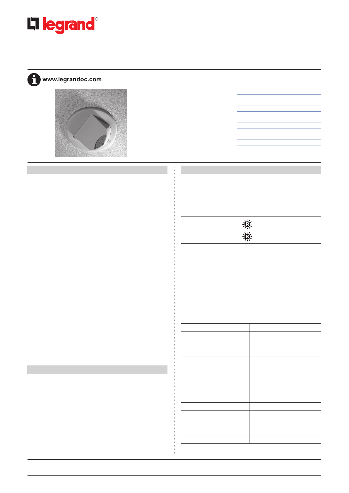
Microwave detector - DALI/DSI dimming Cat. No(s): 0 489 55/56/57
CONTENTS Page
1. Use .....................................1
2. Technical characteristics .................1
3. Dimensions .............................2
4. Connection .............................2
5. Installation ..............................4
6. Operation ...............................4
7. Parameter setting .......................5
8. Troubleshooting ........................8
9. Performance ............................9
10. Care ....................................9
11. Standards ...............................9
1. USE
This microwave presence detector provides automatic control of
lighting loads with optional manual control.
It detects movement using a highly sensitive microwave detector.
Thisworks by emitting low-power microwave signals and measuring
the reflections as the signals bounce off moving objects.
Output channel 1 comprises a mains voltage relay capable of simple
on/off switching, while output channel 2 provides dimmable control of
either DALI or DSI type ballasts and turns the load on. When an area is
no longer occupied, the load will switch off after an adjustable timeout
period.
These units come complete with accessories allowing flush mounting in
suspended ceilings or surface mounting on ceilings, or side mounting
on a luminaire.
The unit can turn lights on when a room is occupied and off when
the room is empty. Optional settings allow lights to be turned off in
response to ambient daylight.
The flexibility of having two output channels and two switch inputs
allows the following example scenarios:
− Dimming an outside row of luminaires whilst internal fittings
are switched
− Providing absence detection for two separate channels
− Installing a maintained illuminance system with manual
override controls for dimming
This detector has an adjustable sensor head that allows the detection
area to be optimised for the application.
All functionality is fully programmable using an infrared configurator.
2. TECHNICAL CHARACTERISTICS
Microwave sensor
Detects movement within the unit’s detection range, allowing load
control in response to changes in occupancy.
IR receiver
Receives control and programming commands from the infrared
configurator.
Walk test LED active When movement is detected
Valid setting received
2. TECHNICAL CHARACTERISTICS CONTINUED
Light level sensor
Measures the overall Lux level in the detection area.
LED status
The LED flashes red to indicate the following:
Power input & switched output connector (channel 1)
Used to connect mains power to the unit and to connect a switched
load
Dimmable control output connector (channel 2)
Used to connect DALI/DSI controllable ballasts for dimmable loads.
Switch input connector
Two input terminals can be used to manually override the dimming
levels and override the lights on or off.
Dimensions See dimensions section
Weight 0.15 kg
Power supply 230 VAC +/-10%
Frequency 50 Hz
Power consumption ON 1500 mW, OFF 961 mW
Terminal capacity 1.5 mm2
Dimming outputs Basic insulation only. Although
low voltage, this is not a SELV
output and should be treated as
if it were mains voltage. Use mains
rated wiring.
Operating temperature -10°C to +50°C
Operating humidity 5 to 95% non-condensing
Material Flame-retardant ABS and PC/ABS
Type Class 2
Protection class IP40


