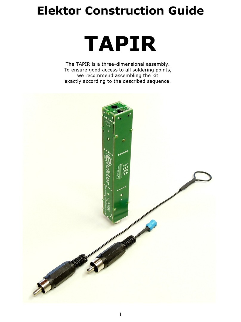
Elektor TAPIR Instructions for use

Elektor
“TAPIR” E-Smog Detector Kit
Construction Manual
SKU 20579

Elektor “TAPIR” E-Smog Tester Kit | Construction Manual
Elektor
“TAPIR” E-Smog Detector Kit
Construction Manual
V2.2 – July 13, 2023, © Elektor International Media b.v.
The TAPIR is a three-dimensional assembly with PCBs for the 6 enclosure sides.
To ensure easy access to all solder points during assembly, be sure to assemble
the kit exactly according to the sequence described.
Publishers’ Notice: The latest version of the Construction Manual of the
“TAPIR” E-Smog Detector Kit supplied by Elektor is available as a pdf file at:
www.elektor.com/.....
2/15

Elektor “TAPIR” E-Smog Tester Kit | Construction Manual
Table of Contents
Section Page
1 – Kit Contents 4
2 – Required Items 5
3 – Tips 5
4 – The Panel 6
5 – Assembly 7
6 – The Antennas 11
7 – Bill of Materials 13
8 – Web Links 13
9 – Schematic and PCB Layout 14
Notice
This document is complementary to the information contained in:
1. the article “TAPIR Snis it Out!” published in Elektor Magazine edition
7&8 2012;
2. the engineering background, reader queries, and related discussions
posted on the Elektor Labs website.
Web Links to these publications may be found in Section 8.
Disclaimer and Copyright Notice
The circuit(s) described in the manual are for domestic and educational
use only. All drawings, photographs, PCB layouts, and texts are copyright
Elektor International Media b.v. and may not be reproduced, transmitted,
or stored in any form in whole or in part without the prior written consent
from the Publisher. Patent protection may exist in respect of circuits and
devices described here. The Publisher does not accept responsibility
for failing to identify such patent(s) or other protection. The Publisher
also denies any responsibility for the safe and proper function of reader-
assembled projects based upon or from schematics or information
published in or in relation to this Manual. E & O. E.
Published by Elektor International Media b.v.,
PO Box 11, NL-6114-JG, Susteren, The Netherlands.
www.elektor.com; www.elektormagazine.com.
3/15

Elektor “TAPIR” E-Smog Tester Kit | Construction Manual
1 – Kit Contents
Figure 1 below shows the components that should be present in the kit
upon opening the box.
Figure 1. Kit contents, as received.
Check for the contents to consist of:
› 1 PCB panel
› 1 headset (ear buds)
› 1 wire piece (length approx. 50 cm)
› 1 piece heat shrink tubing (length approx. 10 cm)
› 1 coil (inductor)
› 2 Cinch (RCA) plugs
› 1 Cinch (RCA) PCB-mount connector
› 1 resistor, 1 kΩ (R5)
› 2 resistors, 10 kΩ (R2, R3)
› 1 transistor, MMBT3904LT3G (T1)
› 2 transistors, BC847B (T2, T3)
› 1 capacitor, 10 nF (C1)
› 2 standos, M2x6
› 2 screws, M2x6
› 2 resistors, 100 kΩ (R1, R4)
› 3 capacitors, 10 µF (C2, C3, C4)
› 1 diode, BAT54S (D1)
› 1 switch
› 1 3.5-mm audio jack
› 1 spring for battery
4/15

Elektor “TAPIR” E-Smog Tester Kit | Construction Manual
2 – Required Items
Figure 2. Some of the items and tools required to assemble the TAPIR kit.
The following items are required for the proper assembly of this kit:
› A well lit and tidy work surface
› The TAPIR kit as supplied by Elektor
› A soldering iron or soldering station with a fine tip
› Tweezers for placing small SMDs on the board
› Resin-core solder with a maximum diameter of 0.5 mm (0.02 inch),
0.35 mm recommended
› Hand-operated countersink or a small drill bit for countersinking the
cover screws
› One 1.5 V AAA-size battery
› If necessary, a magnifying glass for checking component markings and
solder joints
› A coping saw and a file or Dremel tool as necessary
› Clamping tweezers as necessary
3 – Tips
› When breaking the individual PCBs free from the supplied panel, be
careful to avoid damage to the tabs intended for fitting PCBs 1, 3, 5, 6
and 7 to the component PCB. We recommend using a coping saw to
cut these PCBs free from the panel. PCBs 2 and 4 can be broken free
by hand. The tabs on these PCBs must be removed (e.g., by filing them
o). However, do not do this until instructed to do so.
› There are several solder connections between the various PCBs. Be
sure to make these connections during assembly.
› Apply solder sparingly, especially on the board fitted with the headset
connector. Proper assembly of the PCBs may be diicult if the solder
layer is too thick.
› The antenna is electrically connected to the circuit. To avoid the risk of
electrical shock, always ensure that the antenna is properly insulated.
5/15

Elektor “TAPIR” E-Smog Tester Kit | Construction Manual
Soldering SMDs
We recommend soldering the
SMD components in the TAPIR
kit one at a time. Due to their
small size, they are easily mixed
up, mislaid, or even lost when
“strewn” on the work surface.
Start by tinning one of the solder
pads. Hold the solder against
the pad and briefly touch it with
the tip of the soldering iron as
close as possible to the pad, so
that the pad is covered by a thin
layer of solder. Then place the
component in position. This is
best done with tweezers. Secure
the component with the tweezers
if necessary, and then briefly
touch the tinned solder pad with
the tip of the soldering iron. The
solder will reflow and form a bond
between the component and
the solder pad. If the component
is properly positioned, the rest
of the component leads can be
then soldered by holding the
solder against the solder pad and
the component lead and briefly
heating the joint. In general, short
soldering times produce clean
and tidy joints.
4 – The Panel
Top view and bottom view of the breakout panel holding the 7 PCBs.
Figure 6. Top view of PCB breakout Panel 120354 v2.2 for the TAPIR E-Smog Detector.
Figure 3. Example: one pad of SMD transistor
T1 soldered.
Figure 4. One lead of T1 soldered to the PCB.
Figure 5. All three leads of T1 soldered.
6/15

Elektor “TAPIR” E-Smog Tester Kit | Construction Manual
Figure 7. Bottom view of PCB breakout Panel 120354-1 v2.2
for the TAPIR E-Smog Detector.
5 – Assembly
Start by soldering the switch onto PCB 2 and the panel mount connector
for the headset onto PCB 4. Apply solder sparingly. Then remove these
two PCBs from the PCB panel and file o the tabs.
Figure 8. Slide switch S1 and headphones connector K2 soldered.
7/15

Elektor “TAPIR” E-Smog Tester Kit | Construction Manual
Figure 9. PCB 2 and PCB 4 removed from the panel.
Next, fit the following components on PCB 3 using the previously
described soldering method:
1. C3 (10 µF; no marking, large SMD)
2. R1 & R4 (100 kΩ; marking: 1003)
3. R2 & R3 (10 kΩ; marking: 1002)
4. R5 (1 kΩ; marking: 1001)
5. C1 (10 nF; no marking, small SMD)
6. T1 (MMBT3904; marking: 1AM)
7. T2 & T3 (BC847, marking: 1F or 1FW)
Figure 10. Detail of PCB 3 with C1, C3, R1–R5, T1–T3 fitted.
Temporarily connect a 1.5-V supply voltage to the points indicated in
Figure 11 below.
Figure 11. AA battery connected as a temporary 1.5 V power supply. Note polarity!
Figure 12. Detail of the temporary battery connection.
8/15

Elektor “TAPIR” E-Smog Tester Kit | Construction Manual
Measure the DC voltage at the upper solder pad of C4 (next to C2, which
is connected to T3 and R4). The reading should be between 0.5 V and
1.0 V. If not, check all solder joints for proper contact and check that all
components have been fitted in the right places.
Figure 13. Measurement of the DC level at the output.
If everything is okay, the final three components can be fitted:
8. D1 (BAT54S; marking: LD3 or WV4 depending on manufacturer)
9. C2 and C4 (10 µF; no marking, large SMD)
Now release PCB 3 from the panel, taking care to avoid damage to the tabs.
Figure 14. PCB 3 removed from the panel.
Then solder the Cinch panel-mount connector
onto the PCB. First, straighten the two ground
tabs.
Remove PCB 5 from the panel and lay PCB 3
on the work surface with the Cinch connector
facing away from you. Place PCB 5 in the proper
position on PCB 3 as well as perpendicular to
PCB 3, with the marking “M2×6” facing the
Cinch connector. For now, solder only the pad
at the bottom right.
Remove PCB 6 from the panel and fit it perpendicular to PCB 3 with the
marking “M2×6” facing you. For now, solder only the pad at the bottom
right.
Remove PCB 7 from the panel and fit it perpendicular to PCB 3. The proper
orientation is clearly indicated by the solder pads. Solder all three pads.
Figure 16. PCB 3 with PCB 5, 6 and 7 fitted.
Take PCB 4 (with the headset connector) and insert it carefully into the
rear piece and down onto the bottom piece, so that the tabs of PCB 5
and PCB 6 fit into the recesses in the side pieces. Press the PCBs firmly
together and solder them in place, starting at the middle. While doing this,
regularly check that the PCBs fit closely together at the bottom — at this
point it’s still possible to make small adjustments.
Now solder the joints between PCBs 3, 4, and 5 and between PCBs 3, 4,
and 6. Be sure to solder the joint between PCBs 3 and 4 at the bottom
near the headset connector. If the tip of your soldering iron is too thick
for proper access to these joints, consider using a piece of solid wire to
Figure 15. The RCA phono
connector with two ground
tabs straightened.
9/15

Elektor “TAPIR” E-Smog Tester Kit | Construction Manual
‘extend’ the tip. Place the TAPIR on the bench with PCB 4 facing down and
solder the Cinch panel mount connector and PCBs 5, 6 and 7 to PCB 4.
Figure 17. PCB 4 fitted to the others.
Next, fit PCB 2 in the same way as PCB 4. The tabs of PCBs 5 and 6 must
fit accurately in the notches. Press everything firmly together and solder
the Cinch connector end and the switch end. Check once again that
everything is properly mated and correct this if necessary. If everything is
as it should be, solder the seams between PCBs 2, 3 and 6, and between
PCBs 2, 3 and 6. Place the TAPIR on the bench with PCB 2 facing down
and solder the joints between PCBs 5, 6 and 7 and PCB 2. Check that all
of the solder joints have been soldered and no short circuits are formed,
especially where PCB 2 and 6 meet.
Figure 18. PCB 2 fitted and soldered to the others.
Figure 19. Don’t forget to solder the
positive supply rail connection from PCB2 to PCB6.
Finally, solder the two M2x6 standos at the indicated locations on PCBs
5 and 6. Ensure that they are flush against the board and exactly in the
middle. Hold them in place with clamping tweezers if necessary. If you
have a steady hand, you can also use a screw temporarily threaded into
the stando. It might help to put some solder on the side of each stando
to be placed against the PCB. It takes a little eort to get the solder
flowing evenly on the stando. Remove excess solder before soldering
the stando onto the PCB
Figure 20. The two standos soldered securely.
Remove PCB 1, countersink the mounting holes with a sharp drill bit, and
check that the cover fits properly and can be screwed in place. Now fit
the small spring and then insert the battery as shown on the PCB. The
spring can be soldered in place if necessary. Now you can place the lid on
the TAPIR and screw it tight.
Figure 21. Showing the battery spring soldered, and the two holes countersunk
to take the 2 mm screws.
10/15

Elektor “TAPIR” E-Smog Tester Kit | Construction Manual
Insert the AAA battery into the battery compartment, observing the
polarity.
Figure 22. The AAA battery inserted. Notice polarity!
Fit PCB 1 and the screws
Figure 23. Finished assembly of the Elektor TAPIR.
Figure 24. Looking at the RCA connector and the 3.5-mm stereo jack and power switch.
6 – The Antennas
Now you need to make two antennas, each of which is suitable for a
particular type of field: an E-field antenna for sensing electrical fields and
an H-field antenna for sensing magnetic fields.
Figure 25. A piece of 25 mm sti wire, an RCA plug, and a piece of heat-shrink tubing.
The E-field antenna
Start with the E-field antenna. All you need for this is a length of solid,
insulated wire. Cut the wire included in the kit in the centre to obtain two
pieces approximately 25 cm long. Take one of these and
form a loop at one end. Cover the tip of the wire at this point with a
piece of heat-shrink tubing or electrical tape (see photo). This electrically
insulates the antenna and allows the loop to be used for “sniing out”
electrical noise on, say, a circuit board, but carefully!
Figure 26. Loop at one end of the wire.
At the other end of the wire, strip o approximately 3 mm of the insulation
and slide the Cinch connector shell over the wire. Solder the wire to the
centre pin of the Cinch connector. Screw the connector together and
straighten the antenna. This antenna is now finished.
Figure 27. The E-field antenna is almost ready.
11/15

Elektor “TAPIR” E-Smog Tester Kit | Construction Manual
Figure 28. The E-field antenna is ready.
The H-field antenna
Next comes the H-field antenna. For this you will use the supplied coil
(plastic-wrapped inductor). Trim the coil leads to approx. 4 mm. Cut two
lengths of sti wire approx. 5 cm long and strip their ends.
Figure 29. The parts for the H-field antenna. The two 5-cm wire pieces
are already stripped.
Solder one end of each wire to the Cinch connector (“signal” and “shield”)
and screw the connector together.
Figure 30. Wires connected to RCA plug and coil leads trimmed.
If you are using heat-shrink tubing, slide a piece of tubing over each wire.
Then solder the wires to the coil leads (the polarity does not matter) and
insulate the bare wire ends and coil leads. The H-field antenna is now
ready for use.
Figure 31. Finished H-field antenna.
Bear in mind that when you hold the TAPIR in your hand, your body is
part of the antenna, which may increase the audible hum level.
12/15

Elektor “TAPIR” E-Smog Tester Kit | Construction Manual
7 – Bill of Materials
Resistors
R1,R4 = 100 kΩ, 1%, 250 mW, SMD 0805
R2,R3 = 10 kΩ, 1%, 125 MW, SMD 0805
R5 = 1 kΩ, 1%, 250 mW, SMD 0805
Capacitors
C1 = 10 nF, 10%, 50 V , X7R, SMD 0805
C2, C3, C4 = 10μF, 10%, 16V, X7R, SMD 1206
Inductor (for external antenna)
L1 = 3.3 mH, unshielded, Bourns RLB0812-332KL
Semiconductors
D1 = BAT54S, SMD SOT-23
T1 = MMBT3904LT3G, SMD SOT-23
T2, T3 = BC847B, SMD SOT-23
Miscellaneous
K1 = Cinch (RCA) socket, SMD, CUI Devices RCJ-011-SMT-TR
2 x Cinch (RCA) plug
K2 = 3.5mm stereo jack socket, SMD, CUI Devices SJ1-3514-SMT-TR
S1 = slide switch, SPDT, right angle, C&K JS102011SAQN
BT1 = AAA battery spring, Keystone 211
SPA1, SPA2 = spacer M2x6, female-female
SCR1, SCR2 = screw M2x6, countersunk
1 mm wire, 50 cm, black
10 cm heat shrink tubing, black, diam. 4 mm, 4:1 shrink ratio
Headphones, cabled, with standard 3.5-mm plug
PCB (panel with 7 PCBs), Elektor 120354-1 v2.2
8 – Web Links
TAPIR Kit:
www.elektor.com/20579
TAPIR project on Elektor Labs Website:
www.elektormagazine.com/labs/
tapir-ultraensitive-wideband-magneticelectromagnetic-field-detector
Original TAPIR Elektor magazine article:
www.elektormagazine.com/magazine/elektor-201207/19936#
TAPIR news on Elektor magazine website:
www.elektormagazine.com/news/week-45
13/15

Elektor “TAPIR” E-Smog Tester Kit | Construction Manual
9 – Schematic and PCB Layout
Figure 32. Schematic of the Elektor “TAPIR” E-Smog Detector (120354-1 v2.2)
Figure 33. Top overlay of PCB Panel 120354-1 v2.2
Figure 34. Bottom overlay of PCB Panel 120354-1 v2.2
14/15

Elektor “TAPIR” E-Smog Tester Kit | Construction Manual
Figure 35. Copper on top of PCB Panel 120354-1 v2.2.
Figure 36. Copper on bottom of PCB Panel 120354-1 v2.2.
15/15
Other manuals for TAPIR
1
Table of contents
Other Elektor Security Sensor manuals
Popular Security Sensor manuals by other brands

PCB Piezotronics
PCB Piezotronics ICP 108B03 Installation and operating manual

Motorola
Motorola MC44302A Advanced information
Safe Signal
Safe Signal WFDNFS Installation and maintenance instructions
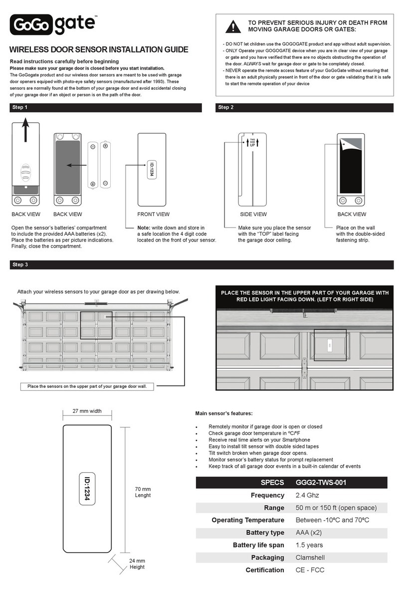
GOGOGATE
GOGOGATE GGG2-TWS-001 installation guide

ADA INSTRUMENTS
ADA INSTRUMENTS Wall Scanner 120 Prof operating manual

Sony
Sony QM-SS1 Help guide
