ELEKTRA ETOG-56T User manual

• ETOG-56T
• ETOR-55
• ETF-744/99
RU
Instrukcja montażu PL
Installation manual UK
Èíñòðóêöèÿ ïî ìîíòàæó
www.elektra.eu
Sensors
for controllers
ETO2-4550 and ETR2-1550


Contents
1. Introductory information 4
2. Types of sensors 4
3. Additional components 5
4. Guidelines for installation 6
4.1 Positioning and installation
of the ETOG-56T sensor 6
4.2 Positioning and installation or ETOR-55
and ETF-744/99 sensors 12
5. Connecting ETOG-56T, ETOR-55
and ETF-744/99 sensors 14
6. Technical data 24
3

1. Introductory information
2. Types of sensors
The Installation manual describes the instal-
lation method for ETOG-56T, ETOR-55 and
ETF-744/99 sensors, and connection to
ETO2-4550 or ETR2-1550 controllers.
To ensure optimal operation of the snow and
ice protection system, installation of the devices
should be conducted according to the guidelines
contained in this manual.
In case of non-standard solutions not covered
by the manual, please contact directly the
Technical Department of the ELEKTRA company.
4
Moisture sensor
ETOR-55
Temperature sensor
ETF-744/99
Temperature
and moisture sensor
ETOG-56T
Sensors for controllers
ETO2-4550 & ETR2-1550

ETOK-T
installation
tube
3. Additional components
ETOK-T installation tube has been included in the
ETOG-56T sensor set. The main task of the tube
is to facilitate installation and eliminate the pos-
sibility of sensor damage during construction
works.
The tube also enables problem-free exchange
of the sensor, if required.
5

4. Guidelines for installation
Selection of the adequate positioning of the
sensor is a key factor to proper operation of
the heating system. It influences directly the
effectiveness of the protection, as well as the
future costs of operation.
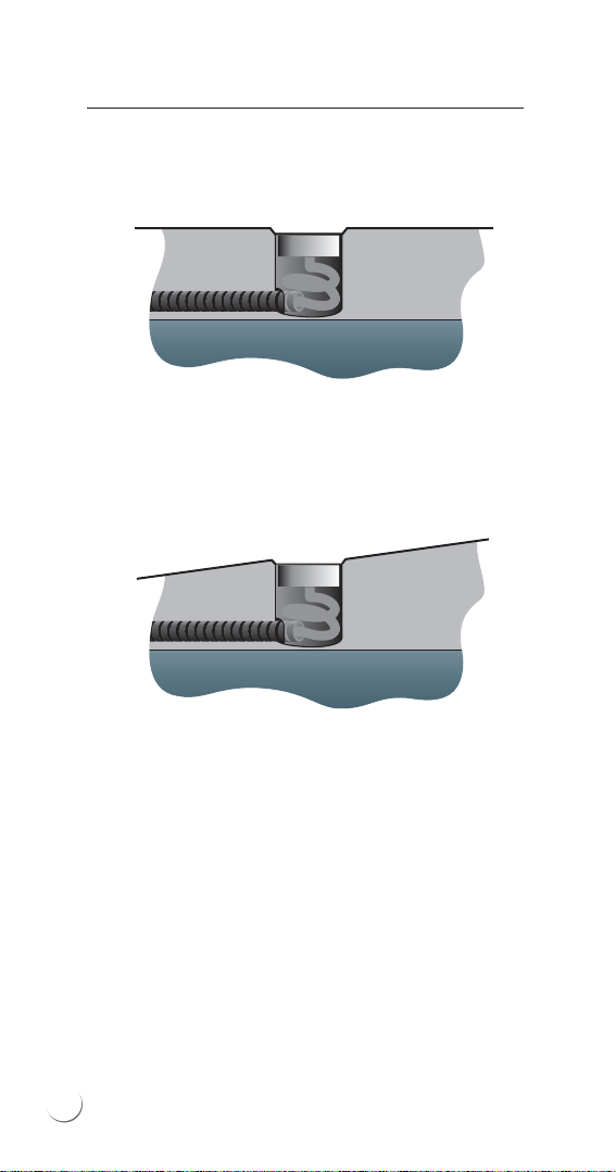
ETOG-56T sensors are to be installed within the
heated area, in an unsheltered position especially
vulnerable to longest expositions to moisture and
low temperatures. This position should also be
exposed to direct rain or snowfall.
In case of heating only the driving tracks, it is
recommended to install the sensor at the edge
of the tracks to be protected. It is possible thus
to avoid snow deposition on the tracks by
vehicles’ wheels. Small amount of snow falling
from the tyres does not constitute any danger
to safe driving, still can cause unnecessary
switching on of the heating system.
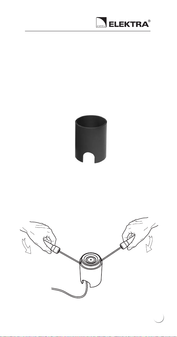
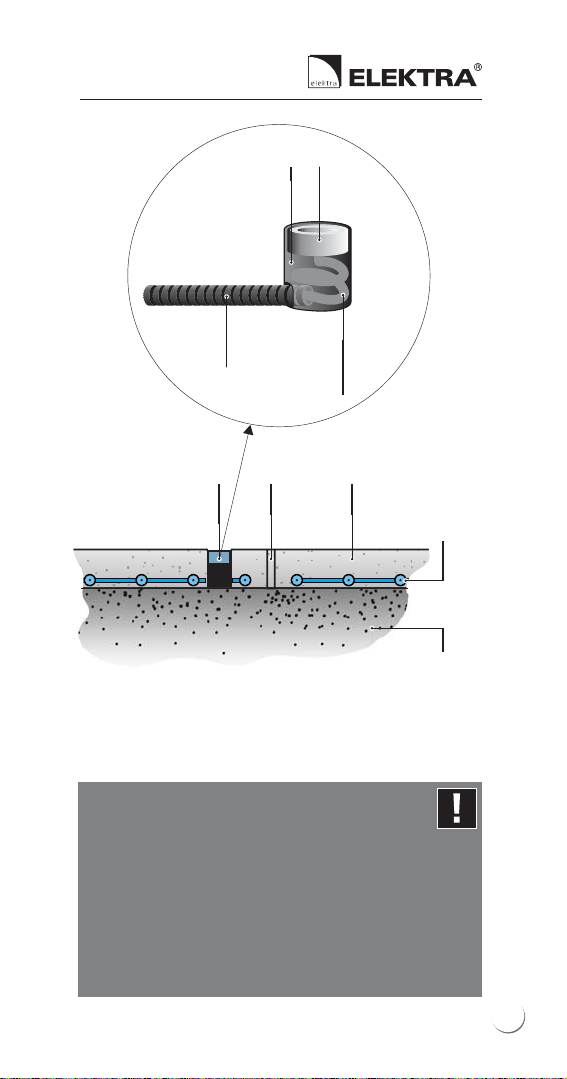
Installation should commence with mounting
of the ETOK-T type protection tube, included
in the set. Lead the protective conduit with the
so called “draw wire” to the planned position
of the sensor, and seal it (after the surface
works have finished, the conduit will help
feeding the sensor’s wire).
4.1 Positioning and installation of the
ETOG-56T sensor
6
Sensors for controllers
ETO2-4550 & ETR2-1550

Then feed the conduit into the ETOK-T tube.
Place the tube between the heating cables, as
the drawing below shows:
Positioning of the installation tube
and ETOG-56T sensor
sensor’s wire in the protective conduit
installation box
min. 10 mm
Mount the ETOK-T installation tube horizontally
so that its upper edge is positioned approx.
5 mm below the surface (this will enable water
deposition on the sensor). Remember to position
the sensor horizontally, regardless of the shape and
inclination of the heated area.
7

After the surface works have finished, feed the
sensor with the wire into the protective conduit
mounted before the surface has been completed.
Pull with the “draw wire” the wire from the
sensor, so as to leave approx. 30 cm excess wire
still remaining inside the tube.
Installation of the sensor in a flat surface
Installation of the sensor in a sloping surface
8
Sensors for controllers
ETO2-4550 & ETR2-1550

sensor’s wire
laid with an
approx. 30 cm
”excess”
protective
conduit
sensorinstallation tube
concrete screed
min. 50 mm thick
compacted
base
expansion
joint
ELEKTRA
heating mat
or cable
temperature and
moisture sensor in the
installation tube
Example of installation of the ETOG-56T sensor
in the concrete surface
Note:
Before pouring concrete, secure the ETOK-T
tube against unnecessary movement and
secure tightly to protect against filling the
inside (adhesive tape, foil, etc.).
It is recommended to check the tube’s
positioning both during pouring concrete,
as well as later, during concrete treatment.
9

Example of installation of the ETOG-56T sensor
in the surface made from paving blocks
compacted
base
paving cobbles
or blocks
ELEKTRA
heating mat
or cable
temperature and
moisture sensor in the
installation tube
sand or sand-cement sub-
crust min. 30 mm thick
sensor’s wire
laid with an
approx. 30 cm
”excess”
protective
conduit
sensorinstallation tube
For asphalt surfaces, during pouring and com-
pacting, replace the ETOK-T installation tube
with a high temperature resistant item such as
a piece of wood, and the protective conduit for
feeding the sensor’s wire should be made of
metal. After asphalt has cured, remove the item
and mount the tube so that its upper edge is
positioned 5 mm below the asphalt surface.
10
Sensors for controllers
ETO2-4550 & ETR2-1550

The area around the tube should be carefully
filled, with no air gap left, the filling material
e.g. cold asphalt could be applied.
asphalt
40-50 mm
thick
compacted
base
ELEKTRA TuffTec™
heating cable or
ELEKTRA SnowTec
heating mat
®Tuff
metal mesh or
ELEKTRA TMS
steel
installation
tape
temperature
and moisture
sensor in the
installation tube
Example of installation of the ETOG-56T sensor
in the asphalt surface
sensor’s wire
laid with an
approx. 30 cm
”excess”
protective
conduit
sensorinstallation tube
11

4.2. Positioning and installation of
ETOR-55 and ETF-744/99 sensors
ETF-744/99 temperature sensor are to be
installed on the northern side of a building,
in the place predicted to be the coolest.
The sensor must not be exposed to direct
sunlight. Additionally, it must be protected
against other factors whose operation might
interfere with the correct temperature measure-
ment, such as: warmth generated by light
beams from floodlights or lamps illuminating
the area, warm air outflow from ventilation
grilles, etc. Installation directly above windows
or doors is not recommended, either.
NS
Installation scheme for the ETF-744/99
temperature sensor and ETOR-55 moisture
sensor
12
Sensors for controllers
ETO2-4550 & ETR2-1550

ETOR-55 sensor should be installed in the vicinity
of gutters or roof channels, possibly close to
downpipes. The optimal position of the sensor
is the southern side of the building.
ETOR-55 sensor should be positioned in the area
protected by heating cables. It is necessary for
the sensor to operate in the horizontal position.
ETOR-55 should be installed so it cannot be
moved, e.g. hooking the control wire to a gutter
grip or an additional flat bar.
13

5. Connecting ETOG-56T,
ETOR-55 and ETF-744/99
sensors
In this chapter examples of connecting sensors
to ETO2-4550 and ETR2-1550 controllers are
shown.
ETOG-56T and ETOR-55 sensors are factory
terminated with a 10 m-long cable. ETF-744/99
sensors are not equipped with a factory cable,
and the connection must be executed
in-house.
The sensors mentioned above can be extended
with a standard installation cable. Max. lengths
and cross-sections are given in the table below.
Sensor
type
Max. cable
length
[m]
Min. cable
cross-section
m[m ]
2
6 x 1.5
4 x 1.5
2 x 1.5
ETOG-56T
ETOR-55
ETF-744/99
200
200
50
14
Sensors for controllers
ETO2-4550 & ETR2-1550

Single-phase electric circuit
Connection diagram of ETR2-1550 controller
with ETOG-56T sensor.
Protection of external surfaces.
single-phase
circuit
sensor’s wire
heating cable
grey
pink
yellow
white
brown
green
N
NL
PE
LL'
PE
L
N
ETOG-56T
+
ETOK-T
15

three-phase
circuit
heating cable
grey
pink
yellow
white
brown
green
Three-phase electric circuit
Connection diagram of ETR2-1550 controller
with ETOG-56T sensor.
Protection of external surfaces.
L2
L1
L3' L2'
N
N
PE
sensor’s wire
ETOG-56T
+
ETOK-T
PE
N
N
L3
L1
L1 L1'
16
Sensors for controllers
ETO2-4550 & ETR2-1550

Single-phase electric circuit
Connection diagram of ETR2-1550 controller
with ETOR-55 and ETF-744/99 sensors.
Protection of roof edges, gutters and downpipes.
heating cable
N
NL
PE
LL'
PE
L
N
yellow
white
brown
green
ETOR-55
ETF-744/99
single-phase
circuit
sensor’s wire
(not included
in the set)
sensor’s
wire
17

ETOR-55
ETF-744/99
sensor’s wire
sensor’s wire
sensor’s wire
(not included in the set)
heating cable
Single-phase electric circuit
Connection diagram of ETO2-4550 controller
with ETOR-55, ETF-744/99 and ETOG-56T sensors.
Protection of roof edges, gutters, downpipes
and external surfaces – two zones.
single-phase
circuit
ETOG-56T
+
ETOK-T
L
PE
N
PE
LL'
L'
L
L
PE
brown
brown
green
green
yellow
white
grey
pink
yellow
white
18
heating cable
Sensors for controllers
ETO2-4550 & ETR2-1550

sensor’s wire
heating cable
Three-phase electric circuit
Connection diagram of ETO2-4550 controller
with ETOG-56T sensor.
Protection of external surfaces - one zone.
three-phase
circuit
ETOG-56T
+
ETOK-T
PE
L3'
PE
L2'
L3
L2
L1
N
N
L1
brown
green
grey
pink
yellow
white
19

sensor’s wire
heating cable
Single-phase electric circuit
Connection diagram of ETO2-4550 controller
with ETOG-56T sensor.
Protection of external surfaces - one zone.
single-phase
circuit
ETOG-56T
+
ETOK-T
PE
PE
L
N
L
N
L'
brown
green
grey
pink
yellow
white
20
Sensors for controllers
ETO2-4550 & ETR2-1550
This manual suits for next models
2
Table of contents
Languages: