Elektro Maschinen PSEm 2505P User manual

36(P3
D
EN
SI
CRO
BEDIENUNGSANLEITUNG
OPERATING INSTRUCTION
NAVODILA ZA UPORABO
UPUTE ZA UPOTREBU
UPUTSTVA ZA UPOTREBU
HASZNÁLATI ÚTMUTATÓT
SRB
MK
HU
Ташев-Галвинг ООД
www.tashev-galving.com

Ташев-Галвинг ООД
www.tashev-galving.com
1
23
7
10
12
13
5
15
2
25 32
4
23
61
52
9
8
11 22
51
50
163
Ташев-Галвинг ООД
www.tashev-galving.com

7
4
6
5
916 35
8
8 9
44
6
35
20
20
max. 5 mm
34
11
34
5
Ташев-Галвинг ООД
www.tashev-galving.com
10 11
14
15
12 13
4
f
14
c
b
a1
g
a14
d
ed
h
Ташев-Галвинг ООД
www.tashev-galving.com

16 17
23
18 19
45°
32 25
26
52
26
22
25
20
10
12 mm
52
25 27 21 26
26
31
25
24
i
25
Ташев-Галвинг ООД
www.tashev-galving.com

22 23
24 25
b
8
36
26
a
27
3
36
14
5
9
Ташев-Галвинг ООД
www.tashev-galving.com
28 29
30 31
b
M6 x 16
a
a
Ташев-Галвинг ООД
www.tashev-galving.com

D
Achtung!
Beim Benutzen von Geräten müssen einige
Sicherheitsvorkehrungen eingehalten werden, um
Verletzungen und Schäden zu verhindern. Lesen Sie
diese Bedienungsanleitung / Sicherheitshinweise
deshalb sorgfältig durch. Bewahren Sie diese gut
auf, damit Ihnen die Informationen jederzeit zur
Verfügung stehen. Falls Sie das Gerät an andere
Personen übergeben sollten, händigen Sie diese
Bedienungsanleitung / Sicherheitshinweise bitte mit
aus. Wir übernehmen keine Haftung für Unfälle oder
Schäden, die durch Nichtbeachten dieser Anleitung
und den Sicherheitshinweisen entstehen.
1. Sicherheitshinweise
Die entsprechenden Sicherheitshinweise finden Sie
im beiliegenden Heftchen!
WARNUNG
Lesen Sie alle Sicherheitshinweise und
Anweisungen. Versäumnisse bei der Einhaltung der
Sicherheitshinweise und Anweisungen können
elektrischen Schlag, Brand und/oder schwere
Verletzungen verursachen zur Folge haben.
Bewahren Sie alle Sicherheitshinweise und
Anweisungen für die Zukunft auf.
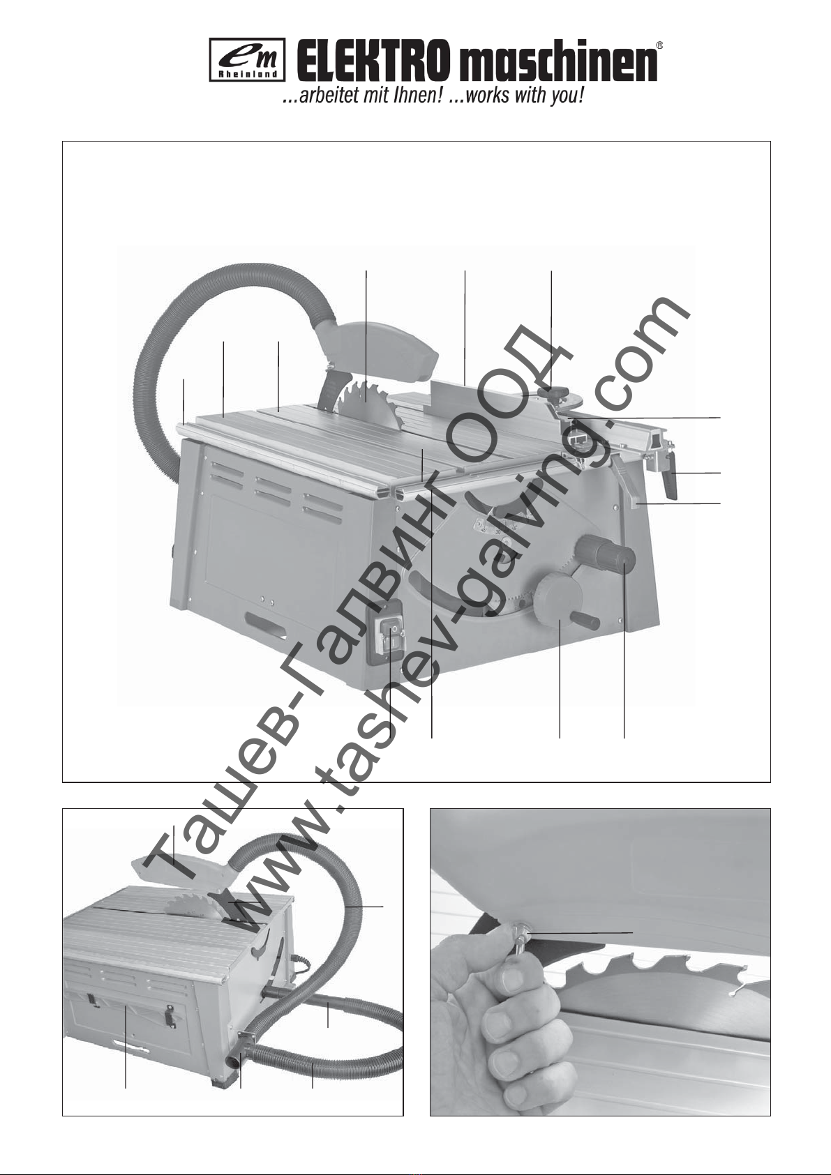
2. Gerätebeschreibung
1 Sägetisch
2 Sägeblattschutz
3 Schiebestock
4 Sägeblatt
5 Spaltkeil
6 Tischeinlage
7 Universalanschlag
8 Handrad/Zugvorrichtung
9 Einstell- und Feststellgriff
10 Klemmhebel
11 Ein-, Ausschalter
12 Exzenterhebel
13 Absaugschlauch
3. Lieferumfang
Unterflur-Zugsäge
Hartmetallbestücktes Sägeblatt
Universalanschlag
Queranschlag
Schiebestock
4. Bestimmungsgemäße Verwendung
Die Säge dient zum Längs- und Querschneiden (nur
mit Queranschlag) von Hölzern aller Art, entsprech-
end der Maschinengröße.
Rundhölzer aller Art dürfen nicht geschnitten
werden.
Die Maschine darf nur nach ihrer Bestimmung
verwendet werden.
Jede weitere darüber hinausgehende Verwendung
ist nicht bestimmungsgemäß. Für daraus hervor-
gehende Schäden oder Verletzungen aller Art haftet
der Benutzer/Bediener und nicht der Hersteller.
Es dürfen nur für die Maschine geeignete Säge-
blätter (HM- oder CV-Sägeblätter) verwendet
werden. Die Verwendung von HSS-Sägeblättern
und Trennscheiben aller Art ist untersagt.
Bestandteil der bestimmungsgemäßen Verwendung
ist auch die Beachtung der Sicherheitshinweise,
sowie der Montageanleitung und Betriebshinweise in
der Bedienungsanleitung.
Personen, die die Maschine bedienen und warten,
müssen mit dieser vertraut und über mögliche
Gefahren unterrichtet sein.
Darüber hinaus sind die geltenden Unfallverhütungs-
vorschriften genauestens einzuhalten.
Sonstige allgemeine Regeln in arbeitsmedizinischen
und sicherheitstechnischen Bereichen sind zu
beachten.
Veränderungen an der Maschine schließen eine
Haftung des Herstellers und daraus entstehende
Schäden gänzlich aus.
Trotz bestimmungsmäßiger Verwendung können
bestimmte Restrisikofaktoren nicht vollständig
ausgeräumt werden. Bedingt durch Konstruktion und
Aufbau der Maschine können folgende Risiken
auftreten:
Berührung des Sägeblattes im nicht abge-
decktem Sägebereich.
Eingreifen in das laufende Sägeblatt
(Schnittverletzung)
Rückschlag von Werkstücken und
Werkstückteilen.
Sägeblattbrüche.
Herausschleudern von fehlerhaften Hartmetall-
teilen des Sägeblattes.
Gehörschäden bei Nichtverwendung des nötigen
Gehörschutzes.
Gesundheitsschädliche Emissionen von Holz-
stäuben bei Verwendung in geschlossenen
Räumen.
Ташев-Галвинг ООД
www.tashev-galving.com

D
Bitte beachten Sie, dass unsere Geräte bestim-
mungsgemäß nicht für den gewerblichen, handwerk-
lichen oder industriellen Einsatz konstruiert wurden.
Wir übernehmen keine Gewährleistung, wenn das
Gerät in Gewerbe-, Handwerks- oder Industriebe-
trieben sowie bei gleichzusetzenden Tätigkeiten ein-
gesetzt wird.
5. Technische Daten
Geräuschemissionswerte
Die angegebenen Werte sind Emissionswerte und
müssen damit nicht zugleich auch sichere Arbeits-
platzwerte darstellen. Obwohl es eine Korrelation
zwischen Emissions- und Immissionspegeln gibt,
kann daraus nicht zuverlässig abgeleitet werden, ob
zusätzliche Vorsichtsmaßnahmen notwendig sind
oder nicht. Faktoren, welche den derzeitigen am
Arbeitsplatz vorhandenen Immissionspegel beein-
flussen können, beinhalten die Dauer der Ein-
wirkungen, die Eigenart des Arbeitsraumes, andere
Geräuschquellen usw., z.B. die Anzahl der
Maschinen und anderen benachbarten Vorgängen.
Die zuverlässigen Arbeitsplatzwerte können ebenso
von Land zu Land variieren. Diese Information soll
jedoch den Anwender befähigen, eine bessere
Abschätzung von Gefährdung und Risiko
vorzunehmen.
6. Vor Inbetriebnahme
Säge auspacken und auf eventuelle Transport-
beschädigungen überprüfen
Die Maschine muß standsicher aufgestellt
werden, d.h. auf einer Werkbank, oder festem
Untergestell festgeschraubt werden.
Vor Inbetriebnahme müssen alle Abdeckungen
und Sicherheitsvorrichtungen ordnungsgemäß
montiert sein.
Das Sägeblatt muß frei laufen können.
Bei bereits bearbeitetem Holz auf Fremdkörper
wie z.B. Nägel oder Schrauben usw. achten.
Bevor Sie den Ein- / Ausschalter betätigen,
vergewissern Sie sich, ob das Sägeblatt richtig
montiert ist und bewegliche Teile leichtgängig
sind.
Überzeugen Sie sich vor dem Anschließen der
Maschine, daß die Daten auf dem Typenschild
mit den Netzdaten übereinstimmen.
Das Untergestell bzw. die Werkbank muss
ausreichend stabil sein und darf während des
Arbeitens nicht kippen.
7. Montage
Achtung! Vor allen Wartungs- Umrüst- und
Montagearbeiten an der Kreissäge ist der
Netzstecker zu ziehen.
7.1 Montage
Die Säge standsicher aufstellen.
Den Absaugadapter (16) mittels der 2 Schrau-
ben (35) an der Hinterseite der Säge, wie in Abb.
5 gezeigt, anschrauben.
Verlängerungsrohr (50) für die untere Staubab-
saugvorrichtung montieren und kürzeren Ab-
saugschlauch (51) an Absaugadapter und Ver-
längerungsrohr anschließen.
7.2 Sägeblattschutz montieren / demontieren
(Abb. 2/3/7)
Sägeblattschutz (2) auf den Spaltkeil (5)
aufsetzen, so daß die Schraube durch das Loch
des Spaltkeils (44) paßt.
Schraube (15) nicht zu fest anziehen; der Säge-
blattschutz muss frei beweglich bleiben.
Absaugschlauch (13) an den Absaugadapter (16)
und am Absaugstutzen des Sägeblatt-schutzes
(2) befestigen.
Am Ausgang des Absaugadapters (16) ist eine
geeignete Absauganlage anzuschließen.
Die Demontage erfolgt in umgekehrter
Reihenfolge.
Achtung!
Vor Sägebeginn muß der Sägeblattschutz (2)
auf das Sägegut abgesenkt werden.
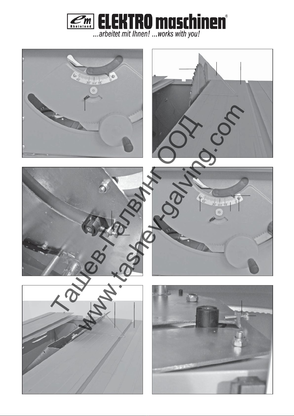
7.3. Spaltkeil einstellen (Abb. 8/9)
Achtung! Netzstecker ziehen
Sägeblatt (4) auf max. Schnittiefe einstellen, in
die 0° Stellung bringen und arretieren.
Sägeblattschutz demontieren (siehe 7.2.)
Tischeinlage (6) herausnehmen (siehe 7.4)
Die 2 Befestigungsschrauben (20) lockern.
Spaltkeil (5) nach oben schieben, bis der
Abstand zwischen Sägetisch (1) und Oberkante
Spaltkeil (5) maximal ist.
Der Abstand zwischen Sägeblatt (4) und
Spaltkeil (5) soll 3-5 mm sein.
Die Schrauben (20) wieder festziehen und Tisch-
einlage (6) montieren.
Um den Abstand zum Sägeblatt (4) zu verringern
bzw. zu vergrößern, müssen die 2
Befestigungsschrauben (20) und der Spaltkeil (5)
demontiert werden. Mit der Inbusschraube (a)
kann die Halterung für den Spaltkeil gelockert
und der Abstand Spaltkeil-Sägeblatt verringert
bzw. vergrößert werden.
Bitte beachten Sie bei der Einstellung des
Spaltkeils den max. Abstand von 5mm, siehe Bild
9. Der min. Abstand darf nicht unter 3mm sein.
Ташев-Галвинг ООД
www.tashev-galving.com

D
7.4 Tischeinlage austauschen (Abb. 6)
Bei Verschleiß oder Beschädigung ist die
Tischeinlage zu tauschen, ansonsten besteht
erhöhte Verletzungsgefahr.
Sägeblattschutz (2) abnehmen
Die 2 Senkkopfschrauben (34) entfernen.
Die verschlissene Tischeinlage (6) heraus-
nehmen.
Die Montage der neuen Tischeinlage erfolgt in
umgekehrter Reihenfolge
7.5 Montage/Wechsel des Sägeblatt (Abb. 7)
Achtung! Netzstecker ziehen.
Die Tischeinlage durch lösen der zwei Senkkopf-
schrauben entfernen (siehe 7.4)
Mutter lösen, indem man einen Schlüssel (SW
24) an der Mutter ansetzt und mit einem weiteren
Gabelschlüssel (SW 13) an der Motorwelle, um
gegenzuhalten, ansetzt. Werkzeug ist im
Lieferumfang nicht enthalten!
Achtung! Mutter in Rotationsrichtung des Säge-
blattes drehen.
Äußeren Flansch abnehmen und altes Säge-
blatt schräg nach unten vom inneren Flansch
abziehen. Sägeblattflansche vor der Montage
des neuen Sägeblattes sorgfältig reinigen
Das neue Sägeblatt in umgekehrter Reihenfolge
wieder einsetzen und festziehen
Achtung! Laufrichtung beachten, die
Schnittschräge der Zähne muß in
Laufrichtung, d.h. nach vorne zeigen (siehe
Pfeil auf dem Sägeblattschutz)
Spaltkeil (5) sowie Sägeblattschutz (2) wieder
montieren und einstellen (siehe 7.2, 7.3)
Bevor Sie mit der Säge wieder arbeiten, ist die
Funktionsfähigkeit der Schutzeinrichtungen zu
prüfen.
7.6 Feinjustierung
7.6.1 Feinjustierung des Anschlags für 0° (90°)
(Abb. 10-13)
Bringen sie den Winkelanschlag (14) in die linke
Stellung
Sägeblatt (4) auf max. Schnitttiefe einstellen, in
0° Stellung bringen.
Tischeinlage heraus nehmen (siehe 7.4).
90° Anschlagwinkel (a) (nicht im Lieferumfang)
zwischen Sägeblatt (4) und Sägetisch (1)
anlegen
Kontermutter (b) lösen und Verstellschraube (c)
soweit verstellen, dass der Winkel zwischen
Sägeblatt (4) und Sägetisch (1) genau 90°
beträgt.
Nun die Kontermutter (b) wieder fixieren.
Durch lösen der Schrauben (d) können sie die
Skala (e) exakt am Pfeil (f) auf 0° ausrichten.
7.6.2 Feinjustierung des Anschlags für 45°
(Abb. 14-15)
45° Anschlagwinkel (a) (nicht im Lieferumfang)
zwischen Sägeblatt (4) und Sägetisch (1)
anlegen
Kontermutter (g) lösen und Verstellschraube (h)
soweit verstellen, dass der Winkel zwischen
Sägeblatt (4) und Sägetisch (1) genau 45°
beträgt.
Nun die Kontermutter (g) wieder fixieren.
Montieren Sie nun die Tischeinlage wieder
Prüfen Sie alle Sicherheitseinrichtungen
7.6.3 Feinjustierung des Parallelanschlag
(Abb. 16)
Durch lösen der Schraube (i) kann die Skala (23)
exakt parallel zum Sägeblatt eingestellt werden.
8. Bedienung
Die Unterflur-Zugsäge kann als Zug-Kreissäge oder
als Tischkreissäge verwendet werden.
Der Betrieb als Unterflur-Zugsäge dient zum
präzisen und sicheren trennen von feststehen-
den Werkstücken, wobei das Sägeaggregat be-
wegt wird.
Der Betrieb als Tischkreissäge dient zum Längs-
schneiden größerer Werkstücke, wobei das
Sägeaggregat fixiert ist und das Werkstück be-
wegt wird.
8.1 Ein/Aus-Schalter (Abb. 4)
Durch Drücken der grünen Taste „I“ kann die
Säge eingeschaltet werden. Vor Beginn des
Sägens abwarten, bis das Sägeblatt seine
maximale Drehzahl erreicht hat.
Um die Säge wieder auszuschalten, muß die rote
Taste „0“ gedrückt werden.
8.2 Schnittiefe (Abb. 4)
Durch Drehen der Handkurbel (8), kann das
Sägeblatt (4) auf die gewünschte Schnittiefe
eingestellt werden.
Entgegen dem Uhrzeigersinn:
größere Schnittiefe
Im Uhrzeigersinn:
kleinere Schnittiefe
Ташев-Галвинг ООД
www.tashev-galving.com

D
8.3.1 Anschlaghöhe
Der mitgelieferte Anschlag (7) besitzt zwei ver-
schieden hohe Führungsflächen.
Je nach Dicke der zu schneidenden Materialien
muß die Anschlagschiene (25) nach Abb. 19, für
dickes Material und nach Abb. 20 für dünnes
Material verwendet werden.
Zum Umstellen der Anschlagschiene (25) auf die
niedere Führungsfläche, müssen die beiden
Flügelschrauben (26) gelockert werden, um die
Anschlagschiene (25) vom Halter (24) zu lösen.
Die beiden Flügelschrauben (26) durch den
einen Schlitz (27) in der Anschlagschiene (25)
herausnehmen und in den anderen Schlitz (31)
wieder einsetzen (Abb. 21).
Anschlagschiene (25) wieder auf den Halter
montieren.
Die Umstellung auf die hohe Führungsfläche
muß analog durchgeführt werden.
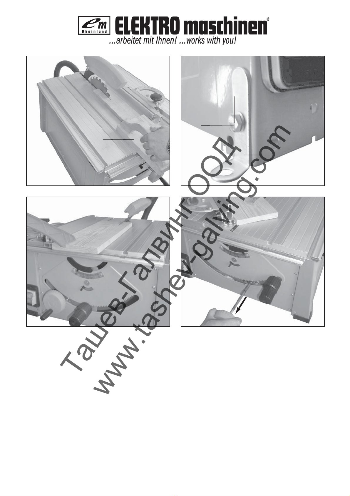
8.3.2 Schnittbreite (Abb. 1)
Beim Längsschneiden von Holzteilen muß ein
Parallelanschlag (7) verwendet werden.
Der Parallelanschlag (7) kann auf beiden Seiten
des Sägetisches (1) montiert werden.
Der Parallelanschlag (7) muß in die vordere
Führungsschiene (22) des Sägetisches (1) ein-
gesetzt werden.
Mittels der Skala (23) auf der Führungsschiene
(22) kann der Parallelanschlag (7) auf das
gewünschte Maß eingestellt werden.
Durch Drücken des Exzenterhebels (12) kann
der Parallelanschlag in der gewünschten Position
festgeklemmt werden.
8.3.3 Anschlaglänge einstellen (Abb. 18)
Um das Klemmen des Schnittgutes zu
vermeiden, ist die Anschlagschiene (25) in
Längsrichtung verschiebbar.
Faustregel: Das hintere Ende des Anschlages
stößt an eine gedachte Linie, die etwa bei der
Sägeblattmitte beginnt und unter 45° nach hinten
verläuft.
Benötigte Schnittbreite einstellen:
Klemmhebel (10) lösen, Anschlag so weit vor-
schieben bis gedachte 45° Linie berührt wird.
Gegebenenfalls auch Anschlagschiene durch
Lösen der Flügelschrauben (26) einstellen.
Klemmhebel und Flügelschrauben nach dem
Einstellen wieder festziehen.
8.4. Queranschlag (Abb. 17)
Universalanschlag in der linken oder rechten
Führungsschiene (52) mit Hilfe des Exzenter-
hebels (12) in der gewünschten Position fest-
klemmen
Anschlag durch lösen des Klemmhebels (10) auf
gewünschte seitliche Position einstellen und
Hebel wieder festklemmen.
Durch lösen der Rändelschraube (32) gewün-
schten Winkel am Queranschlag einstellen und
Rändelschraube wieder festziehen. Die Winkel-
einstellung verfügt über eine Rasterung für alle
gängigen Winkelmaße.
Durch lösen der beiden Flügelschrauben (26) die
Anschlagschiene einstellen.
Achtung!
Anschlagschiene (25) nicht zu weit in Richtung
Sägeblatt schieben.
Der Abstand zwischen Anschlagschiene (25) und
Sägeblatt (4) sollte ca. 12 mm betragen.
8.3 Parallelanschlag
8.5. Winkeleinstellung (Abb. 24)
Feststellgriff (9) lösen
Durch Drehen des Griffes das gewünschte
Winkelmaß an der Skala einstellen.
Feststellgriff in gewünschter Winkelstellung
arretieren.
Die Säge verfügt über einen Winkelanschlag
(14).
Ist Winkelanschlag in linker Position (Abb. 24),
ist der Anschlag auf 0° bzw. 45° aktiv.
Ist Winkelanschlag in rechter Position, kann ein
Sägeblattwinkel bis max. –2° bzw. + 47° einge-
stellt werden.
8.6 Einsatz als Unterflur-Zugsäge
Zum Einsatz als Unterflur-Zugsäge muss die Sperre
(36) des Sägeaggregates entsperrt werden.
Dazu Zugvorrichtung (8) leicht nach außen ziehen
und Sperre lösen. (Abb. 23)
8.7 Einsatz als Tischkreissäge (Abb. 22/23)
Für den Einsatz als Tischkreissäge muss das
Sägeaggregat fest fixiert werden.
Dazu Sperre in einer der beiden Nuten (a/b) der
Zugstange einrasten lassen. (Abb.22/23). Nach
dem Einrasten prüfen, ob Sperre (36) wirksam
ist.
Bei einer Fixierung in der mittleren Nut (b) hat
man beim Betrieb eine größere Werkstückauf-
lage auf der Hinterseite des Sägetisches zur
Verfügung.
Ташев-Галвинг ООД
www.tashev-galving.com

D
9. Betrieb
Achtung!!
Nach jeder neuen Einstellung empfehlen wir
einen Probeschnitt, um die eingestellten Maße
zu überprüfen.
Nach den Einschalten der Säge abwarten, bis
das Sägeblatt seine maximale Drehzahl erreicht
hat, bevor Sie den Schnitt durchführen.
Achtung beim Einschneiden!
Die Säge ist vor dem Gebrauch mit den
mitgelieferten Metallwinkeln (a) festzuschrauben!
Dazu müssen, wie in Abb. 29 gezeigt die
Metallwinkel (a) mit den Schrauben (b) am
Maschinenkörper befestigt werden.
9.1 Ausführen von Längsschnitten (Abb. 26)
Hierbei wird ein Werkstück in seiner Längsrichtung
durchschnitten. Achtung! Das Sägeaggregat muß
fixiert sein (siehe 8.7).
Eine Kante des Werkstücks wird gegen den
Parallelanschlag (7) gedrückt, während die flache
Seite auf dem Sägetisch (1) aufliegt.
Der Sägeblattschutz (2) muß immer auf das
Werkstück abgesenkt werden.
Die Arbeitsstellung beim Längsschnitt darf nie in
einer Linie mit dem Schnittverlauf sein.
Parallelanschlag (7) entsprechend der
Werkstückhöhe und der gewünschten Breite
einstellen. (siehe 8.3.)
Säge einschalten
Hände mit geschlossenen Fingern flach auf das
Werkstück legen und Werkstück am
Parallelanschlag (7) entlang in das Sägeblatt (4)
schieben.
Seitliche Führung mit der linken oder rechten
Hand (je nach Position des Parallelanschlages)
nur bis zur Schutzhaubenvorderkante.
Werkstück immer bis zum Ende des Spaltkeils
(5) durchschieben.
Der Schnittabfall bleibt auf dem Sägetisch (1)
liegen, bis sich das Sägeblatt (4) wieder in
Ruhestellung befindet.
Werkstücke gegen Abkippen am Ende des
Schneidevorgangs sichern! (z.B. Abrollständer
etc.)
9.1.2. Schneiden schmaler Werkstücke (Abb. 27)
Längsschnitte von Werkstücken mit einer Breite
von weniger als 120 mm müssen unbedingt
unter Zuhilfenahme eines Schiebestockes (3)
durchgeführt werden. Schiebestock ist im
Lieferumfang enthalten.
Verschlissenen bzw. beschädigten
Schiebestock umgehend austauschen.
9.1.3. Schneiden sehr schmaler Werkstücke
(Abb. 28)
Für Längsschnitte von sehr schmalen
Werkstücken mit einer Breite von 30 mm und
weniger ist unbedingt ein Schiebeholz (a) zu ver-
wenden.
Dabei ist die niedrige Führungsfläche des
Parallelanschlages zu bevorzugen.
Schiebeholz nicht im Lieferumfang
enthalten!(Erhältlich im einschlägigen
Fachhandel)
Verschlissenes Schiebeholz rechtzeitig
ersetzen.
9.1.4. Ausführen von Schrägschnitten
(Abb. 24/30)
Schrägschnitte werden grundsätzlich unter der
Verwendung des Parallelschlages (7) durchgeführt.
Sägeblatt (4) auf das gewünschte Winkelmaß
einstellen. (siehe 8.5.)
Parallelanschlag (7) je nach Werkstückbreite und
-höhe einstellen (siehe 8.3.1)
Schnitt entsprechend der Werkstückbreite
durchführen (siehe 9.1.1. und 9.1.2 und 9.1.3.)
9.1.5. Ausführung von Querschnitten (Abb. 25/31)
Querschnitte werden mit Hilfe der Zugfunktion
getätigt.
Gewünschten Sägeblatt-Winkel einstellen
(siehe 8.5)
Universalanschlag wie in Kap 8.4 verwenden
Werkstück mit einer Hand gut festhalten und
gegen die Anschlagschiene drücken
Mit der anderen Hand das Sägeblatt an der
Zugvorrichtung (8) langsam nach vorne durch
das Werkstück ziehen.
Nach dem Schnitt das Sägeaggregat nicht zu-
rückschnellen lassen, sondern langsam von
Hand zurückführen.
Säge wieder ausschalten. Sägeabfall erst
entfernen, wenn das Sägeblatt stillsteht.
10. Austausch der
Netzanschlussleitung
Wenn die Netzanschlussleitung dieses Gerätes
beschädigt wird, muss sie durch den Hersteller oder
seinen Kundendienst oder eine ähnlich qualifizierte
Person ersetzt werden, um Gefährdungen zu
vermeiden.
Ташев-Галвинг ООД
www.tashev-galving.com

D
11. Reinigung, Wartung und
Ersatzteilbestellung
Ziehen Sie vor allen Reinigungsarbeiten den
Netzstecker.
11.1 Reinigung
Halten Sie Schutzvorrichtungen, Luftschlitze und
Motorengehäuse so staub- und schmutzfrei wie
möglich. Reiben Sie das Gerät mit einem
sauberen Tuch ab oder blasen Sie es mit
Druckluft bei niedrigem Druck aus.
Wir empfehlen, dass Sie das Gerät direkt nach
jeder Benutzung reinigen.
Reinigen Sie das Gerät regelmäßig mit einem
feuchten Tuch und etwas Schmierseife.
Verwenden Sie keine Reinigungs- oder
Lösungsmittel; diese könnten die Kunststoffteile
des Gerätes angreifen. Achten Sie darauf, dass
kein Wasser in das Geräteinnere gelangen kann.
11.2 Wartung
Achtung! Netzstecker ziehen.
Staub und Verschmutzungen sind regelmäßig
von der Maschine zu entfernen. Die Reinigung
ist am besten mit einer feinen Bürste oder einem
Lappen durchzuführen.
11.3 Ersatzteilbestellung:
Bei der Ersatzteilbestellung sollten folgende
Angaben gemacht werden;
Typ des Gerätes
Artikelnummer des Gerätes
Ident-Nummer des Gerätes
Ersatzteilnummer des erforderlichen Ersatzteils
12. Entsorgung und Wiederverwertung
Das Gerät befindet sich in einer Verpackung um
Transportschäden zu verhindern. Diese Verpackung
ist Rohstoff und ist somit wieder verwendbar oder
kann dem Rohstoffkreislauf zurückgeführt werden.
Das Gerät und dessen Zubehör bestehen aus
verschiedenen Materialien, wie z.B. Metall und
Kunststoffe. Führen Sie defekte Bauteile der
Sondermüllentsorgung zu. Fragen Sie im
Fachgeschäft oder in der Gemeindeverwaltung nach!
Benutzen Sie zur Reinigung des Kunststoffes
keine ätzenden Mittel.
Zugfunktion des Sägeaggregates sauber halten
und in regelmäßigen Abständen nachschmieren.
Ташев-Галвинг ООД
www.tashev-galving.com

7HFKQLVFKH'DWHQ
36(P39
!"
! #$
%!!&' ( )
*'
+!&$
,-
,-,-.)/
! !01,2& .
% !2&345
6!2&35
!!7!
, !2&
)2&
"""
"""
*22 !
62 !
7!32 !5
7!38&&5
90 !,& " :
9 !&&(*& !%#
;<35=
*&+
6
!&&(% ,&!%#;#>).
3??51#>?.@??3;5=
*&+
6
1635
1635
1635
1635
)
?.
?.
A ! B ("""C)
&2,&('1D !
:&&2@
:&&2@
=%-1;0181 !& ! ! !&0
1&&">0!&:&0 !;<1#&,1 !E&2
&012& ! !4!0111 !"F,0& !1,&&
&2 !& !E!1#&!&1;111
92 !D&&1"!"1G!&1' !11 !E2"%&2
&0,7E*1*1E"%#+&&H1 !101+2!
!2E9+2!11I,E!"
D
Professional Line
Ташев-Галвинг ООД
www.tashev-galving.com

Important!
When using equipment, a few safety precautions
must be observed to avoid injuries and damage.
Please read the complete operating manual with due
care. Keep this manual in a safe place, so that the
information is available at all times. If you give the
equipment to any other person, give them these
operating instructions as well.
We accept no liability for damage or accidents which
arise due to non-observance of these instructions
and the safety information.
1. Safety regulations
The corresponding safety information can be found
in the enclosed booklet.
CAUTION!
Read all safety regulations and instructions.
Any errors made in following the safety regulations
and instructions may result in an electric shock, fire
and/or serious injury.
Keep all safety regulations and instructions in a
safe place for future use.
2. Layout
1 Saw table
2 Saw blade guard
3 Push stick
4 Saw blade
5 Splitter
6 Table insert
7 Universal stop
8 Handwheel/drag device
9 Adjusting and locking grip
10 Clamping lever
11 ON/OFF switch
12 Eccentric lever
13 Extractor hos
3. Items supplied
Underswing drag saw
Carbide-tipped saw blade
Universal stop
Cross stop
Push stick
4. Proper use
The bench-type circular saw is designed for the
slitting and cross-cutting (only with the cross stop) of
all types of timber, commensurate with the machineʼs
size.
The machine is not to be used for cutting any type of
roundwood.
The machine is to be used only for its prescribed
purpose.
Any other use is deemed to be a case of misuse.
The user/operator and not the manufacturer will be
held liable for damage and/or injuries of any kind that
result from such misuse. The machine is to be
operated only with suitable saw blades (saw blades
made of HM or CV) It is prohibited to use any type of
HSS saw blade and cutting-off wheel. To use the
machine properly you must also observe the safety
regulations, the assembly instructions and the
operating instructions to be found in this manual.
All persons who use and service the machine have
to be acquainted with this manual and must be
informed about the machineʼs potential hazards.
It is also imperative to observe the accident
prevention regulations in force in your area.
The same applies for the general rules of
occupational health and safety.
The manufacturer shall not be liable for any changes
made to the machine nor for any damage resulting
from such changes.
Even when the machine is used as prescribed it is
still impossible to eliminate certain residual risk
factors. The following hazards may arise in
connection with the machineʼs construction and
design:
Contact with the saw blade in the uncovered saw
zone.
Reaching into the running saw blade (cut
injuries).
Kick-back of workpieces and parts of work-
pieces.
Saw blade fracturing.
Catapulting of faulty carbide tips from the saw
blade.
Damage to hearing if ear-muffs are not used as
necessary.
Harmful emissions of wood dust when used in
closed rooms.
Please note that our equipment has not been
designed for use in commercial, trade or industrial
applications. Our warranty will be voided if the
machine is used in commercial, trade or industrial
businesses or for equivalent purposes.
EN
Ташев-Галвинг ООД
www.tashev-galving.com

EN
5. Technical data
Noise emission values
„The quoted values are emission values and not
necessarily reliable workplace values. Although there
is a correlation between emission and immission
levels it is impossible to draw any certain conclusions
as to the need for additional precautions. Factors
with a potential influence on the actual immision level
at the workplace include the duration of impact, the
type of room, and other sources of noise etc., e.g.
the number of machines and other neighbouring
operations. Reliable workplace values may also vary
from country to country. With this information the
user should at least be able to make a better
assessment of the dangers and risks involved.“
6. Before starting the equipment
Unpack the saw and check it for damage which
may have occurred in transit.
The machine has to be set up where it can stand
firmly, e.g. on a work bench, or it must be bolted
to a strong base.
All covers and safety devices have to be properly
fitted before the machine is switched on.
It must be possible for the saw blade to run
freely.
When working with wood that has been
processed before, watch out for foreign bodies
such as nails or screws, etc.
Before you actuate the On/Off switch, make sure
that the saw blade is correctly fitted and that the
machineʼs moving parts run smoothly.
Before you connect the machine to the power
supply, make sure the data on the rating plate is
the same as that for your mains.
It is imperative that the base frame or workbench
is sufficiently stable and does not topple while
you are working.
7. Assembly
Important! Pull out the power plug before
carrying out any maintenance, resetting or
assembly work on the cutting-off machine!
7.1 Assembly
Place the saw on a flat and firm surface.
Fasten the extractor adapter (16) with the 2
screws (35) to the back of the saw as shown in
Fig. 5.
Fit the extension pipe (50) for the lower dust
extraction device and the short extractor hose
(51) to the extractor adapter and extension pipe.
7.2 Fitting / removing the saw blade guard
(Fig. 2/3/7)
Mount the saw blade guard (2) on the splitter (5)
so that the screw fits through the hole (44) in the
splitter.
Do not tighten the screw (15) too far – the blade
guard must be able to move freely.
Fasten the extractor hose (13) to the extractor
adapter (16) and to the extractor socket of the
blade guard (2).
A suitable extractor system has to be connected
to the outlet of the extractor adapter (16).
To remove the saw blade guard, proceed in
reverse order.
Important!
The guard hood (2) must always be lowered over
the workpiece before you begin to cut.
7.3. Setting the splitter (Fig. 8/9)
Important! Pull out the power plug.
Set the blade (4) to max. cutting depth, move to
0° position and lock in place.
Remove the saw blade guard (see 7.3).
Take out the table insert (6) (see 7.4).
Slacken the fixing screw (20).
Push up the splitter (5) until the gap between the
saw table (1) and the upper edge of the splitter
(5) equals approx. 10 cm.
The distance between the blade (4) and the
splitter (5) should be 3-5 mm.
Retighten the screw (20) and mount the table
insert (6) (Fig. 7).
To decrease or increase the distance to the saw
blade (4), the 2 fastening screws (20) and the
splitter must be removed (5). Using the Allen
screw (a) you can slacken the holder for the
splitter and decrease or increase the distance
between the splitter and the saw blade.
When adjusting the splitter please note that the
maximum distance is 5mm (see Figure 9). The
minimum distance must not be less than 3mm.
7.4 Changing the table insert (Figure 6)
To prevent increased likelihood of injury the table
insert should be changed whenever it is worn or
damaged.
Remove the saw blade guard (2).
Remove the 2 countersunk head screws (34).
Take out the worn table insert (6).
To fit the replacement table insert, proceed in
reverse order.
7.5 Fitting/replacing the blade (Fig. 7)
Important! Pull out the power plug first.
Remove the table insert by undoing the two
countersunk head screws (see 7.4).
Ташев-Галвинг ООД
www.tashev-galving.com

EN
Undo the nut with a size 24 wrench on the nut
itself and a second fork wrench (size 13) on the
motor shaft to apply counter-pressure.
Important! Turn the nut in the direction of
rotation of the saw blade.
Take off the outer flange and pull the old saw
blade off the inner flange by dropping the blade
at an angle.
Clean the blade flange thoroughly before fitting
the new blade.
Mount and fasten the new saw blade in reverse
order.
Important! Note the running direction. The
cutting angle of the teeth must point in
running direction, i.e. forwards (see the arrow
on the blade guard).
Refit and set the splitter (5) and the saw guard
(2) (see 7.3., 7.4.)
Check to make sure that all safety devices are
properly mounted and in good working condition
before you begin working with the saw again.
7.6 Final adjustment
7.6.1 Final adjustment of the stop for 0° (90°)
(Fig. 10-13)
Move the angle stop (14) to its left-hand position
Set the blade (4) to max. cutting depth and move
it to the 0° position.
Remove the table insert (see 7.4).
Place the 90° stop angle (a) (not supplied)
between the saw blade (4) and saw table (1)
Slacken the counternut (b) and adjust the
adjustment screw (c) so that the angle between
the saw blade (4) and the saw table (1) is exactly
90°.
Now tighten the counternut (b) again.
By undoing the screws (d) you can align the
scale (e) precisely to the arrow (f) on 0°.
7.6.2 Final adjustment of the stop for 45°
(Fig. 14-15)
Place the 45° stop angle (a) (not supplied)
between the saw blade (4) and saw table (1)
Slacken the counternut (g) and adjust the
adjustment screw (h) so that the angle between
the saw blade (4) and the saw table (1) is exactly
45°.
Now tighten the counternut (g) again.
Fit the table insert again
Check all the safety equipment
7.6.3 Final adjustment of the parallel stop
(Fig. 16)
By undoing the screw (i) it is possible to adjust the
scale (23) precisely parallel with the saw blade.
8. Operation
The underswing drag saw can be used as a drag
circular saw or as a bench-type circular saw.
It is used as a drag circular saw to make precise
and safe cuts in stationary workpieces, i.e. the
saw unit is moved.
It is used as a bench-type circular saw to make
longitudinal cuts in larger workpieces, i.e. the
saw unit is fixed and the workpiece is moved.
8.1. ON/OFF switch (Fig. 4)
To turn the saw on, press the green button .”I.” .
Wait for the blade to reach its maximum speed of
rotation before commencing with the cut.
To turn the machine off again, press the red
button “0”.
8.2. Cutting depth (Fig. 4)
Turn the hand crank (8) to set the blade (4) to
the required cutting depth.
Turn anti-clockwise:
larger cutting depth
Turn clockwise:
smaller cutting depth
8.3. Parallel stop
8.3.1. Stop height
The parallel stop (7) supplied with the bench-
type circular saw has two different guide faces.
For thick material you must use the stop rail (25)
as shown in Fig. 19, for thin material you must
use the stop rail as shown in Fig. 20.
To change over the stop rail (25) to the lower
guide face you have to slacken the two knurled
screws (26) in order to disconnect the stop rail
(25) from the holder (24).
Remove the two knurled screws (26) through the
one slot (27) in the stop rail (25) and insert in the
other slot (31). (Fig. 21)
Remount the stop rail (25) on the holder (24).
The procedure for changing over to the high
guide face is similar.
8.3.2. Cutting width (Fig. 1):
The parallel stop (7) has to be used when
making longitudinal cuts in wooden workpieces.
The parallel stop (7) can be mounted on either
side of the saw table (1).
The parallel stop (7) has to be mounted in the
guide rail (22) of the saw table (1).
The parallel stop (7) can be set to the required
dimension with the help of the scale (23) on the
guide rail (22).
Ташев-Галвинг ООД
www.tashev-galving.com

EN
8.3.3. Setting the stop length (Fig. 18)
The stop rail (25) can be moved in longitudinal
direction in order to prevent the workpiece from
becoming jammed.
Rule of thumb: The rear end of the stop comes
up against an imaginary line that begins roughly
at the center of the blade and runs at an angle of
45° to the rear.
Set the required cutting width
- Slacken the knurled screws (26) and push the
stop rail (25) forward until it touches the
imaginary 45° line. Retighten the knurled screws
(26).
8.4. Cross stop (Figure 17)
Use the eccentric lever (12) to clamp the
universal stop in the required position in the left
or right guide rail (52).
Release the clamping lever (10) to set the stop to
the required lateral position and then secure the
lever again.
Undo the knurled screw (32) to set the required
angle on the cross stop and then tighten the
knurled screw again. The angle setting device
has notched positions for all standard angle
sizes.
The stop rail can be adjusted by undoing the two
thumb screws (26).
Important!
Do not push the stop rail (25) too far toward the
blade.
The distance between the stop rail (25) and the
blade (4) should be approx. 12 mm.
8.5. Setting the angle (Fig. 24)
Undo the fixing handle (9).
Turn the handle to set the desired angle on the
scale.
Lock the fixing handle again in the required angle
position.
The saw comes with an angle stop (14).
When the angle stop is in the left position (Fig.
24), the stop is active at 0° or 45°.
When the angle stop is in the right position you
can set a saw blade angle up to max. -2° or
+47°.
8.6 Use as an underswing drag saw
For use as an underswing draw saw the lock (36) of
the saw unit has to be released.
This is done by pulling the drag device (8) slightly
outwards and releasing the lock (Fig. 23).
8.7 Use as a bench-type circular saw (Fig. 22/23)
For use as a bench-type circular saw the saw unit
has to be fixed in place.
This is done by engaging the lock in one of the
two grooves (a/b) of the draw bar (Fig. 22/23).
After the lock (36) latches in place, check that it
is effective.
If the saw unit is fixed in the middle groove (b)
you will have a larger workpiece support on the
rear side of the table.
You can clamp the parallel stop in the required
position by pressing the eccentric lever (12).
9. Operation
Important!!
After every new adjustment we recommend you
to make a trial cut in order to check the new
settings.
After switching on the saw, wait for the blade to
reach its maximum speed of rotation before
commencing with the cut.
Take extra care when starting the cut!
Before use, the saw must be screwed securely to
the metal angle brackets (a) supplied! To do this,
the metal bracket (a) must be secured to the
machine body with the screws (b) as shown in
Fig. 29.
9.1. Making longitudinal cuts (Figure 26)
Longitudinal cutting (also known as slitting) is when
you use the saw to cut along the grain of the wood.
Important! The saw unit must be fixed in place (see
8.7).
Press one edge of the workpiece against the parallel
stop (7) while the flat side lies on the saw table (1).
The guard hood (2) must always be lowered over the
workpiece.
When you make a longitudinal cut, never adopt a
working position that is in line with the cutting
direction.
Set the parallel stop (7) in accordance with the
workpiece height and the desired width. (See
8.3.)
Switch on the saw.
Place your hands (with fingers closed) flat on the
workpiece and push the workpiece along the
parallel stop (7) and into the blade (4).
Guide at the side with your left or right hand
(depending on the position of the parallel stop)
only as far as the front edge of the guard hood.
Always push the workpiece through to the end of
the splitter (5).
The offcut piece remains on the saw table (1)
until the blade (4) is back in its position of rest.
Secure long workpieces against falling off at the
end of the cut (e.g. with a roller stand etc.) .
Ташев-Галвинг ООД
www.tashev-galving.com

9.1.2. Cutting narrow workpieces (Fig. 27)
Be sure to use a push stick (3) when making
longitudinal cuts in workpieces smaller than 120
mm in width. A push block is supplied with the
saw!
Replace a worn or damaged push stick
immediately.
9.1.3. Cutting extremely narrow workpieces
(Fig. 28)
Be sure to use a push block (a) when making
longitudinal cuts in very narrow workpieces with
a width of 30 mm and less.
The low guide face of the parallel stop is best
used in this case.
There is no push block supplied with the
saw! (Available from your specialist
dealer)Replace the push block without delay
when it becomes worn.
9.1.4. Making bevel cuts (Fig. 24/30)
Bevel cuts must always be used using the parallel
stop (7).
Set the blade (4) to the desired angle. (See 8.5.)
Set the parallel stop (7) in accordance with the
workpiece width and height (see 8.3.1)
Carry out the cut in accordance with the
workpiece width (see 9.1.1., 9.1.2 and 9.1.3.)
9.1.5. Making cross cuts (Fig. 25/31)
Cross cuts are made with the help of the drag
function.
Set the saw blade to the desired angle (see 8.5).
Use the universal stop as explained in Section
8.4.
Hold the workpiece firmly with one hand and
press it against the stop rail.
With the other hand slowly pull the saw blade on
the drag device (8) forwards through the
workpiece.
When you have finished the cut, do not allow the
saw unit to jump back into starting position on its
own but guide it back slowly by hand.
Switch off the saw again.
Do not remove the offcut until the blade has
stopped rotating.
10.Replacing the power cable
If the power cable for this equipment is damaged, it
must be replaced by the manufacturer or its after-
sales service or similarly trained personnel to avoid
danger.
11. Cleaning, maintenance and
ordering of spare parts
Always pull out the mains power plug before starting
any cleaning work.
11.1 Cleaning
Keep all safety devices, air vents and the motor
housing free of dirt and dust as far as possible.
Wipe the equipment with a clean cloth or blow it
with compressed air at low pressure.
We recommend that you clean the device
immediately each time you have finished using it.
Clean the equipment regularly with a moist cloth
and some soft soap. Do not use cleaning agents
or solvents; these could attack the plastic parts
of the equipment. Ensure that no water can seep
into the device.
11.2 Maintenance
Important! Pull out the power plug first.
Remove dust and dirt regularly from the
machine. Cleaning is best carried out with a fine
brush or a cloth.
Never use caustic agents to clean plastic parts.
Keep the saw unit drag device clean and
lubricate it in regular intervals.
11.3 Ordering replacement parts:
Please quote the following data when ordering
replacement parts:
Type of machine
Article number of the machine
Identification number of the machine
Replacement part number of the part required
12. Disposal and recycling
The unit is supplied in packaging to prevent its being
damaged in transit. This packaging is raw material
and can therefore be reused or can be returned to
the raw material system.
The unit and its accessories are made of various
types of material, such as metal and plastic.
Defective components must be disposed of as
special waste. Ask your dealer or your local council.
EENN
Ташев-Галвинг ООД
www.tashev-galving.com
Table of contents
Languages:
Other Elektro Maschinen Saw manuals

Popular Saw manuals by other brands


Parkside
Parkside MPKZ 2000 A1 Operating and safety instructions

Erbauer
Erbauer ERI490CSW Original instructions

BN Products
BN Products BNCE-20-24 V SN Operation & instruction manual

PSI Woodworking Products
PSI Woodworking Products MLCUTOFF User manua

Ryobi
Ryobi RTS10 Repair sheet

EINHELL Bavaria
EINHELL Bavaria BMP 440E operating instructions

DeWalt
DeWalt D28715 Original instructions

Makita
Makita LS1214FL instruction manual

EINHELL
EINHELL TE-TS 36/210 Li-Solo Original operating instructions

Hitachi
Hitachi C12LCH Safety instructions and instruction manual

Power Craft
Power Craft 48205 instruction manual

Grizzly
Grizzly g0555lanv insert Manual insert