Element 878D User manual
MadeinChina
Statement:Thecompanyreservestherighttoimprove&upgradeproducts,
product specifications and design are subject to change without notice.
Thank you for purchasing this product. Please read the manual
carefullybeforeoperatingandkeepthismanualforfuturereference.
English
O P E R AT I O N
INSTRUCTION
2-IN-1 Rework Station
ESD Safe
04.07.03.279878d/878ad

I. APPLICATIONS
1. This unit is suitable for desoldering & soldering operations on a broad range of components. E.g., SOIC, CH-
IP, QFP, PLCC, BGA, SMD, and more. The unit is especially suited for desoldering operations on in-line sock-
ets.
2. You can use this unit for heat shrinking, drying, paint removal, glue removal, defrosting, pre-heating, glue
soldering, and more.
II. CONTROL PANEL
1. Temperature Increase Button (Hot Air Rework Station)
2. Temperature Decrease Button (Hot Air Rework Station)
3. Air Volume Adjustment Knob
4. Cord (Hot Air Gun)
5. Power Switch (Hot Air Rework Station)
6. Receptacle (Soldering Iron)
7. Power Switch (Soldering Station)
8. Temperature Adjustment Knob (Soldering Station)
9. Operation Indicator (Soldering Station)
10. Temperature Display (Hot Air Rework Station)
III. OPERATION
Hot Air Rework Station
1. Set the station appropriately. Install the hot air gun holder onto the left side of the station, and
place the hot air gun in its holder.
2. Install the required nozzle(Use of nozzles in larger diameters is recommended). Connect the st-
ation’s power cord to an electrical outlet.
3. Turn ON the master power switch located at the rear of the station, then turn ON the hot air rewo-
rk station’s power switch. The hot air temperature display will show “---” to indicate the gun in st-
andby mode. Press the temperature increase or decrease button to set the desired temperature.
Pick up the hot air gun, and it will enter standard operation mode, the hot air rework station’s op-
eration indicator light (the dot located at the bottom-right of the hot air temperature display) will
turn ON.
The indicator light will stay ON when the hot air gun is heating up, blink rapidly when the temper-
ature is stabilized, turn OFF when the hot air gun is cooling off. Adjust the air volume adjustment
knob to set the appropriate air volume, and begin operation once the temperature is stabilized.
Once the temperature is stabilized, its status is clearly indicated with a rapidly flashing operation
indicator. The precision PID program is tracking and compensating the hot air gun’s temperature
every millisecond, the hot air gun’s temperature is now in a stable, and precise thermostatic state.
4. The hot air gun must be placed back in the holder when the operation is complete, and turn OFF
the hot air rework station’s power switch. The hot air gun’s operation indicator will turn OFF and
the hot air gun then enters cooling mode. When the hot air gun cools to below 100°C/212°F, the
hot air rework station’s temperature display will turn OFF. If the station is not in use for an exten-
ded period, turn OFF the station’s power switch and DISCONNECT the station’s power cord.
5. Digital Temperature Calibration (Hot Air Rework Station)
Temperature discrepancies may occur due to the change in the environment’s temperature, or the rep-
lacement of the heating element and other components. You can correct the discrepancies with this fu-
nction. The temperature calibration function can improve work efficiency and prolong the lifespan of
the heating element.
2
3
4
7
8
9
10
1
5
6
SPECIFICATIONS
0℃~40℃/32℉~104℉
L148*W99*H140mm±5mm
Brushlessblowerwithsmoothairdelivery
≤120L/min
100〜480℃/212℉〜896℉
200〜480℃/392℉〜896℉
LED
<2ohms
LEDNixieTube
Mainunitdimensions
Operatingambienttemperature
HotAirReworkStation
AirDelivery
AirVolume
Temperaturerange
Display
SolderingStation
Temperaturerange
Display
Solderingtiptogroundresistance
Indicator for real-time temperature
tracking & compensation
04
IV. MAINTENANCE & PRECAUTIONS
Hot Air Rework Station
4. Keep a minimum distance of 2mm between the object and the hot air gun’s air outlet.
5. DO NOT allow the hot air to come in direct contact with facial parts, and beware of the danger
of burn injuries. Upon the first use, the hot air gun may emit white fumes, and the white fume
will dissipate in a short while.
NOTE:
The station’s hot air gun and soldering iron handles use high-strength stainless steel tubes. The station
goes through 4 times or more testing, inspection, and calibration procedures before rolling off the ass-
embly line. The steel tube may exhibit light bronze color as a result of our quality control efforts. It is n-
ormal to have a slightly bronzed steel tube when using a brand-new station, rest assured for regular us-
age.
5-1. Once the hot air temperature stabilizes, press and hold both the hot air rework station’s
temperature increase and decrease buttons for approximately 2 seconds. The display will
show the set temperature while showing 3 digit-dots.
5-2. Press the hot air rework station’s temperature increase or decrease button to enter the
measured hot air temperature value.
5-3. Press and hold both the hot air rework station’s temperature increase and decrease butt-
ons for approximately 2 seconds to confirm entry. The system will automatically correct
the temperature discrepancies and exit the calibration interface.
Soldering Station
1. Connect the soldering iron to the station, and place the iron into its holder.
2. Turn ON the station’s master power switch located at the rear of the station, and then turn ON
the soldering station’s power switch. The soldering station’s heating element will begin heatin-
g, and its operation indicator light will turn ON. The operation indicator light will stay constant-
ly ON when the soldering iron is heating up, blink rapidly when the temperature stabilizes, and
be turned OFF when the soldering iron is cooling. Begin your operation once the soldering stat-
ion’s indicator is blinking rapidly to indicate the temperature’s stabilization.
CAUTION: Upon the first use of the soldering iron tip, set the temperature to 250°C/482°F. When the
iron is just hot enough to melt the solder, coat the tip with a layer of solder (the use of rosin core sol-
der is recommended), then set the temperature to your desired value.
3. When the operation is complete, use a wet sponge or metal wool ball to clean the soldering ir-
on tip. Tin the tip with a new layer of solder, then put the soldering iron back to its holder and
turn OFF the power switch. If the station is not in use for an extended period, turn OFF the ma-
ster switch and DISCONNECT the power cord.
Indicator for real-time temperature
tracking & compensation
1. Keep the air outlet clear and free of blockages at all times.
2. The installation of the hot air gun nozzles MUST be carried out ONLY when the steel pipe and
nozzle have cooled. Install the nozzle correctly, DO NOT install the nozzle with brute force, pull
the edge of the nozzle with tweezers, or over-tighten the screws.
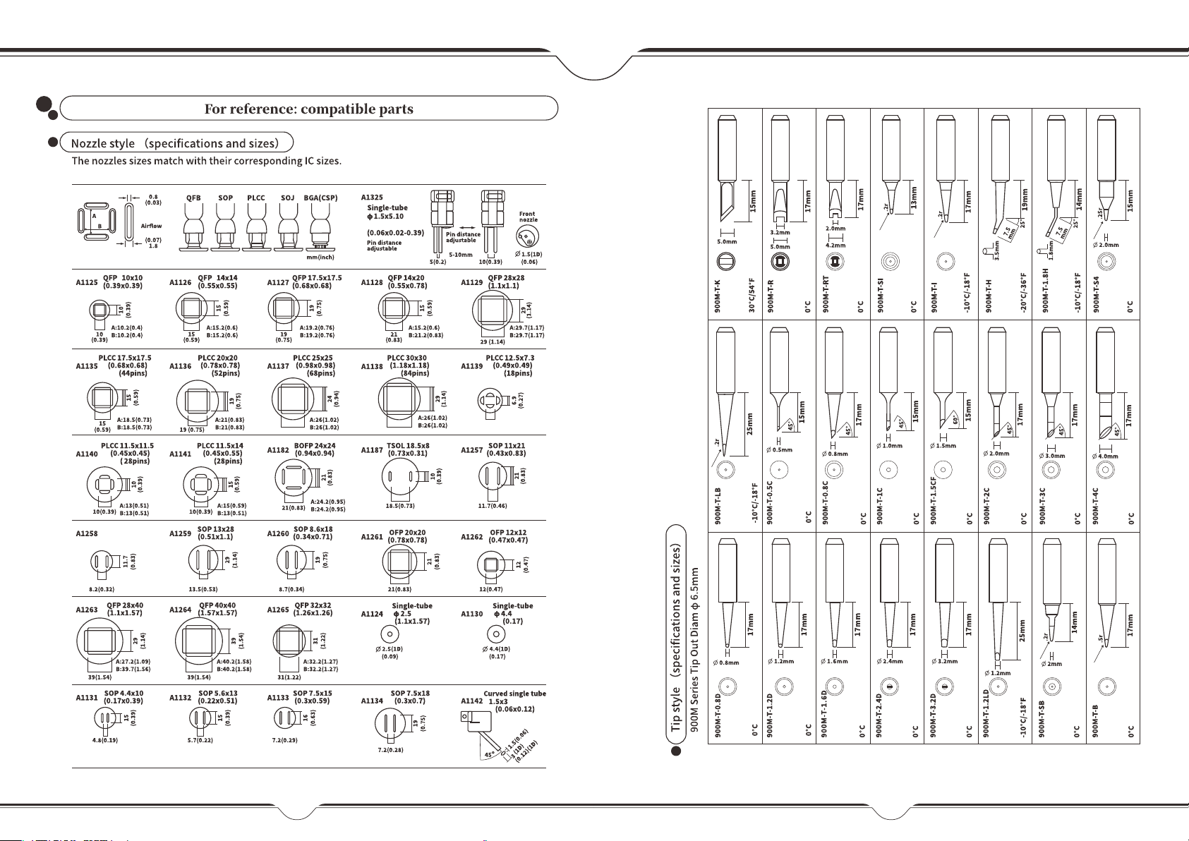
3. Select the appropriate nozzle based on your operation requirement ( temperature may vary
when using nozzles in different diameters). When using nozzles smaller than the standard ma-
chine nozzles, you MUST use the maximum air volume with a relatively lower temperature set-
ting. Complete this operation in the shortest possible duration to avoid damaging the hot air
gun.
Soldering Station
1. If a layer of oxidization forms on the surface of the soldering iron tip, a misconception can be
created that the soldering tip cannot heat up properly to melt the solder and do the tinning.
However, the actual temperatures of both the heating element and soldering tip are high. In
such an instance, please do not increase the temperature value confusedly but use a metal w-
ool ball to remove the oxidization following the steps below:
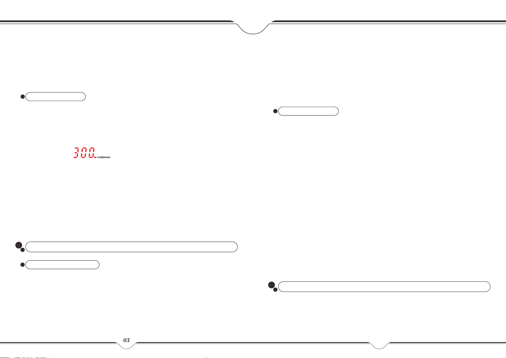
A. Set the temperature to 300°C (572°F).
B. Once the temperature has stabilized, gently rub the soldering iron tip inside the metal wool ball.
C. When the oxidization is partially removed, continue applying solder onto the tip while rubbing it until
the solder completely adheres to soldering iron tip. If the tip is too severely oxidized beyond cleaning,
replace the tip with a new one.
2. DO NOT use metal files to remove the oxidization on the soldering iron tip. If the soldering iron
tip deforms or rusts, replace it with a new tip.
3. DO NOT apply excessive force on the soldering tip when soldering. Doing so will not only dam-
age the iron tip but also not improve the heat transfer.
4. When placing the soldering iron back in its holder to idle after a high-temperature operation,
adjust the temperature to 250°C (482°F) or below for idling. Failure to do so, and leaving the s-
oldering iron tip to idle on a high-temperature setting will cause the accelerated aging of the
heating element, and shorten the lifespan of the heating element and soldering iron tip.
5. After every operation, always clean the soldering iron tip, then coat it with a layer of solder to
prevent its oxidization.
V. TROUBLESHOOTING GUIDE
1. “S-E” – This is an indication that the station’s sensor module is faulty. To resolve this issue, you
need to replace the heating element (the heating element and the sensor modules).
2. When replacing the heating element, take note of the original connecting order and colors of
the wires which MUST NOT be connected incorrectly.
0605
This manual suits for next models
1


