Magnum 3005 User manual

CONTENTS
file:///C|/Documents%20and%20Settings/Lauren/...ther%20stuff/magnum/3005%20word%20booklet.htm (1 of 12) [03/03/2003 10:16:31 PM]

CONTENTS
CONTENTS
FEATURES................................................................................................................ 1
GENERAL INFORMATION................................................................................. 2
ACCESSORIES....................................................................................................... 2
SAFETY..................................................................................................................... 2
STARTUP................................................................................................................. 3
SETTINGS................................................................................................................ 3
REMOVING QFP/SOP........................................................................................... 4
REMOVING PLCC.................................................................................................. 5
SOLDERING IRON................................................................................................. 5
ACCESSORIES....................................................................................................... 6
PCU CONFIGURATION........................................................................................ 6
STATION CONFIGURATION............................................................................... 7
PCCU CALIBRATION........................................................................................... 8
3005 STATION CALIBRATION......................................................................... 9
SPECIFICATIONS................................................................................................ 10
ABBREVIATIONS
PCB Printed Circuit Board
SMD Surface Mount Device
PCU Portable Configuration Unit
PCCU Portable Configuration and Calibration Unit
TERMINOLOGY
Reset PCU Switch unit off then on.
Reset PCCU Switch unit off then on.
Reset Station Switch unit off then on.
Configuring Transfer parameters from one device to another
Calibrating Correcting measurements against a known accurate
source
Calibrating Jigs Jigs into which the soldering iron and hot air pencil
are inserted so the temperature can be measured for calibration purposes
file:///C|/Documents%20and%20Settings/Lauren/...ther%20stuff/magnum/3005%20word%20booklet.htm (2 of 12) [03/03/2003 10:16:31 PM]

CONTENTS
FEATURES
•MICROPROCESSOR CONTROLLED 3005 STATION
•1005 85W HOT AIR PENCIL WITH AIR FLOW BUTTON
•1002/80W SOLDERING IRON WITH SOFT GRIP
•MOULDED POWER CORD
•1.5MM ROUND AND 3MM FLAT AIR NOZZLES
•FINE SOLDERING IRON TIP
•TWO CAST IRON SPRING STANDS
•SMD REMOVAL KIT
GENERAL INFORMATION
The 3005 Station is designed for SMD rework and repair
The Hot Air Pencil can be used to remove components and the
Soldering iron can be used to replace components
The user can adjust the following functions:
Temperature range of the Hot Air Pencil, Soldering iron and the
Percentage of air flow
The PCU can lock all the parameters including the energy saving mode
The PCCU automatically calibrates the Hot Air Pencil and the Soldering iron
ACCESSORIES
•PCCU Portable Configuration and Calibration Unit
Used to calibrate the Hot Air Pencil and the Soldering iron of the Station to
an accurate certified source
•PCU Portable Configuration Unit
Used as a storage device for downloading parameters from a PC onto the
3005 Station
•NOZZLES Custom made
SAFETY PRECAUTIONS
•Do not use the unit near any flammable gases, paper, liquids or dangerous materials
•Never touch the heated nozzle or allow the hot air to blow against your skin
•Never obstruct air flow as this can damage the heating element
•Take all the appropriate safety precautions when using the 3005 Station and
handpieces
•No liability is undertaken by the manufacturer for applications other than
those in the operating instructions, or for any applied modifications.
file:///C|/Documents%20and%20Settings/Lauren/...ther%20stuff/magnum/3005%20word%20booklet.htm (3 of 12) [03/03/2003 10:16:31 PM]

CONTENTS
STARTUP
•Connect power cord, Soldering iron, Hot Air Pencil and insert them into their spring
holders
•Switch on the 3005 Station.
•The °C (or °F) will appear on the LED display and the Microprocessor will do a 30
second self diagnosis test in which time any fault will be displayed as Err 1 to 4 (1=S/iron
cold, 2=S/iron overheat, 3= H/air cold, 4= H/air overheat)
•The 3005 SMD Rework Station will automatically start with the factory settings
(S/iron 350°, H/air 400°, Air flow at 60% and energy saving active).
SETTINGS
•In order to set the desired temperature for the soldering iron press the top button
(channel 1 ) the dots will start flashing
•During this period the control knob can be turned to set the new temperature
•Press the middle button (channel 2) to change the hot air temperature
•Press the lower button (channel 3) to change the air flow
•The above settings will only take effect after the dots stop flashing (+- 4 seconds)
and the display returns to actual value
•The corresponding LED will indicate which channel is being displayed
•The air flow can be intermittently activated by pressing the button on the handpiece
or continuously by switching the air pump switch on the station
•When the airflow is off (intermittent mode) the Microprocessor automatically
reduces the temperature to save energy and conserve the heating element. The temperature
will be restored when the air flow resumes.
file:///C|/Documents%20and%20Settings/Lauren/...ther%20stuff/magnum/3005%20word%20booklet.htm (4 of 12) [03/03/2003 10:16:31 PM]

CONTENTS
REMOVING QFP/SOP
Pass the stainless steel wire through and under the legs of the QFP or SOP and fix to the
PCB with adhesive tape (fig 2) Blow hot air onto the leads nearest the edge of the hand
holding the wire and carefully draw the wire outwards along the surface of the PCB so
that it sweeps between the PCB and the legs of the QFP/SOP (fig 3)
REMOVING QFP/SOP using wire hook
Insert the wire hook into the holder and place under the legs of the IC. Blow hot air onto
the legs nearest the hook when the solder melts, carefully move the hook along under the
legs. To avoid resoldering move the pencil in one direction only
file:///C|/Documents%20and%20Settings/Lauren/...ther%20stuff/magnum/3005%20word%20booklet.htm (5 of 12) [03/03/2003 10:16:31 PM]

CONTENTS
REMOVING PLCC using steel blade
Insert blade, which can be cut to any shape, into holder and fasten (fig 5)
Apply hot air continuously to both the blade and legs (fig 6)
While the solder melts insert the blade into the edge of the legs and move along. To
remove a glued component after desoldering blow hot air onto and under the component
then insert the blade under and remove
SOLDERING IRON model 1002/80w
•The Soldering iron is supplied with a high energy 80w element to enable quick
thermal transfer to the soldering tip
•A large selection of tips are available for fine pitch circuits
•Always tin soldering tip before replacing in holder
•Clean oxidation with damp sponge
SMD REMOVAL KIT
•Air nozzle 3mm flat SM100402
•Air nozzle 1.5mm round SM100401
•Stainless Steel blade SM300406
•Wire hook SM300409
•Lifting fork SM300407
•Solder braid SM300405
•Stainless steel wire SM300205
•Tweezers SM300402
•Blade holder SM300403
file:///C|/Documents%20and%20Settings/Lauren/...ther%20stuff/magnum/3005%20word%20booklet.htm (6 of 12) [03/03/2003 10:16:31 PM]

CONTENTS
ACCESSORIES
•PCU Portable configuration unit
•PCCU Portable configuration and calibration unit with
Calibrating jigs
•TIPS Full range of EW tips for the Soldering iron
PCU Configuration unit
Configuring the PCU
This procedure transfers user data from a PC to the PCU
Equipment required
Personal Computer with Windows 95 or 98, Configuration program on disc, DB-9 Serial
cable, RJ-12 to RJ-12 connector cable and PCU
Procedure
Connect the DB-9 plug to the serial port of the PC and the RJ-12 plug to the PCU
Switch on the PC, load disc and either copy configuration program to desktop or run
program from disc (slower)
Double click icon, select COM port, click ok
The parameter setting screen will appear
If all the buttons excluding the exit button are Grey then the
Communication has not been established i.e wrong COM port.
Cable not connected, unit not switched on or battery dead
Clicking on Get current values from PCCU displays all parameters previously stored on
the PCU
Clicking on Restore factory settings displays all values set at the factory
Modify values in the dialogue boxes by selecting
Range block The temperature values within which the unit will
function
Lock settings The temperature and airflow values to be locked
Checking the various functions will enable them 4
NOTE When the lock setting have been checked the values in
the Range settings will be ignored
Finally click on the Store data on PCCU and wait for the progress bar to stop moving and
the completed block to appear
Reset PCU.
file:///C|/Documents%20and%20Settings/Lauren/...ther%20stuff/magnum/3005%20word%20booklet.htm (7 of 12) [03/03/2003 10:16:31 PM]

CONTENTS
Configuring the 3005 Station
This procedure transfers data from the PCU, which has been loaded using a PC, into the 3005
Station.
The PCU can also be used to restore the station to the factory settings
Procedure
•Switch off the 3005 Station
•Insert the RJ-12 plug from PCU into the data input socket of the Station
•Switch on the PCU and then the Station which should display
“ C” with dots. The dots will disappear within two seconds.
•Press the Function button on the PCU until the configure LED is lit (Or restore factory
settings LED if required)
•Press the Execute button
•The Busy LED will turn on for a second and “Con” will be displayed on the Station.
•When the Busy LED turns off, unplug the PCU and Reset the Station.
•The new parameters have now been downloaded
file:///C|/Documents%20and%20Settings/Lauren/...ther%20stuff/magnum/3005%20word%20booklet.htm (8 of 12) [03/03/2003 10:16:31 PM]

CONTENTS
PCCU configuration and calibration unit
Configuration Procedure
•This procedure is the same as the PCU above.
Calibration Procedure
•This allows for the calibration of the Soldering iron and the Hot air pencil to a
known calibrated source (Type K thermocouple simulator)
Calibrating the PCCU
•If required this procedure can be done by the factory.
Equipment required (This section can be omitted if PCCU is pre-calibrated)
•PCCU unit ,Type K thermocouple simulator with input cable
•PC with calibration program loaded from the disc supplied
•Female DB-9 serial cable, RJ-12 to RJ-12 connector.
Procedure
•Connect the PCCU to the PC using the serial cable
•Connect the thermocouple simulator to the Soldering iron input of the PCCU.
•Load the Calibration program on the PC, select the correct Com port and reset the
PCCU.
•The screen on the PC will start with a instruction to connect the simulator to the
soldering iron input (if this does not happen try another Com port, check serial cable and
PCCU)
•Follow the instructions on the PC and only click the OK button when the
simulator’s temperature has been set to the requested temperature and instructions
to change inputs have been carried out.
•If, at any time the procedure is interrupted, the Calibration will be invalid and has
to be restarted.
IT IS VERY IMPORTANT THE ABOVE PROCEDURE IS CARRIED OUT
CORRECTLY.
Calibrating the 3005 Station
This procedure automatically calibrates the 3005 Station’s Soldering iron and Hot air
pencil to the PCCU, which has been precalibrated to a certified source.
file:///C|/Documents%20and%20Settings/Lauren/...ther%20stuff/magnum/3005%20word%20booklet.htm (9 of 12) [03/03/2003 10:16:31 PM]

CONTENTS
Equipment required
•A calibrated PCCU
•The 3005 station with the Soldering iron and Hot air pencil
•The Soldering iron and Hot air pencil calibration jigs
•The RJ-12 to RJ-12 connecting cable
Note: The calibration procedure must be carried out in a closed environment, as the
slightest breeze will affect the accuracy.
Procedure
•Connect the PCCU with the RJ-12 cable to the 3005 Station.
•Connect the thermocouple plugs to the correct inputs
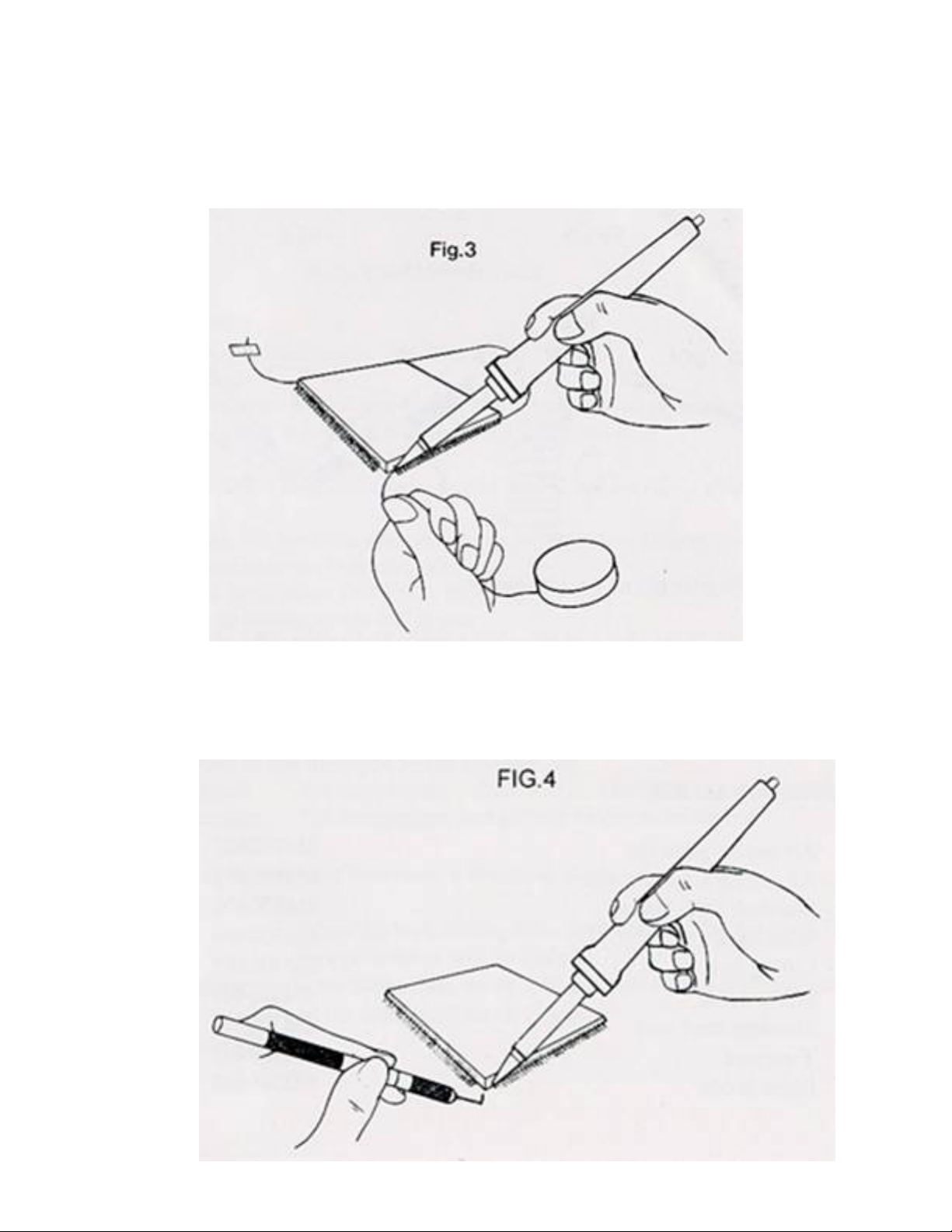
•Connect the Soldering iron and Hot air pencil to the Station and insert into their
respective jig’s.
•Switch on the PCCU
•Switch on the 3005 Station
•The dots will disappear within two seconds but the C or F will remain.
•If this does not happen the connection or the cable is faulty.
•Press the Function button on the PCCU until the calibrate LED is lit.
•Press the Execute button on the PCCU.
•If all the LED’s on the PCCU light up, then there is a fault and the PCCU has to
be recalibrated.
•If everything is ok then the Busy LED will light and the calibration procedure will
start.
•Calibration consists of six phases: Warming up, and calibrating of the following
temperature points, 100 °C, 200 °C, 300 °C, 400 °C and 500 °C.
•The duration of the procedure is determined by the factory
(± 20 minutes)
•During calibration the display on the Station cycles through three values :
•The setpoint temperature (shown when the dots are flashing)
•The temperature of the Soldering iron measured by the PCCU (shown when the
Soldering iron LED is on)
•The temperature of the Hot air pencil measured by the PCCU (shown when the Hot
air pencil LED is on)
•The procedure will stop if the temperature measured by the PCCU is out of
specification.
•If the Calibrate, Configure, Busy and Complete LED light up, then the Soldering
iron is out of specification.
•If the Calibrate, Reset to factory setting, Busy and Complete LED light up then
the Hot air pencil is out of specification.
file:///C|/Documents%20and%20Settings/Lauren...her%20stuff/magnum/3005%20word%20booklet.htm (10 of 12) [03/03/2003 10:16:31 PM]

CONTENTS
•
Causes of failure
•The calibration jig, heating element, sensor, or wiring may be faulty.
•Check that the Soldering iron and Hot air pencil are properly inserted in their jig’s
•When the calibration is complete the Complete LED on the PCCU will light and the
Station will display CAL
•Disconnect the Station and jig’s from the PCCU.
•Reset the 3005 Station for new values to take effect.
SPECIFICATIONS
Mains input voltage: 220V – 240V 50/60Hz
Power consumption: 0.6 Amps fuse 1A f/b
Output power: 24V 85W + 24V85W
Air flow: 1.5 to 6.5 litres/min
Temperature: Soldering iron 100° to 450° ± 4 °C
Hot air pencil 180° to 480° ±10 °C
Dimensions: L 250mm W 250mm H 105
Weight: 4 KGS (8.8LBS)
file:///C|/Documents%20and%20Settings/Lauren...her%20stuff/magnum/3005%20word%20booklet.htm (11 of 12) [03/03/2003 10:16:31 PM]

CONTENTS
Manufactured and Designed by Lauren Manufacturing Co.
Software designed by Spline Technologies.
file:///C|/Documents%20and%20Settings/Lauren...her%20stuff/magnum/3005%20word%20booklet.htm (12 of 12) [03/03/2003 10:16:31 PM]
Table of contents