Element E3 F Series User manual
Installation Instructions for 920E3 - -HMH AIC FL
Round or Square Type Adjustable HousingIC
with Toroidal Transformer for Flanged Trims
E3_F_- _HAIM 1.5
HALOGEN MR ROUND SQUARE FLANGED16 - /
GP I :ENERAL RODUCT NFORMATION
This product can be dimmed with a low-voltage magnetic
dimmer.
For insulation applications above R25, no branch circuits
allowed.
This instruction shows a typical installation.
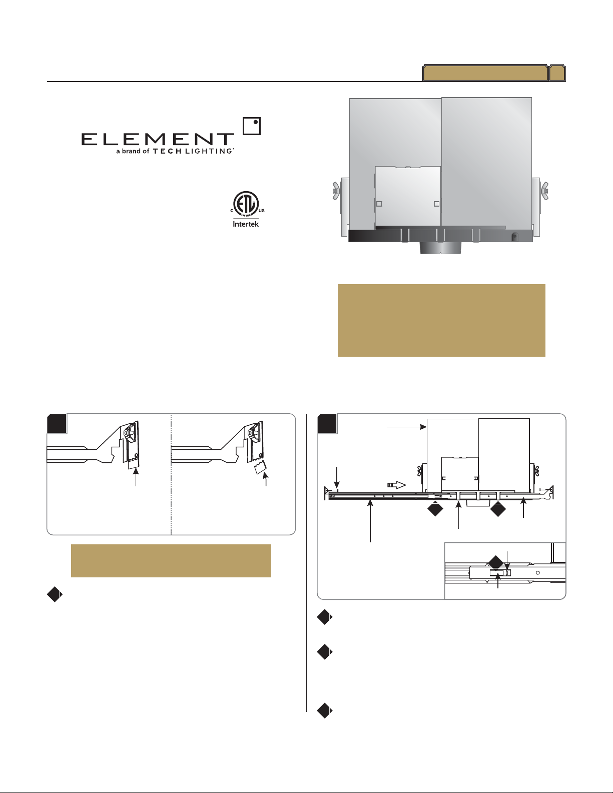
1
HOUSING CLASP
HOUSING
1B
INNER ADJUSTABLE BAR
OUTER ADJUSTABLE BAR
TAB
STOP POINT
3
3
NAIL
2
Slide the inner adjustable bar completely through the
three housing clasps. Make sure the nail is on top.
Slide and push the outer adjustable bar completely onto
the inner adjustable bar so that the tab clicks into place
behind the stop point.This will prevent the adjustable bars
from coming apart.
Repeat steps 2 & 3 for the other side of the housing.
2
3
4
Install the Housing with Adjustable Bars
1A
BREAK OFF
AND DISCARD
¾” or thicker
½” to ¾”
LEAVE TAB
IN PLACE
Keep Tab for ceiling ½” to ¾” thick.
When using adjustable hanger bars with ½”to ¾” thick
ceilings, leave the tab of the hanger bars in place.
Break off Tab for ceiling ¾” or thicker.
When using adjustable hanger bars with ¾”or thicker
ceilings, remove the tab by bending it at the perforation.
1
NOTE: Skip this section if installing the housing
with butterfly brackets.
CAUTION RISK OF FIRE-
This product must be installed in accordance with
the applicable installation code by a person familiar
with the construction and operation of the product
and the hazards involved.
Use minimum 90°c supply conductors.
2
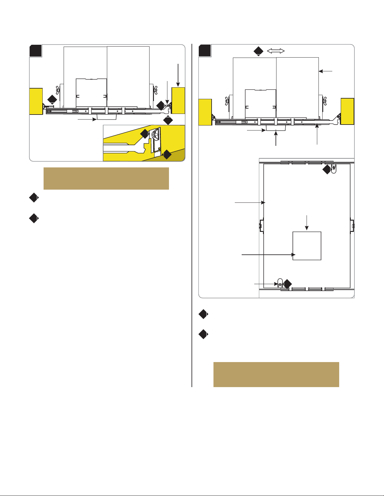
#6 SELF TAPPING SCREW
NOTCH
8
TRIM HOLDER
HOUSING
Adjust the trim holder position (horizontal position) by
sliding the housing on adjustable bars.
When the desired location is achieved, tighten the two #6
self tapping screws to lock the housing onto the adjustable
bars.
7
8
NOTE: Notches in trim holder can be used to
align multiple housings using a laser or string.
8
1C
TRIM HOLDER
NAIL
JOIST
6
6
5
NOTE: The adjustable bars can be mounted to
joists that are spaced 16" - 24" apart.
Align the bottom of the end plates with the bottom of the
ceiling joists.
Level the adjustable bars and, with a hammer, tap the nails
completely into the joists to secure the adjustable bars in
place.
5
6
5
6
1D
ADJUSTABLE BAR
7
TRIM HOLDER
NOTCH
HOUSING
3
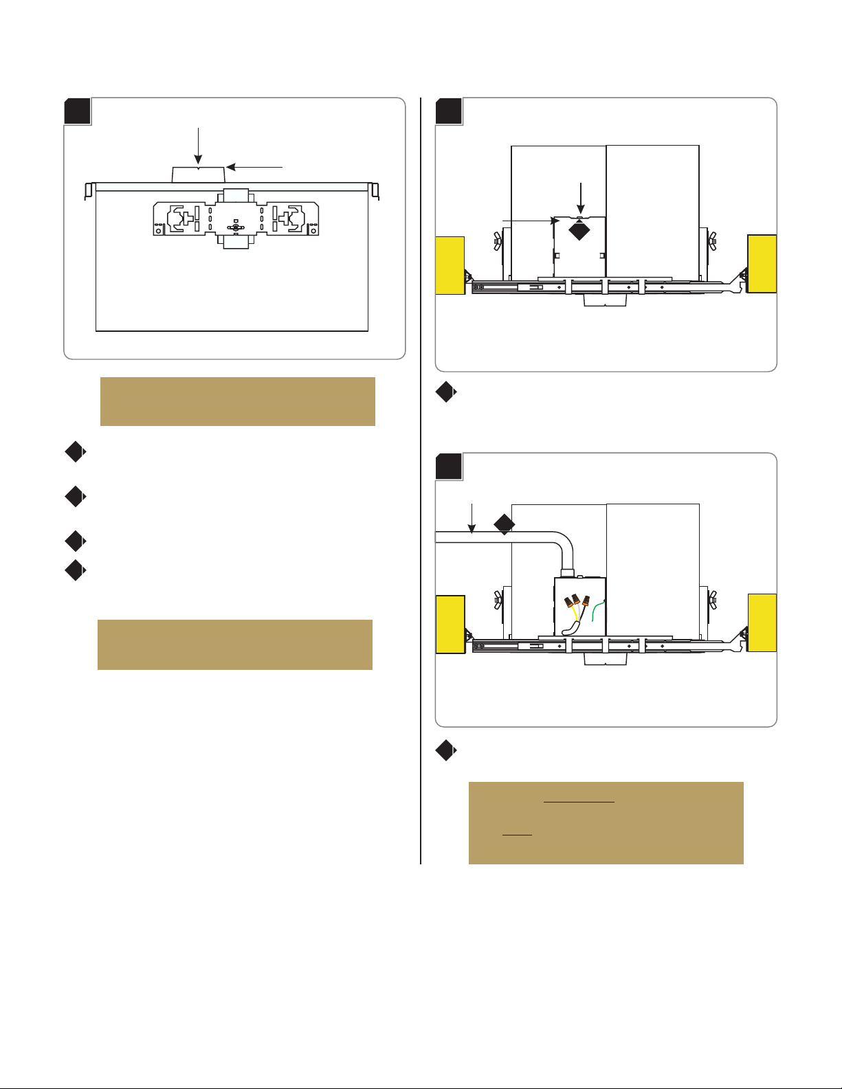
ELECTRICAL
BOX COVER 1
TAB
Connect Power to the Housing
3A
Push the tab on the housing electrical box up and remove
the electrical box cover.
1
BUTTERFLY
BRACKET
TRIM HOLDER
WING NUT
1
2
NOTE: Notches in trim holder can be used to
align multiple housings using a laser or string.
NOTCH
Install the Housing with Butterfly
Brackets
2A
Slightly loosen the wing nut to slide the butterfly bracket
up or down.
After achieving the proper location, tighten the wing nut
to secure the butterfly bracket in place.
Repeat steps 1 and 2 on for the other butterfly bracket.
Utilize the butterfly brackets to install the housing in
accordance with local electrical codes.
1
2
3
4
NOTE: Notches in trim holder can be used to
align multiple housings using a laser or string.
NOTE: Skip this section if installing the housing
with adjustable bars.
3B
Install the conduit to the housing electrical box.
2
WARNING: RISK OF FIRE: When using the
housing electrical box for power feed through,
use 4 - #12 , or 6 - #14 branch
MAX AWG AWG
circuit wires.
CONDUIT
2

4
Install Drywall or Suspended Ceiling
3C
Run the power line wires into the housing electrical box.
Connect the neutral power line wire to the white
transformer wire with a wire nut.
If using a dimmer, connect the hot power line wire to the
yellow transformer wire with a wire nut. Make sure that
the black transformer wire is disconnected, capped with
a wire nut.
If using a switch, connect the hot power line wire to the
black transformer wire with a wire nut. Make sure that the
yellow transformer wire is disconnected, capped with a
wire nut.
Make sure that housing is grounded in accordance with
local electrical codes.
Replace the electrical box cover. Make sure that the top
edge of the cover snaps under the tab.
3
4
5a
5b
5b
5a
5a
5b
6
4
4
6
6
7
4A
For round trims, mark a 3-7/8" diameter circle on drywall.
Cut out the marked section.
For square trims, mark a 3-7/8" square on drywall. Cut out
the marked section.
1
3-7/8" 3-7/8"
ROUND TRIM HOLDER SQUARE TRIM HOLDER
Align the cut out section of drywall with the trim holder
and install the drywall.
2
2
DRYWALL TRIM HOLDER JOIST
4B
5
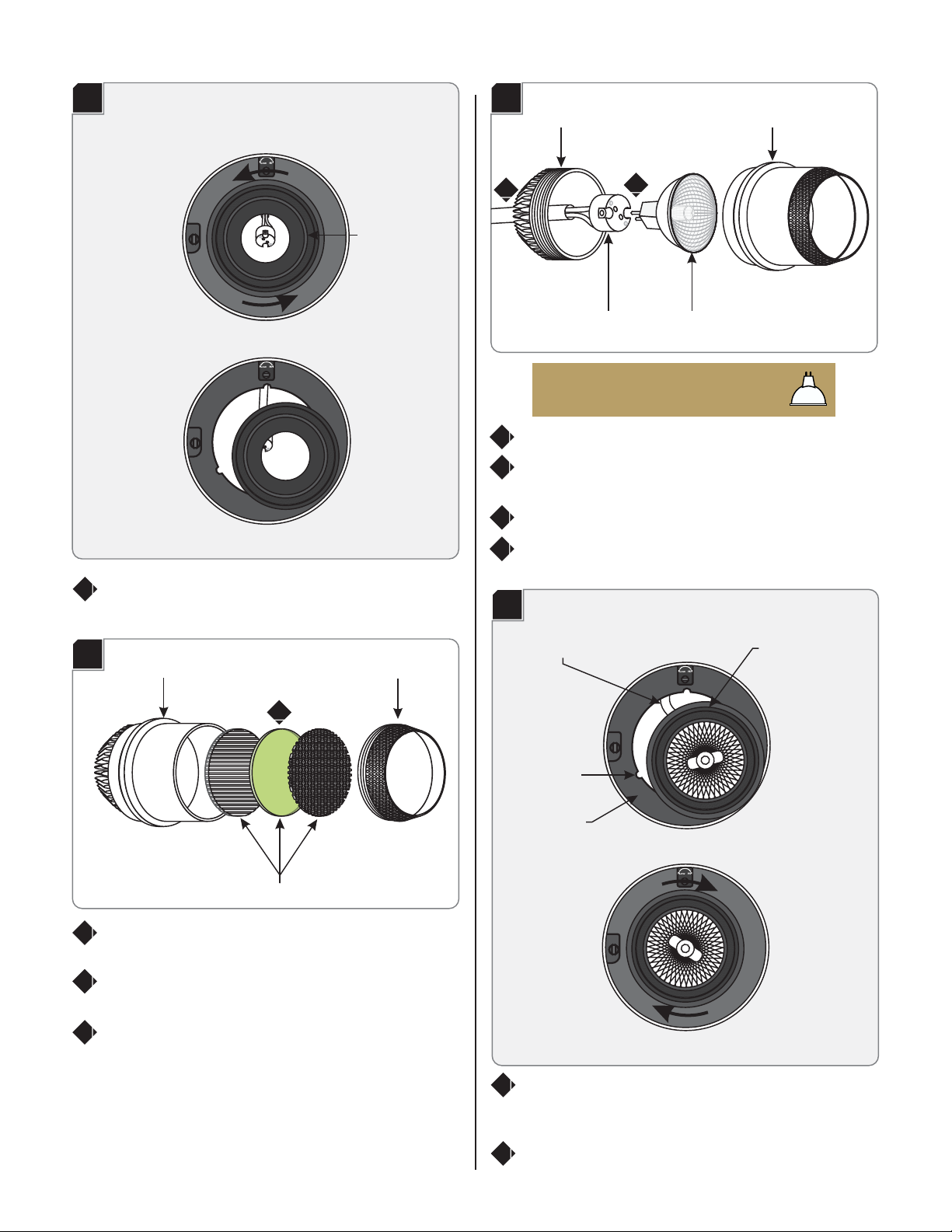
Install the Lamp & Lens Accessories
To install a lens accessory (optional), unscrew the snoot
from the lamp cartridge.
Place a maximum of three accessories into the lamp
cartridge.
Replace and tighten the snoot completely to the lamp
cartridge.
2
1To release the lamp cartridge, rotate it counter clockwise
and gently pull out the assembly.
5B
LAMP CARTRIDGE SNOOT
LENS ACCESSORIES
3
4
3
Unscrew the lamp cartridge base from the lamp cartridge.
Pull out the socket from the lamp housing and feed it
through the lamp base.
Push the lamp pins completely into the socket holes.
Place the lamp into the lamp cartridge and reinstall the
lamp cartridge base and firmly tighten.
5
Use Watt Type 16 HalogenMAX 50 MR
Lamp.
6
LAMP
SOCKET
5C
LAMP CARTRIDGE
LAMP CARTRIDGE BASE
9Feed the socket wire sleeve back into the lamp housing
and align the lamp assembly with the keyed slots on the
lamp housing.
Place the lamp assembly into the lamp housing and rotate
it until it locks into place.
10
7
8
67
5A
Low Hi
LAMP CARTRIDGE
Low Hi
Low Hi
5D
Low Hi
KEYED SLOT
LAMP CARTRIDGE
SOCKET WIRE SLEEVE
LAMP HOUSING

6
Adjust the Lamp Housing
2To tilt the lamp housing vertically, rotate the tilt adjustment
screw until the desired angle is reached.
NOTE: Lamp housing can tilt 40° vertically. Lines
on lamp housing are 5° apart.
NOTE: Lamp housing can rotate 361° horizontally.
3Pull the rotation lock down to unlock the lamp housing.
Rotate the lamp housing horizontally. When the desired
position is achieved push the rotation lock up to lock the
lamp housing in place.
4
Low Hi
6A
NOTE: The location of the height adjustment
screw is indicated with the words Low and Hi.
HEIGHT ADJUSTMENT SCREW
1
6B
20
40
30
10
0
INDICATOR
1
2
TILT ADJUSTMENT SCREW
Low Hi
2
6C ROTATION LOCK
LowH
i
1To adjust the height rotate the height adjustment screw.
Adjust upward to minimize glare and flash on the trim or
downward for maximum light output and efficiency.

7

8
7400 Linder Ave, Skokie, 60077IL
847.410.4400
www.element-lighting.com
© 2016 Element Lighting, L.L.C. All rights reserved.The "Element" graphic
is a registered trademark of Element. Element reserves the right to
change specifications for product improvements without notification.
A Generation Brands Company
SAVE THESE INSTRUCTIONS!
Popular TV Mount manuals by other brands

Multibrackets
Multibrackets M Flexarm Pro Extenderkit 600x900 installation manual

Desalto
Desalto Sail 304 Assembly instruction

Catalyst
Catalyst 63607151 Instruction booklet

FONESTAR
FONESTAR STT-7144CN instruction manual

Mounting Dream
Mounting Dream MD2268-MK Installation instruction

QualGear
QualGear QG-DM-01-022 installation manual


Leviton
Leviton ACENTI ACW14 installation instructions

Sony
Sony SU-WL500 Instructions (SU-WL500 Wall-Mount... installation manual

AVF
AVF JZL6701 manual

peerless-AV
peerless-AV DS509 Installation and assembly

Sanus Systems
Sanus Systems SSMK1 manual

Commercial Electric
Commercial Electric MB-52472 Use and care guide